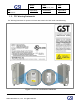
Version Date 1.3 Title November 18, 2016 Prepared by Reviewed by Page 1/ 61 Approved by USER MANUAL GST-IC-ELITE-1943 USER MANUAL November 18, 2016 GS Instech Co., Ltd. 1 ©2016 GS Instech Co., Ltd. All rights reserved.
Version Date 1.3 Title November 18, 2016 Prepared by Reviewed by Page 2/ 61 Approved by USER MANUAL [CHANGE RECORD] DATE NAMES DESCRIPTIONS VERSION September 5, 2016 H.J.CHOI Original Draft 1.0 September 23th, 2016 H.J.CHOI Add a Modem redundant Configuration 1.1 November 11, 2016 H.J.CHOI Change a Model Number 1.2 Edit contents November 18, 2016 H.J.CHOI Edit according to FCC/ UL Regulation 2 ©2016 GS Instech Co., Ltd. All rights reserved. 1.
Version Date 1.3 Title November 18, 2016 Prepared by Reviewed by Page 3/ 61 Approved by USER MANUAL [TABLE OF CONTENTS] CHAPTER’s INDEX 1. GENERAL ............................................................................ 8 1.1. Purpose ............................................................................................ 8 1.2. Copyright .......................................................................................... 8 1.3. FCC Warning Statements ..........................
Version Date 1.3 Title November 18, 2016 Prepared by Reviewed by Page 4/ 61 Approved by USER MANUAL 4.4. Configuration & Mechanical Specification ................................................ 20 5. SYSTEM BLOCK CONFIGURATION.............................................. 21 5.1. Block Diagram ................................................................................... 21 5.2. Signal & Data Flow ............................................................................ 22 6.
Version Date 1.3 Title November 18, 2016 Prepared by Reviewed by Page 5/ 61 Approved by USER MANUAL 8.3. Main Screen ..................................................................................... 34 8.4. RF Status ......................................................................................... 35 8.5. RF Configuration ............................................................................... 36 8.6. Alarm Configuration .....................................................
Version Date 1.3 Title November 18, 2016 Prepared by Reviewed by Page 6/ 61 Approved by USER MANUAL 9.4.3. 9.5. Recommended Distance for installing system mounting ................................................................................................ 58 Cable Connection .............................................................................. 59 9.5.1. AC Power cable connection ........................................................................................................
Version Date 1.3 Title November 18, 2016 Prepared by Reviewed by Page 7/ 61 Approved by USER MANUAL TABLE’s INDEX TABLE 1. GST-IC-ELITE-1943 UNIT CONFIGURATION .................................................................................................................................... 15 TABLE 2. GST-IC-ELITE-1943 EXTERNAL INTERFACE DESCRIPTION ........................................................................................................ 16 TABLE 3.
Version Date 1.3 Title November 18, 2016 Prepared by Reviewed by Page 8/ 61 Approved by USER MANUAL 1. General 1.1. Purpose This document introduces features, specifications, structures and operation guideline for the GST-IC-ELITE-1943 CDMA & LTE Repeater 1.2. Copyright All text and image in this document are subject to the copyright of GS Instech Co., Ltd. This document may not be reproduced, distributed, or modified without the written permission of GS Instech Co., Ltd. 8 ©2016 GS Instech Co.
Version Date 1.3 Title November 18, 2016 Prepared by Reviewed by Page 9/ 61 Approved by USER MANUAL 1.3. FCC Warning Statements FCC Warning Statement for system is follows. Must attach the label under manufacturing. Figure 1. FCC/ UL Certification Statement 9 ©2016 GS Instech Co., Ltd. All rights reserved.
Version Date 1.3 Title November 18, 2016 Prepared by Reviewed by Page 10/ 61 Approved by USER MANUAL FCC Part 15.105 statement (Class A) This equipment has been tested and found to comply with the limits for a Class A digital device, pursuant to part 15 of the FCC Rules. These limits are designed to provide reasonable protection against harmful interference when the equipment is operated in a commercial environment.
Version Date 1.3 Title November 18, 2016 Prepared by Reviewed by Page 11/ 61 Approved by USER MANUAL 2. Introduction 2.1. System Overview GST-IC-ELITE-1943 is designed to improve coverage and capacity of CDMA Band Class 1 and LTE Band25 services in all shadowed and blanked areas of Sprint network. GST-IC-ELITE-1943 receives and improves weak signals as cancelling the multi-path interference even if there is a lack of isolation between Donor and Service antenna.
Version Date 1.3 Title November 18, 2016 Prepared by Reviewed by Page 12/ 61 Approved by USER MANUAL 2.2.
Version Date 1.3 Title Page November 18, 2016 Prepared by Reviewed by USER MANUAL 3. System Design 3.1. Perspective View Locking Bolt Handle for carrying FAN Connector FAN Installation Bracket FAN Cable Figure 3. GST-IC-ELITE-1943 Perspective View 13 ©2016 GS Instech Co., Ltd. All rights reserved.
Version Date 1.3 Title Page November 18, 2016 Prepared by Reviewed by 14/ 61 Approved by USER MANUAL 3.2. Exterior View [Top View] 13.2"(335mm) 19" (480mm) 7.8"(200mm) [Left View] [Front View] [Right View] [Bottom View] Figure 4. GST-IC-ELITE-1943 Exterior View 14 ©2016 GS Instech Co., Ltd. All rights reserved.
Version Date 1.3 Title Page November 18, 2016 Prepared by 15/ 61 Reviewed by Approved by USER MANUAL 3.3. Interior View 4 1 6 2 5 3 8 7 9 Figure 5. GST-IC-ELITE-1943 Interior View No Name 1 Power Supply Unit 2 SNMP Board 3 Surge Protect Board RET Surge Protection 4 High Power Amplifier For generating High RF Power 5 ICM (Interference Cancellation Module) Remark Input: 110Vac~240Vac/ Output (DC):+32V, 24V, 5.
Version Date 1.3 Title Page November 18, 2016 Prepared by 16/ 61 Reviewed by Approved by USER MANUAL 3.4. External Interface 2 AC IN 1 4 3 RET FAN 7 8 DONOR ANT 6 5 SERVICE ANT Figure 6. GST-IC-ELITE-1943 External Interface No NAMES DESCRIPTION SPECIFICATION 1 AC IN AC Power Input Port MS-3102A-10SL-3P 2 RJ-45 & SIM CARD SLOT Local Maintenance & Modem Activation Local: RJ-45 SLOT: AUSIM-115AADA0-R02 3 RET Remote Antenna Control Port (AISG 2.0) SU20SPR-8S/ 29V_1.
Version Date 1.3 Title Page November 18, 2016 Prepared by Reviewed by 17/ 61 Approved by USER MANUAL 4. System Specification 4.1. RF Performance Parameter Down Link Up Link Frequency Range 1930MHz ~ 1995MHz 1850MHz ~ 1915MHz Input Range -62dBm ~ -32dBm/ Total -75dBm ~ -45dBm/ Total Output Power Channel Capacity Gain +43dBm (20W) max. Remark +30dBm (1W) max. CDMA 10W+LTE 10W / Total 【CDMA】 15MHz max/ 1.25MHz Step 【LTE】 10MHz max (9.
Version Date 1.3 Title Page November 18, 2016 Prepared by Reviewed by 18/ 61 Approved by USER MANUAL Parameter Down Link Up Link Frequency Error < 0.05ppm Downlink Transmitter Intermodulation > 153dBc Suppress Uplink Intermodulation Product Uplink Transmitter Intermodulation > 153dBc Suppress Downlink Intermodulation Product System Delay < 4us Noise Figure Less than 4dB @ Min & Max Gain TX/RX Isolation > 110dBc Cancellation Depth G=I+15dB VSWR < 1.5 : 1 Remark CDMA & LTE <-5.
Version Date 1.3 Title Page November 18, 2016 Prepared by Reviewed by 19/ 61 Approved by USER MANUAL 4.2. ICS General Performance No. Parameter Condition Specification 1 Gain Re-Tracking Time after reset Target Gain ±1dB < 10 Sec 2 Isolation Sensing Range -10dB < Gain < 10dB Accuracy ±1 -20dB < Gain < 20dB Accuracy ±3 3 G = I + 15dB Static General Operating 4 G = I 10Hz Fast Fading Table 4. GST-IC-ELITE-1943 ICS General Performance 4.3. Frequency Information 4.3.1.
Version Date 1.3 Title November 18, 2016 Prepared by Reviewed by Page 20/ 61 Approved by USER MANUAL 4.4. Configuration & Mechanical Specification Parameter Donor/ Service Antenna Filter Power Supply Specification One Output port-duplex type for LTE & CDMA AC Input Voltage: 110~240V (50/60Hz) Remark Donor Duplexer include Modem ANT port 3.7A max DC Output Voltage: 32V/ 24V/ 5.
Version Date 1.3 Title November 18, 2016 Prepared by Reviewed by Page 21/ 61 Approved by USER MANUAL 5. System Block Configuration 5.1. Block Diagram Figure 7. GST-IC-ELITE-1943 Block Diagram Configuration The repeater improves service in the Sprint Network of CDMA Class 1 & LTE Band 25. User may select frequency band according to the site peculiarities.
Version Date 1.3 Title Page November 18, 2016 Prepared by Reviewed by 22/ 61 Approved by USER MANUAL 5.2. Signal & Data Flow 9 AMP Control 3 ICM Control 7 4 8 2 PSU signal LTE Modem +32Vdc +5.6Vdc +5.6Vdc CDMA Modem LTE Modem +32Vdc CDMA Modem +24Vdc 10 1 5 6 Supply DC for FAN (+24V) RET Control Insert AC Figure 8.
Version Date 1.3 Title November 18, 2016 Prepared by Reviewed by Page 23/ 61 Approved by USER MANUAL 6. Function Description 6.1. General • Ability to perform a function about management & operation (Band independently) - Gain & Level Adjustment - Smart AGS, ASD, ALC, Gain Balance, Channel Selection • ILC operation based on ICS function • Ability to initialize the entire system (include with local & remote control) 6.2.
Version Date 1.3 Title November 18, 2016 Prepared by Reviewed by Page 24/ 61 Approved by USER MANUAL 6.3. ALC/ AGC & Gain Balance Function ALC means a function which controls gain automatically in order to protect H/W in case of excessive out power more than user-defined threshold value upon Input RSSI change, and to keep signal quality. AGC means UL Gain Balancing function based on DL Gain. 6.4.
Version Date 1.3 Title Page November 18, 2016 Prepared by Reviewed by 25/ 61 Approved by USER MANUAL 6.5.
Version Date 1.3 Title November 18, 2016 Prepared by Reviewed by Page 26/ 61 Approved by USER MANUAL 6.6. ICS Function • Provide an Ability to operate stable under lack of isolation between Donor antenna and Service antenna - In case of operating under Repeater Gain=105dB, Antenna Isolation=90dB ICS function ON Figure 12.
Version Date 1.3 Title November 18, 2016 Prepared by Reviewed by Page 27/ 61 Approved by USER MANUAL 6.7. Download • To changed and updated features of system operation and monitoring program - Upgrade software or install a patch with minimal loss of service (Less than 2mins except for FPGA Program) - To handle a full software load and to receive/ error-check at the same time - If the load is rendered unsatisfactory after the upload, it will automatically revert to the old software load 6.8.
Version Date 1.3 Title Page November 18, 2016 Prepared by Reviewed by 28/ 61 Approved by USER MANUAL 7. Status/ Control & Alarm Monitoring 7.1. Status Monitoring and Control Parameters • In case of control parameter, present status but also setting value display on Web-UI.
Version Date 1.3 Title Page November 18, 2016 Prepared by Reviewed by 29/ 61 Approved by USER MANUAL Parameter Status ASD Common Control Description ○ Set the Auto Shutdown function On/Off ICM Version ○ Display a ICM Software Version DL/UL FPGA Version ○ Display a DL/UL FPGA Software Version Final AMP Version ○ Display a Final AMP Software Version Site ID ○ Write the location Info.
Version Date 1.3 Title November 18, 2016 Prepared by Reviewed by Page 30/ 61 Approved by USER MANUAL 7.2.
Version Date 1.
Version Date 1.3 Title Page November 18, 2016 Prepared by Reviewed by 32/ 61 Approved by USER MANUAL 8. Web-UI Overview • Provide all functions that can be performed at the local craft port will be available thru the remote interface • Support the GUI pages that will be addressable via the LTE/ CDMA wireless modem • Support Remote access that will enable troubleshooting down to a specific location 8.1.
Version Date 1.3 Title November 18, 2016 Prepared by Reviewed by Page 33/ 61 Approved by USER MANUAL 8.2. Login-In Screen • Web-UI Screen for Log-In • After Logging, User can be able to operate Web-UI • Register & Delete a User name/ Password: Refer to 9.8 User Management • Display Total Alarm & Shutdown Status • Enter the IP Address "192.168.1.1" into your browser address bar and you will be redirected to the Login page 33 ©2016 GS Instech Co., Ltd. All rights reserved.
Version Date 1.3 Title November 18, 2016 Prepared by Reviewed by USER MANUAL 8.3. Main Screen • Web-UI Screen for Main Menu • Able to select function RF Configuration & Status monitoring 34 ©2016 GS Instech Co., Ltd. All rights reserved.
Version Date 1.3 Title November 18, 2016 Prepared by Reviewed by USER MANUAL 8.4. RF Status • Web-UI Screen for display Repeater’s RF Status 35 ©2016 GS Instech Co., Ltd. All rights reserved.
Version Date 1.3 Title November 18, 2016 Prepared by Reviewed by Page 36/ 61 Approved by USER MANUAL 8.5. RF Configuration • Web-UI Screen in order to change the RF values • User may change the various RF values of the repeater on this page • Changes will not take effect until you click "Apply" button • This menu is where the installer will choose references for specific implementation 36 ©2016 GS Instech Co., Ltd. All rights reserved.
Version Date 1.3 Title November 18, 2016 Prepared by Reviewed by Page 37/ 61 Approved by USER MANUAL 8.6. Alarm Configuration • Web-UI Screen for Alarm Configurations • Define a TRAP alarm thru SNMP Mapping • Decide to activate an each alarm • When "Report Alarm" is OFF, all alarms are disabled. When "Report Alarm" is ON, alarms can be Enable/ disabled individually 37 ©2016 GS Instech Co., Ltd. All rights reserved.
Version Date 1.3 Title November 18, 2016 Prepared by Reviewed by Page 38/ 61 Approved by USER MANUAL 8.7. Fake Alarm Configuration • Web-UI Screen for Fake Alarm Configurations • In order to test about transmitting alarm to Sprint Server, Fake alarm occur in SNMP Board 38 ©2016 GS Instech Co., Ltd. All rights reserved.
Version Date 1.3 Title November 18, 2016 Prepared by Reviewed by Page 39/ 61 Approved by USER MANUAL 8.8. Communication Configuration • Web-UI Screen for Communication Configurations • Set the information in order to connect to Sprint Server • On this page you can change the various values related to IP network. Because the Web-UI is based on the IP network, incorrect configuration may make it impossible to connect to the Web-UI.
Version Date 1.3 Title November 18, 2016 Prepared by Reviewed by Page 40/ 61 Approved by USER MANUAL 8.9.
Version Date 1.3 Title November 18, 2016 Prepared by Reviewed by Page 41/ 61 Approved by USER MANUAL 8.10. Alarm Log • Web-UI Screen for finding Alarm log • You can see the history of reported and reset Alarms.
Version Date 1.3 Title November 18, 2016 Prepared by Reviewed by USER MANUAL 8.11. Log • Web-UI Screen for reading a List of operation history • Logs will maintain a history of up to 30 cycles 42 ©2016 GS Instech Co., Ltd. All rights reserved.
Version Date 1.3 Title November 18, 2016 Prepared by Reviewed by Page 43/ 61 Approved by USER MANUAL 8.12. • Troubleshooting Web-UI Screen for informing a contact information in case of occurring Field Troubleshooting 43 ©2016 GS Instech Co., Ltd. All rights reserved.
Version Date 1.3 Title November 18, 2016 Prepared by Reviewed by Page 44/ 61 Approved by USER MANUAL 8.13. Software Update • Web-UI Screen for downloading a software • Procedure 1. Go to "Remote Software Upgrade" link 2. Click Browse button to select the upgrade file from the laptop 3. Choose the file to upgrade. Provided by manufacturer. After you choose the file, You should click "upload" to send the file from your laptop to the Repeater 4.
Version Date 1.3 Title November 18, 2016 Prepared by Reviewed by Page 45/ 61 Approved by USER MANUAL 8.14. System Reset • Web-UI Screen for resetting the system • Click on the desired reset action • Clink "Yes" to reset the repeater via a soft-boot. This will not change any of the current settings 45 ©2016 GS Instech Co., Ltd. All rights reserved.
Version Date 1.3 Title November 18, 2016 Prepared by Reviewed by USER MANUAL 8.15. • Factory Default Setting Web-UI Screen for Default Setting before operating 46 ©2016 GS Instech Co., Ltd. All rights reserved.
Version Date 1.3 Title November 18, 2016 Prepared by Reviewed by Page 47/ 61 Approved by USER MANUAL 8.16. • Configuration Transfer Web-UI Screen for mutual information transfer between Repeater and Local Craft 47 ©2016 GS Instech Co., Ltd. All rights reserved.
Version Date 1.3 Title November 18, 2016 Prepared by Reviewed by Page 48/ 61 Approved by USER MANUAL 9.
Version Date 1.3 Title November 18, 2016 Prepared by Reviewed by Page 49/ 61 Approved by USER MANUAL 9.1. Warnings and Hazards 9.1.1. Electric Shock • Opening the Repeater could result in electrical shock and may cause severe injury • Operating the Repeater with antennas in very close proximity facing each other could lead to severe damage to the repeater 9.1.2.
Version Date 1.3 Title Page November 18, 2016 Prepared by 50/ 61 Reviewed by Approved by USER MANUAL 9.3. Cabling The cabling diagram of the GST-IC-ELITE1943 is as follows From GST-IC-ELITE1943 To Cable MGB Frame Ground Cable: AWG 6/ 10ft Circuit Breaker Box AC Power Cable: AWG 16/ 6ft RF Antenna Feeder Cable: 1/2 inch Feeder Line RF Antennas RET control Cable (option) No use for the unauthorized device When installing the system, must check the devices that use is authorized.
Version Date 1.3 Title November 18, 2016 Prepared by Reviewed by Page 51/ 61 Approved by USER MANUAL 9.4. Service Man Installation Guide 9.4.1. Pole Mount Installation The procedure for fixing the pole type system is as follows 1) To mount the system on the pole, first fix the bracket on the wanted position. Φ10.5mm/Φ21mm PLAIN WASHER Φ10.2mm/Φ18.4mm SPRING WASHER LAG SCREW 3/8"x3" Figure 14.
Version Date 1.3 Title Page November 18, 2016 Prepared by 52/ 61 Reviewed by Approved by USER MANUAL 2) To fix the bracket on the pole, strip the bracket using a steel band Figure 15. Installing the Steel Band Fasten the Steel-Band tightly Buckle the Steel-Band Figure 16. The way to using a Steel Band Cautions System leveling Before fixing the bracket, Check the horizontal and vertical level using a spirit level 52 ©2016 GS Instech Co., Ltd. All rights reserved.
Version Date 1.3 Title November 18, 2016 Prepared by Reviewed by Page 53/ 61 Approved by USER MANUAL 3) Hang the system to the hooking position at the top of the mounting bracket Eye Bolt (M12) Figure 17. The way to hang the system for Pole Mounting Cautions while lifting the system Regarding equipment weight and size, decide to the way to lift the system 53 ©2016 GS Instech Co., Ltd. All rights reserved.
Version Date 1.3 Title November 18, 2016 Prepared by Reviewed by Page 54/ 61 Approved by USER MANUAL 4) Align the system with the fixing holes of the mounting bracket and fix them firmly M5x12mm WRENCH BOLT, SEMS Figure 18. The way to fix firmly the System for Pole Mounting Cautions System leveling Before fixing the system, Check the horizontal and vertical level using a spirit level 54 ©2016 GS Instech Co., Ltd. All rights reserved.
Version Date 1.3 Title November 18, 2016 Prepared by Reviewed by USER MANUAL 9.4.2. Wall Mount Installation The procedure for fixing the wall type system is as follows: 1) Before fixing the bracket on the wall, detach a piece of bracket USE ONLY!!! Figure 19. Detach the unused bracket and Bolt 55 ©2016 GS Instech Co., Ltd. All rights reserved.
Version Date 1.3 Title November 18, 2016 Prepared by Reviewed by Page 56/ 61 Approved by USER MANUAL 2) To mount the system on the wall, first fix the bracket on the wanted position Φ10.2mm/Φ18.4mm SPRING WASHER Φ10.5mm/Φ21mm PLAIN WASHER Φ10.2mm/Φ18.4mm SPRING WASHER LAG SCREW 3/8"x3" Φ10.5mm/Φ21mm PLAIN WASHER Figure 20. Fixing the Bracket for installing a Wall Mount Wall Thickness Wall thickness to fix the system is 1.5 inch over at least. 56 ©2016 GS Instech Co., Ltd.
Version Date 1.3 Title November 18, 2016 Prepared by Reviewed by Page 57/ 61 Approved by USER MANUAL 3) Hang the system to the hooking position at the top of the mounting bracket Figure 21. The way to hang the system for Wall Mounting 4) Align the system with the fixing holes of the mounting bracket and fix them firmly M5x12mm WRENCH BOLT, SEMS Figure 22. The way to fix firmly the System for Wall Mounting 57 ©2016 GS Instech Co., Ltd. All rights reserved.
Version Date 1.3 Title Page November 18, 2016 Prepared by Reviewed by 58/ 61 Approved by USER MANUAL 9.4.3. Recommended Distance for installing system mounting 30" (0.762M) 1" (25.4mm) 20" (0.508M) Same as both sides Clearance area 47.8" (1.21M) include repeater size 30" (0.762M) Figure 23. Recommended Distance for installing system mounting 58 ©2016 GS Instech Co., Ltd. All rights reserved.
Version Date 1.3 Title November 18, 2016 Prepared by Reviewed by Page 59/ 61 Approved by USER MANUAL 9.5. Cable Connection 9.5.1. AC Power cable connection • Repeater supports a free AC Input voltage from 110V to 240V • Provided Power cable is single type, so it can be used flexibly • The pin description of AC Port is below. User should connect exact polarity of AC Port Outlook (System Side) Port numbering for MS NAME Description A AC_H AC Hot B AC_N AC Neutral C F.
Version Date 1.3 Title November 18, 2016 Prepared by Reviewed by Page 60/ 61 Approved by USER MANUAL 9.5.2. FAN Power Cable Connection Port Outlook (System Side) MS3102A14S-2P Port numbering for MS NAME Description A Red +24 VDC B Black Frame Ground C Yellow FAN Alarm #1 D Brown Reserved Port numbering for MS NAME Description 3 RS485B Communication 4 DGND Frame Ground 5 RS485A Communication 6 +29 V 1.5A max 7 DC Return Retune DC Power 1, 2, 8 NC - 9.5.3.
Version Date 1.3 Title Page November 18, 2016 Prepared by Reviewed by 61/ 61 Approved by USER MANUAL 9.5.5. Grounding cable Connection • Frame(Earth) Wire size is AWG #6. The way to install the grounding cable is below Frame Ground • The specification of ground terminal lug is like below (Refer to JOCT 0202-RL05) 61 ©2016 GS Instech Co., Ltd. All rights reserved.