Version Date 1.1 Title January 28th, 2019 Prepared by Reviewed by USER MANUAL GST-IC-ELITE-TNR (Indoor type) USER MANUAL GS Teletech Inc. © 2019 GS Teletech Inc.
Version Date 1.1 Title Page January 28th, 2019 Prepared by 2/ 49 Reviewed by Approved by USER MANUAL [CHANGE RECORD] DATE NAMES DESCRIPTIONS VERSION January 10th, 2019 Y.J.KIM Original Draft 1.0 Jan 28소, 2019 Y. J. KIM Changed the Only indoor type 1.1 © 2019 GS Teletech Inc.
Version Date 1.1 Title January 28th, 2019 Prepared by Reviewed by Page 3/ 49 Approved by USER MANUAL [TABLE OF CONTENTS] CHAPTER’s INDEX 1. GENERAL ......................................................................................................................................... 8 1.1. Purpose ......................................................................................................................................................................... 8 1.2. Copyright ...........
Version Date 1.1 Title January 28th, 2019 Prepared by Reviewed by Page 4/ 49 Approved by USER MANUAL 6.1. Status Monitoring and Control Parameters ....................................................................................................... 22 6.2. Alarm Monitoring ..................................................................................................................................................... 23 7. WEB-UI OVERVIEW ....................................................
Version Date 1.1 Title January 28th, 2019 Prepared by Reviewed by Page 5/ 49 Approved by USER MANUAL 9. FCC WARNING STATEMENT ..................................................................................................... 48 © 2019 GS Teletech Inc.
Version Date 1.1 Title January 28th, 2019 Prepared by Reviewed by Page 6/ 49 Approved by USER MANUAL FIGURE’s INDEX Figure 1. GST-IC-ELITE-TNR Application Configurations ................................................................................................... 9 Figure 2. GST-IC-ELITE-TNR Perspective View ................................................................................................................. 11 Figure 3. GST-IC-ELITE-TNR Exterior View ..............................
Version Date 1.1 Title January 28th, 2019 Prepared by Reviewed by Page 7/ 49 Approved by USER MANUAL TABLE’s INDEX Table 1. GST-IC-ELITE-TNR Unit Configuration ................................................................................................................. 13 Table 2. GST-IC-ELITE-TNR External Interface Description ............................................................................................ 14 Table 3. GST-IC-ELITE-TNR RF Performance Description .....................
Version Date 1.1 Title January 28th, 2019 Prepared by Reviewed by Page 8/ 49 Approved by USER MANUAL 1. General 1.1. Purpose This document introduces features, specifications, structures and operation guideline for the GSTIC-ELITE-TNR LTE & NR 1.2. Copyright All text and image in this document are subject to the copyright of GS Teletech Inc. This document may not be reproduced, distributed, or modified without the written permission of GS Teletech Inc. © 2019 GS Teletech Inc.
Version Date 1.1 Title January 28th, 2019 Prepared by Reviewed by Page 9/ 49 Approved by USER MANUAL 2. Introduction 2.1. System Overview GST-IC-ELITE-TNR is designed to improve coverage and capacity of LTE Band 41 and NR Band N41 services in all shadowed and blanked areas of Sprint network. GST-IC-ELITE-TNR receives and improves weak signals as cancelling the multi-path interference even if there is a lack of isolation between Donor and Service antenna.
Version Date 1.1 Title January 28th, 2019 Prepared by Reviewed by Page 10/ 49 Approved by USER MANUAL 2.2. Main Features • Maintain the Quality of Demodulation performance on the Overlay-Cell Region using Delay-Reduction Technology (Less than 4us for LTE & 2.
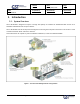
Version Date 1.1 Title January 28th, 2019 Prepared by Reviewed by USER MANUAL 3. System Design 3.1. Perspective View Fan may be used as an option if A is installed in an enclosed space. Figure 2. GST-IC-ELITE-TNR Perspective View © 2019 GS Teletech Inc.
Version Date 1.1 Title January 28th, 2019 Prepared by Reviewed by USER MANUAL 3.2. Exterior View Figure 3. GST-IC-ELITE-TNR Exterior View © 2019 GS Teletech Inc.
Version Date 1.1 Title Page January 28th, 2019 Prepared by Reviewed by 13/ 49 Approved by USER MANUAL 3.3. Interior View (Indoor) Figure 4.
Version Date 1.1 Title Page January 28th, 2019 Prepared by 14/ 49 Reviewed by Approved by USER MANUAL 3.4. External Interface (Indoor & Outdoor) Figure 5. GST-IC-ELITE-TNR External Interface No NAMES DESCRIPTION SPECIFICATION 1 AC IN AC Power Input Port MS22-2-3P 2 RJ-45 Local Maintenance or communication other equipment of GST Local: RJ-45 3 RET Remote Antenna Control Port (AISG 2.0) SU20SPR-8S/ 29V_1.
Version Date 1.1 Title Page January 28th, 2019 Prepared by Reviewed by 15/ 49 Approved by USER MANUAL 4. System Specification 4.1. RF Performance Parameter Frequency Range Input Range Output Power Channel Capacity Gain Range Adjust Step Accuracy Ripple Roll off EVM Frequency Error System Delay Noise Figure VSWR ACLR Spurious Emission Downlink Uplink 2496.3 ~ 2690MHz @ 100KHz Step -65dBm ~ -35dBm/Service -65dBm ~ -35dBm/Service +30dBm (1W) for LTE +30dBm (1W) max.
Version Date 1.1 Title Page January 28th, 2019 Prepared by Reviewed by 16/ 49 Approved by USER MANUAL 4.2. ICS General Performance No. Parameter Condition Specification 1 Gain Re-Tracking Time after reset Target Gain ±1dB < 30 Sec 2 Isolation Sensing Range -10dB < Gain < 10dB Accuracy ±2 3 G = I + 10dB Static General Operating 4 G = I 10Hz Fast Fading Table 4. GST-IC-ELITE-TNR ICS General Performance 4.3. CH Capacity Information 4.3.1.
Version Date 1.1 Title Page January 28th, 2019 Prepared by Reviewed by 17/ 49 Approved by USER MANUAL Channel Frequency CH Name Start(MHz) Center(MHz) Stop(MHz) L33 2633.1 2642.1 L34 2652.9 L38 BW(MHz) EARFCN 2651.1 18 41111 2661.9 2670.9 18 41309 2636.6 2645.6 2654.6 18 41146 L39 2656.4 2665.4 2674.4 18 41344 L53 2631.4 2640.4 2649.4 18 41094 L54 2651.2 2660.2 2669.2 18 41292 L55 2671.0 2680.0 2689.0 18 41490 Table 5.
Version Date 1.1 Title Page January 28th, 2019 Prepared by 18/ 49 Reviewed by Approved by USER MANUAL 4.5. Configuration & Mechanical Specification Parameter Donor/ Service Antenna Filter Specification Remark Band Pass type for LTE & NR Time Division AC Input Voltage: 110~240V (50/60Hz) Power Supply DC Output Voltage: +29V / +6V Operation Temperature -30°C~+50°C (100%RH) Storage Temperature -40°C~+85°C (5~95%RH) Antenna: 4.
Version Date 1.1 Title Page January 28th, 2019 Prepared by Reviewed by 19/ 49 Approved by USER MANUAL 5. System Block Configuration 5.1. RF Signal Flow (Indoor) Figure 6.
Version Date 1.1 Title Page January 28th, 2019 Prepared by 20/ 49 Reviewed by Approved by USER MANUAL Figure 7. GST-IC-ELITE-TNR Signal and Data Flow(Indoor) No Data signal Flow No Data signal Flow 1 DL AMP <-> DFM (LvTTL) 6 Service Switch Control <-> DFM 2 UL AMP <-> DFM 7 Fan Control <-> DFM 3 SMPS Alarm <-> DFM 8 LED Board <-> SNMP Board 4 DFM <-> SNMP Board(LvTTL) 9 RET Control Data 5 Donor Switch Control <-> DFM 10 - Table 9.
Version Date 1.1 Title Page January 28th, 2019 Prepared by Reviewed by 21/ 49 Approved by USER MANUAL 5.3. Power Supply Flow Figure 8.
Version Date 1.1 Title Page January 28th, 2019 Prepared by Reviewed by 22/ 49 Approved by USER MANUAL 6. Status/ Control & Alarm Monitoring 6.1. Status Monitoring and Control Parameters • In case of control parameter, present status but also setting value display on Web-UI.
Version Date 1.1 Title Page January 28th, 2019 Prepared by 23/ 49 Reviewed by Approved by USER MANUAL Parameter Status Donor Site ID Temp Control Description ○ Write the Donor Site Info. That install a repeater Current Temperature in repeater ○ Temp. High Limit ○ Control Temp.
Version Date 1.
Version Date 1.1 Title Page January 28th, 2019 Prepared by Reviewed by 25/ 49 Approved by USER MANUAL 7. Web-UI Overview • Provide all functions that can be performed at the local craft port will be available thru the remote interface • Support the GUI pages that will be addressable via the LTE/ CDMA wireless modem • Support Remote access that will enable troubleshooting down to a specific location 7.1.
Version Date 1.1 Title January 28th, 2019 Prepared by Reviewed by Page 26/ 49 Approved by USER MANUAL 7.2. Login-In Screen • Web-UI Screen for Log-In • After Logging, User can be able to operate Web-UI • Register & Delete a User name/ Password: Refer to 8.6 User Management • Display Total Alarm & Shutdown Status • Enter the IP Address "192.168.1.1" into your browser address bar and you will be redirected to the Login page Write a Use ID and Password Figure 10.
Version Date 1.1 Title January 28th, 2019 Prepared by Reviewed by USER MANUAL 7.3. RF Status & Control • Web-UI Screen for display Repeater’s RF Status & Control window Figure 11. RF Status monitoring & Control © 2019 GS Teletech Inc.
Version Date 1.1 Title January 28th, 2019 Prepared by Reviewed by Page 28/ 49 Approved by USER MANUAL 7.4. Alarm Configuration • Web-UI Screen for Alarm Configurations • Decide to activate an each alarm • When "Report Alarm" is OFF, all alarms are disabled. When "Report Alarm" is ON, alarms can be Enable/ disabled individually Figure 12. System Alarm Configurations © 2019 GS Teletech Inc.
Version Date 1.1 Title January 28th, 2019 Prepared by Reviewed by Page 29/ 49 Approved by USER MANUAL 7.5. Communication Configuration • Web-UI Screen for Communication Configurations • Set the information in order to connect to Sprint Server • On this page you can change the various values related to IP network. Because the Web-UI is based on the IP network, incorrect configuration may make it impossible to connect to the Web-UI.
Version Date 1.1 Title January 28th, 2019 Prepared by Reviewed by Page 30/ 49 Approved by USER MANUAL 7.6.
Version Date 1.1 Title January 28th, 2019 Prepared by Reviewed by Page 31/ 49 Approved by USER MANUAL 7.7. Alarm Log • Web-UI Screen for finding Alarm log • You can see the history of reported and reset Alarms.
Version Date 1.1 Title January 28th, 2019 Prepared by Reviewed by USER MANUAL 7.8. Log • Web-UI Screen for reading a List of operation history • Logs will maintain a history of up to 30 cycles Figure 16. The way to read a Log History © 2019 GS Teletech Inc.
Version Date 1.1 Title January 28th, 2019 Prepared by Reviewed by Page 33/ 49 Approved by USER MANUAL 7.9. Troubleshooting • Web-UI Screen for informing a contact information in case of occurring Field Troubleshooting Figure 17. The information of Contact point in case of occurring Field Troubleshooting © 2019 GS Teletech Inc.
Version Date 1.1 Title January 28th, 2019 Prepared by Reviewed by Page 34/ 49 Approved by USER MANUAL 7.10. Software Update • Web-UI Screen for downloading a software • Procedure 1) Go to "Remote Software Upgrade" link 2) Click Browse button to select the upgrade file from the laptop 3) Choose the file to upgrade. Provided by manufacturer.
Version Date 1.1 Title January 28th, 2019 Prepared by Reviewed by Page 35/ 49 Approved by USER MANUAL 7.11. System Reset • Web-UI Screen for resetting the system • Click on the desired reset action • Clink "Yes" to reset the repeater via a soft-boot. This will not change any of the current settings Figure 19. The way to reset the system using the Web-UI © 2019 GS Teletech Inc.
Version Date 1.1 Title January 28th, 2019 Prepared by Reviewed by USER MANUAL 7.12. Factory Default Setting • Web-UI Screen for Default Setting before operating Figure 20. The way to restore Factory Default Setting for repeater © 2019 GS Teletech Inc.
Version Date 1.1 Title January 28th, 2019 Prepared by Reviewed by Page 37/ 49 Approved by USER MANUAL 7.13. Configuration Transfer • Web-UI Screen for mutual information transfer between Repeater and Local Craft Figure 21. The way to down/ up load configuration between laptop and repeater © 2019 GS Teletech Inc.
Version Date 1.1 Title January 28th, 2019 Prepared by Reviewed by Page 38/ 49 Approved by USER MANUAL 8.
Version Date 1.1 Title January 28th, 2019 Prepared by Reviewed by Page 39/ 49 Approved by USER MANUAL 8.1. Warnings and Hazards 8.1.1. Electric Shock • Opening the Repeater could result in electrical shock and may cause severe injury • Operating the Repeater with antennas in very close proximity facing each other could lead to severe damage to the repeater 8.1.2.
Version Date 1.1 Title Page January 28th, 2019 Prepared by Reviewed by 40/ 49 Approved by USER MANUAL 8.2. Cabling The cabling diagram of the GST-IC-ELITE TNR-Indoor is as follows Figure 22. GST-IC-ELITE-TNR-Indoor Cabling Diagram From To Cable MGB Frame Ground Cable: AWG 6/ 6ft Circuit Breaker Box AC Power Cable: AWG 16/ 6ft GST-IC-ELITE TNR RF Antenna Feeder Cable: 1/2 inch Feeder Line RF Antennas RET control Cable (option) Table 14.
Version Date 1.1 Title January 28th, 2019 Prepared by Reviewed by Page 41/ 49 Approved by USER MANUAL No use for the unauthorized device When installing the system, must check the devices that use is authorized. This conditions apply antenna, cable and coupling device if necessary. Circuit Breaker Installation in the Box for Overcurrent Protection Must install the circuit breaker between the system and main AC source for separating.
Version Date 1.1 Title January 28th, 2019 Prepared by Reviewed by USER MANUAL 8.3. Installation Guide for Crew 8.3.1. Wall Mount Installation The procedure for fixing the wall type system is as follows: 1) Wall Mounting Bracket Shape Figure 23. Mounting Bracket Shape © 2019 GS Teletech Inc.
Version Date 1.1 Title January 28th, 2019 Prepared by Reviewed by Page 43/ 49 Approved by USER MANUAL 2) To mount the system on the wall, first fix the bracket on the wanted position Figure 24. Fixing the Bracket for installing a Wall Mount Wall Thickness Wall thickness to fix the system is 1.5 inch over at least. © 2019 GS Teletech Inc.
Version Date 1.1 Title January 28th, 2019 Prepared by Reviewed by Page 44/ 49 Approved by USER MANUAL 3) Hang the system to the hooking position at the top of the mounting bracket Figure 25. The way to hang the system for Wall Mounting 4) Align the system with the fixing holes of the mounting bracket and fix them firmly Figure 26. The way to fix firmly the System for Wall Mounting © 2019 GS Teletech Inc.
Version Date 1.1 Title Page January 28th, 2019 Prepared by 45/ 49 Reviewed by Approved by USER MANUAL 8.4. Cable Connection 8.4.1. AC Power cable connection • Repeater supports a free AC Input voltage from 110V to 220V • The pin description of AC Port is below. User should connect exact polarity of AC Port Outlook (Fixed Side) Port numbering NAME Description A AC_H AC Hot B AC_N AC Neutral C F.G Frame Ground MS-3102A-10SL-3P Table 15. AC Power Connector Configuration 8.4.2.
Version Date 1.1 Title Page January 28th, 2019 Prepared by 46/ 49 Reviewed by Approved by USER MANUAL 8.4.3. RET Cable Connection (Option) Port Outlook (Fixed Side) SU20SPR-8S Port numbering NAME Description 3 RS485B Communication 4 DGND Frame Ground 5 RS485A Communication 6 +29 V 1.5A max 7 DC Return Retune DC Power 1, 2, 8 NC - Table 17. GST-IC-ELIT TNR RET Cable Connection 8.4.4.
Version Date 1.1 Title January 28th, 2019 Prepared by Reviewed by Page 47/ 49 Approved by USER MANUAL 8.4.5. Grounding cable Connection • JOCT 0202-RL05 Lug supports AWG #6. The way to install the grounding cable is below Frame Ground Figure 28. The way to install the Frame Ground Cable and Lug specifications © 2019 GS Teletech Inc.
Version Date 1.1 Title January 28th, 2019 Prepared by Reviewed by Page 48/ 49 Approved by USER MANUAL 9. FCC Warning Statement FCC Part 15.105 statement This equipment has been tested and found to comply with the limits for a Class A digital device, pursuant to part 15 of the FCC Rules. These limits are designed to provide reasonable protection against harmful interference when the equipment is operated in a commercial environment.
Version Date 1.1 Title January 28th, 2019 Prepared by Reviewed by Page 49/ 49 Approved by USER MANUAL Supplier's Declaration of Conformity 47 CFR § 2.1077 Compliance Information Unique Identifier: IC-ELITE TNR33 Responsible Party – U.S. Contact Information GSTeletech,Inc. 8206 Marshall Drive, Lenexa, Kansas 66214 Contact point Charles You chyu@gsteletechinc.com Office : 1-913-469-6699 Fax : 1-913-661-0163 FCC Compliance Statement (e.g.