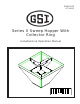
PNEG-970 07-14-05 Series II Sweep Hopper With Collector Ring Installation & Operation Manual PNEG-970
Catalog No. Slip Ring Serial No. Date of Purchase The manufacturer reserves the right to improve its product whenever possible and practical to do so. We reserve the right to change, improve, and modify products at any time without obligation to make changes, improvements, and modifications on equipment sold previously.
Table of Contents Personnel operating or working around this equipment should read this manual. This manual must be delivered with equipment to its owner. Failure to read this manual and its safety instructions is a misuse of the equipment. Any misuse of the equipment may void the warranty. 1. Safety .................................................................................. 4 2. Introduction ...................................................................... 13 3. Assembly .....................
Safety SAFETY GSI equipment is built to provide many years of dependable service to our customers through durable craftsmanship. One of the most important aspects of GSI engineering is SAFETY 1st design throughout all product lines. At GSI - safety is NO ACCIDENT! That is why GSI is implementing its SAFETY 1st program.
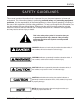
Safety SAFETY GUIDELINES This manual contains information that is important for you, the owner/operator, to know and understand. This information relates to protecting personal safety and preventing equipment problems. It is the responsibility of the owner/operator to inform anyone operating or working in the area of this equipment of these safety guidelines. To help you recognize this information, we use the symbols that are defined below. Please read the manual and pay attention to these sections.
Safety Safety Instructions GSI’s principle concern is your safety and the safety of others associated with grain handling equipment. We want to keep you as a customer. This manual is to help you understand safe operating procedures and some problems which may be encountered by the operator and other personnel. As owner and/or operator, it is your responsibility to know what requirements, hazards and precautions exist, and to inform all personnel associated with the equipment or in the area.
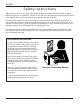
Safety ROTATING FLIGHT Grain augers can kill or dismember. DANGER! Rotating Flight Keep clear of all augers and never enter the bin unless all power is disconnected and locked out. Failure to do so will result in serious injury or death! OPERATE UNLOAD EQUIPMENT PROPERLY Make sure ALL equipment is locked in position before operating. NEVER start equipment until ALL persons are clear of the work area.
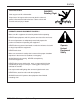
Safety INSTALL & OPERATE ELECTRICAL EQUIPMENT PROPERLY Electrical controls should be installed by a qualified electrician and must meet the standards set by the national electrical code and all local and state codes. Electric Shock Hazard Disconnect and lock out all power sources before installing wires/cables or servicing equipment. ELECTRICAL WARNINGS A. Install and ground the slip ring and the entire unit in accordance with the National Electric Code and local codes and/or ordinances. B.
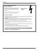
Safety PREPARE FOR EMERGENCIES Be prepared if fire starts. Keep a first aid kit and fire extinguisher handy. Keep emergency numbers for doctors, ambulance service, hospital, and fire department near your telephone. Keep Emergency Equipment Quickly Accessible. WEAR PROTECTIVE CLOTHING Wear close fitting clothing and safety equipment appropriate to the job. Safety glasses should be worn at all times to protect eyes from debris.
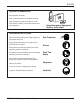
Safety Decals A. The images below show the location of the decals and safety signs which should appear on the Series II Sweep hopper with collector ring. Decal “D” (DC-1224) on top of collector ring shield plate Decal “D” (DC-1224) on side of collector ring shield Decal “A” Location: Size: Part No.: 10 Top of shield plate and side of shield. 2 7/8” x 5” DC-1224 Please remember safety signs provide important safety information for people working near bin unloading equipment that is in operation.
Safety Decals (cont.) A. DANGER Sign No. DC-1395 was supplied with your bin unloading equipment. This safety sign should be applied to the side of the bin near the bin opening, so it will be viewed by people entering into the bin storage building. Do not cover any safety signs or any other signs that are already there. B.
Safety 7. Operator Qualifications. A. The User/Operator must be competent and experienced to operate auger equipment. Anyone who works with or around augers must have good common sense in order to be qualified. These persons must also know and meet all other qualifications, such as: 1. Any person who has not read and/or does not understand all operation and safety instructions is not qualified to operate any auger systems. 2. Certain regulations apply to personnel operating power machinery.
Introduction 1. Product Information A. The Series II Sweep Hopper with Collector Ring includes the following components: - hopper - collector ring - center brace support - collector ring shield NEVER enter a grain bin unless ALL power driven equipment has been shutdown. Disconnect and lockout power before entering the bin or servicing the equipment. 2. General information. A. GSI reserves the right to improve its product whenever possible and practical to do so.
Introduction 4. Slip Ring Information Slip rings must be enclosed and protected from any contact by personnel. Means for the provision of this protection is the responsibility of the user. Various enclosure styles are available from Insul-8. Specifications & Listings A. R-Series Slip Ring products are built to UL specifications but are not generally certified or listed by any independent certifying or regulatory body. B. The following specifications apply to all RSeries Slip Rings: 1.
Assembly 1. ASSEMBLE THE CROSSBRACE A. Assemble the 1" x 9 3/8" conduit to the 1" chase nipple using one (1) 1" conduit coupling. B. Feed the nine (9) stranded wires from the collector ring through the conduit assembly and fasten it to the collector ring.
Assembly 1. ASSEMBLE THE CROSSBRACE (cont.) C. Feed the nine (9) stranded wires from the collector ring through the pivot tube and bolt the collector ring to the crossbrace assembly using four (4) 1/4"-20 x 1" hex bolts, lock washers, and hex nuts.
Assembly 1. ASSEMBLE THE CROSSBRACE (cont.) D. Bolt the collector ring shield to the crossbrace assembly using four (4) 1/4"-20 x 1" hex bolts, flat washers, lock washers, and hex nuts. Do not use the remaining bolts.
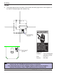
Assembly 1. ASSEMBLE THE CROSSBRACE (cont.) E. Slide the lower tube assembly into the shield assembly. Bolt the crossbrace to the hopper using four (4) 1/2"-13 x 1 3/4" hex bolts, flat washers, lock washers, and hex nuts (One on each side.). crossbrace assembly hex nut lock washer hopper lower tube assembly flat washer 1/2"-13 x 1 3/4" hex bolt F. Slide the lower tube assembly against the hopper and mark the center. G.
Assembly 2. WIRE THE COLLECTOR RING Electrical controls and wiring should be installed by a qualified electrician. The motor disconnect switches and conductor cables should comply with the National Electrical code and any local codes which apply. Reset and motor starting stations should be located so that the operator can see that all personnel are clear of the equipment. Note:The liquid-tight flex conduit may need to be trimmed to length. A.
Assembly 2. WIRE THE COLLECTOR RING (cont.) F. Wire the multi-conductor cord to the collector ring using the fork terminals provided in the following manner. 1. Thermal Protection Leads a. Wire the "P1" lead from the control panel to ring "1". b. Wire the "P2" lead from the control panel to ring "2". 2. Drive Motor Leads a. Wire the three (3) power leads to rings "3", "4", and "5". b. Wire the ground lead to ring "9". 3. Auger Motor Leads a. Wire the three (3) power leads to rings "6", "7", and "8". b.
Assembly 3. ASSEMBLE THE CROSSBRACE TO THE HOPPER A. Feed the multi-conductor cord through the collector ring shield, lower tube assembly, and drilled hole in hopper side. B. Bolt the collector ring shield to the crossbrace assembly using sixteen (16) 1/4"-20 x 1" hex bolts, flat washers, lock washers, and hex nuts. C. Slide the lower tube assembly into the shield assembly.
Assembly 3. ASSEMBLE THE CROSSBRACE TO THE HOPPER (cont.) D. Making sure the lower tube assembly and drilled hole are aligned, bolt the crossbrace to the hopper using eight (8) 1/2"-13 x 1 3/4" hex bolts, flat washers, lock washers, and hex nuts. crossbrace assembly hopper hex nut lock washer 1/2"-13 x 1 3/4" hex bolt E. Attach the 1" liquid-tight flex conduit coupling on the conduit assembly to the hopper. F. Slide the lower tube weldment against the hopper and tack weld into position.
Assembly 4. ASSEMBLE THE CROSSBRACE TO THE SWEEP A. Feed the nine (9) stranded wires from the collector ring through the pivot tube and hole in the back of the sweep head section. B. Align the hole in the backshield with the pivot tube and push the sweep onto the pivot tube.
Assembly 3. ASSEMBLE THE CROSSBRACE TO THE SWEEP (cont.) C. Connect the pivot plate to the backshield using two (2) 1/2"-13 x 1 3/4" hex bolts, flat washers, lockwashers, and hex nuts. D. Fasten the pivot rod to the backshield and pivot plate using two (2) 1/2"-13 x 2" hex bolts, lockwashers, and hex nuts. E. Screw the 45 degree grease fitting into the crossbrace assembly.
Assembly 3. WIRE THE COLLECTOR RING TO THE SWEEP A. Attach one(1) 1" liquid-tight flex conduit coupling to each end of the 1" x 48" liquid-tight flex conduit. B. Feed the nine (9) stranded wires from the collector ring through the 1" conduit coupling and 1" x 48" liquid-tight flex conduit assembly. C. Attach the 1" x 48" liquid-tight flex conduit assembly to the pivot tube using the 1" conduit coupling. 1" flex conduit coupling pivot tube 1" conduit coupling 1" x 48" flex conduit D.
Assembly 3. WIRE THE COLLECTOR RING TO THE SWEEP (cont.) F. Wire the nine (9) stranded wires to the junction boxes in the following manner. 1. Thermal Protection Leads a. b. Wire the "P1" lead from both motors to "1". Wire the "P2" lead from both motors to "2". 2. Drive Motor Leads a. b. Wire the three (3) power leads to "3", "4", and "5". Wire the ground lead to "9". 3. Auger Motor Leads a. b. 26 Wire the three (3) power leads to "6", "7", and "8". Wire the ground lead to "9".
Start-Up 1. Preform Pre-Start Checks Warning! To ensure that the drive is not unexpectedly started, turn off and lock out or tag out the power source before proceeding. Failure to observe these precautions could result in bodily injury. Danger! Failure to perform any or all of these pre-start checks may cause damage to the equipment and/or cause SERIOUS INJURY or DEATH to those in the work area. Failure to perform any or all of these pre-start checks may also be a misuse of the equipment.
Maintenance 1. Maintain the Hopper ALWAYS shutdown and disconnect the power supply before adjusting, servicing or cleaning the equipment. A. Use caution when repairing or replacing equipment parts. B. Make sure ALL decals are legible and tightly attached to the hopper. If necessary, replace them FREE OF CHARGE by contacting GSI at: GSI P.O. Box 20 1004 E. Illinois St. Assumption, IL 62510 (217) 226-4421 C. Make sure ALL electrical wiring is not damaged, and that it meets proper wiring codes. D.
Maintenance 2. Collector Ring Maintenance 3. To remove and replace the brush: a) remove the clamp screw from the brush holder A. Lubrication 1. All bearings are lubricated for life at the factory. Additional lubrication should not be required. 2. CAUTION: Do not apply any lubricants or solvent cleaning agents to any part of the slip ring. b) remove the screw from the brush lead c) remove the brush holder d) replace the brush e) reassemble. B. Brush Holders E. Brush Fit Inspection 1.
Maintenance 2. Collector Ring Maintenance (Cont.) G. Rings 1. Inspect the ring surface for dirt, oxidation, or other contaminants. A properly operating ring will have a film that appears burnished in color with a darker surrounding color where the brushes track. If the ring requires cleaning, order Slip Ring Polishing Kit #41286. H. Electrical Connections 1. Inspect all electrical connections for corrosion and tightness. Clean corroded parts with a wire brush and/or muriatic acid.
Troubleshooting Problem 1. Sweep will not run. Possible Cause Solution A. Power cords may be unplugged. A1. Plug in the power cords. B. Foot switch may not be actuated. B1. Make sure the foot switch is depressed and the switch is operating properly. C. Overloads may be tripped. C1. Reset the overloads. D. The collector ring may not be D1. Check the collector ring making good connections. terminals for proper contact. D2.
Parts 12" HOPPER COMPONENTS 13 5 14 10 5 15 12 10 11 9 8 7 6 4 5 3 2 1 32 PNEG-970 S2 Hopper w/ Collector Ring
Parts 12" & 16" HOPPER COMPONENTS Ref.
Parts Collector Ring Replacement Parts 7.
WARRANTY THE GSI GROUP, INC. ("GSI") WARRANTS ALL PRODUCTS MANUFACTURED BY GSI TO BE FREE OF DEFECTS IN MATERIAL AND WORKMANSHIP UNDER NORMAL USAGE AND CONDITIONS FOR A PERIOD OF 12 MONTHS AFTER RETAIL SALE TO THE ORIGINAL END USER OF SUCH PRODUCTS. GSI'S ONLY OBLIGATION IS, AND PURCHASER'S SOLE REMEDY SHALL BE FOR GSI, TO REPAIR OR REPLACE, AT GSI'S OPTION AND EXPENSE, PRODUCTS THAT, IN GSI'S SOLE JUDGMENT, CONTAIN A MATERIAL DEFECT DUE TO MATERIALS OR WORKMANSHIP.
THIS EQUIPMENT SHALL BE INSTALLED IN ACCORDANCE WITH THE CURRENT INSTALLATION CODES AND APPLICABLE REGULATIONS WHICH SHOULD BE CAREFULLY FOLLOWED IN ALL CASES. AUTHORITIES HAVING JURISDICTION SHOULD BE CONSULTED BEFORE INSTALLATIONS ARE MADE. P.O. Box 20 1004 E. IL. St Assumption IL.