
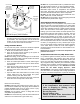
Inc. INSTALLATION AND OPERATING INSTRUCTIONS FLAMMABLE VAPOUR IGNITION RESISTANT POWER VENTED WATER HEATER 5065


Venting
This water heater has a power vent system that discharges
all it's combustion products outdoors. The heater must be
properly vented for removal of exhaust gases. Correct
installation of the vent pipe system is mandatory for the safe
and efficient operation of this water heater and is an impor-
tant factor in the life of the unit.
Vent pipe must be installed in accordance with all local and
provincial or state codes or, in the absence of such, the lat-
est edition of "Natural Gas and Propane Installation
Code" CAN/CSA-B149.1 (Canada), or "National Fuel Gas
Code" ANSI Z223.1 (NFPA 54) (U.S.A.).
Note: Do not common vent this water heater with any other
appliance. Do not install in the same chase or chimney with
a metal or high-temperature plastic from another gas or fuel
burning appliance.
Vent Pipe Material
• This heater has been certified to use Schedule 40 ABS,
PVC or CPVC venting material.
•
Check local codes to determine which materials are
allowed in your area.
• Use only solid (not foam core) piping. All materials must
be of the same type for any given installation and must
be joined with the proper primer/cleaner and solvent
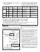
cement. See Table 2 for vent lengths and sizing.
• Canadian installations using PVC venting require the
PVC Vent Conversion Kit P/N 73901 or P/N 73876.
• U.S.A. installations using PVC piping shall use the pipe
assembly adaptor supplied with the heater.
See also “Vent Pipe Connection to Blower”.
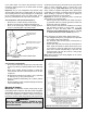
Vent Pipe Termination
A "Rodent Screen" must be installed in the termination
elbow to prevent foreign objects from entering the venting
system. The plastic screens (see Figure 6) supplied with
this water heater are designed for use as the vent termina-
tion "Rodent Screen". Refer to Figures 8 & 9 for information
regarding the vent termination. After determining the total
equivalent length of vent pipe for your installation, (see
Table 2), use the appropriate "Rodent Screen" to obtain the
best possible efficiency. Install only one of the two options
listed in Figure 6.
1. Drill a hole through the exterior wall, slightly larger than
the vent piping, to allow for final alignment of the vent
piping to the heater.
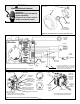
2. Install "Rodent Screen" in the termination elbow as
shown in Figure 7 and fasten in place using silicone
sealant.
Note: Apply only enough sealant to hold the screen in place
inside the termination elbow. This will allow for annual
screen removal, inspection and cleaning of the vent pipe
system of any lint or debris.
3. Fit the termination elbow to a short length of vent pipe
600mm (2 ft.) min., 1.5m (5 ft.) max. and join with sol-
vent cement.
4. Push this termination assembly through the wall from
the outside until the joint with the elbow is within 25mm
- 50mm (1 in. - 2 in.) of the outside face of the wall.
5. Point the elbow down and temporarily hold the assem-
bly in position with a small wedge or a splinter of wood.
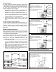
If a Vent Riser is Required
1. Fabricate the vent riser to lift the termination elbow to
the height required.
2. Fasten the vent riser assembly to the outside wall with
brackets (see Figure 9). Brackets to be supplied by
installer.
3. Extend the horizontal run of pipe a convenient distance
through the wall to make further work easy.
4. Connect the vent riser assembly to the rest of the vent-
ing system.
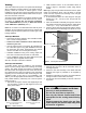
VENT LENGTH LESS THAN OR
EQUAL TO 20 EQUIVALENT FEET
USE THIS SCREEN.
VENT LENGTH GREATER THAN 20
EQUIVALENT FEET USE THIS
SCREEN.
Figure 6 Rodent Screens
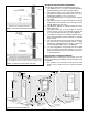
OUTSIDE OF
DWELLING
TERMINATION ELBOW
INSIDE OF
DWELLING
RODENT SCREEN
VENT PIPE TO WATER HEATER
Figure 7 Vent System Termination
SILICONE SEALANT
CAUTION:
Use of Solvent Cement and Primer
• Use only in well-ventilated areas.
• Do not use near flame or open fire.
• Use only the Solvent Cement and Primer
appropriate for the venting material being
used.
• Solvent cements for plastic pipe are flam-
mable liquids and must be kept away from
all sources of ignition.
– 11 –