
Inc. INSTALLATION AND OPERATING INSTRUCTIONS FLAMMABLE VAPOUR IGNITION RESISTANT POWER VENTED WATER HEATER 5065
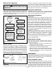

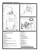

IX) PARTS REFERENCE ILLUSTRATION
17
16
14
15
13
12
10
11
9
8
7
6
1
32
26
25
23
24
22
21
20
19
18
54
31
6
27
28
29
30
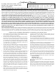
1. Vent Termination Elbow with Rodent Screen
2. **Vent Pipe
3. **Vent Pipe Coupling (if required)
4. **Vent Pipe Elbow (long radius)
5. Limit Switch
6. T&P Valve
7. Diptube
8. Baffle Assembly
9. Driptube
10. Gas Control/Thermostat
11. Gas Control/Thermostat Cover
12. Drain Valve
13. Outer Gas Door
14. Manifold Door Assembly (behind outer door)
15. Floor Drain
16. **Drain Pan
17. Flammable Vapour Sensor (under cover)
18. Combo Heating System Return Inlet (Optional)
19. Air Inlet Snorkel
20. Combo Heating System Supply Outlet (Optional)
21. Power Cord
22. Air Switch (inside box)
23. Junction Box
24. Junction Box Cover
25. Air Tubing
26. Rubber Coupling
27. Gear Clamp
28. Draft Diverter
29. Hot Water Outlet Nipple
30. Anode (under cap)
31. Cold Water Inlet Nipple
32. Flexible Manifold Tube
33. Viewport
34. Hot Surface Igniter
35. Gas Orifice
36. Sheet Metal Burner
37. Gas Manifold
38. Flame Sensor Rod
39. Manifold Door Gasket
40. Manifold Door
41. Two Piece Grommet With Clip
** Items not supplied with the water heater
.
Figure 29 Parts Reference
32
33
34
35
41
40
36
37
38
39
FRONT VIEW
REAR VIEW
– 28 –