2500 Series 1 Table of Contents Introduction Installation Switches and Indicators Setting the Soft Switches Selected Applications Software Switch Controlled Parameters Switch Bank Settings 5 7 10 12 14 20 21
500 Series 2 WARNING This equipment generates and uses radio frequency energy and if not installed and used properly, that is, in strict accordance with the manufacturer’s instructions, may cause interference to radio and television reception.
2500 Series 3 WARRANTY Seller makes no warranties except as set forth herein. Seller warrants that articles furnished hereunder are free from defects in material and workmanship and perform to applicable published CalComp specifications. This warranty is in lieu of any other warranty expressed or implied. In no event will seller be liable for special or consequential damages as a result of any alleged breach of this warranty provision.
2500 Series 4
2500 Series 5 Introduction The CalComp 2500 Tablet, when used with the appropriate host computer and software, is a means of entering information into the computer. The tablet produces position information which is used by the host and software. A change of software can convert the tablet from a drafting table to a special function keyboard. Tracing existing art or drawing freehand on the tablet’s surface with the cursor or stylus converts the cursor position into digital information for the software.
2500 Series 6 Warnings, Cautions and Notes Warnings: Indicates conditions, practices or procedures which must be followed to avoid injury or loss of life. Cautions: Demonstrates conditions, practices or procedures which must be followed to avoid equipment damage or destruction. Notes: Highlights the information of special importance or interest to the user. Definitions Used in this Manual The top of the tablet is the frame edge with the CALCOMP logo. The bottom is the edge opposite the logo.
2500 Series 7 Installation Before beginning the installation, check the voltage indicator pin at the rear of the tablet to ensure that the voltage is correct for your locale. The indicator pin should appear in the 120 volt position for areas with 100-125 Volts AC and the 240 Volt position for 200-250 Volts AC. Connect the tablet to the host, turn on the power and set the tablet’s soft switches to correspond to the host and software’s requirements.
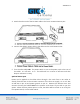
2500 Series 8 3. Attach the other end of the RS-232C cable to the host’s communications port. 4. Connect the tablet’s power cable to the tablet and to a wall power outlet. 5. Turn the 2500 tablet ON. The power switch is next to the power cord at the rear of the tablet. 0 is off and 1 is on. The tablet will run a series of self-tests and then beep to indicate it is ready.
2500 Series 9 NOTE: Damage to the host may result if the tablet is operated with the AC line cord connected and the W3 jumper installed. Use either option, not both. The tablet uses magnetic coupling to detect the position of the cursor. The performance may be degraded (excessive jitter) by the presence of strong magnetic fields produced by AC sources. Potential sources of AC magnetic fields include some television sets and monitors with minimum shielding around the horizontal sweep circuits.
2500 Series 10 Switches and Indicators The Tablet-Status Display blocks across the top of the tablet have multiple functions. In operating mode, the numbered indicators light to inform the operator of the tablet’s activities. In self-test mode, the lights indicate which test failed. In set-up mode, the blocks become “switches” that are used to set operating parameters. The indicators may be used by some programs to indicate special functions.
2500 Series 11 Handshake Lights when host generated handshaking prevents tablet transmission. Disable Lights when tablet is in HALT mode, X-OFF has been selected or the RS-232 communications port is disabled. The other three indicators light to indicate whether the tablet is in TEST mode or the switch selecting and setting mode. TEST Lights when tablet is in TEST mode. Flashes if the tablet has failed one of the self-tests on power up. SETUP Lights in SETUP mode. Soft switches can be set.
2500 Series 12 Setting the Soft Switches During installation, the numbered display blocks act as switches that must be set to select operating parameters for the tablet. There are eight banks of eight switches. The first five banks must be set to operate with your software. Activate each bank in turn, setting the switches as indicated in the tables on the following pages. The number 1 indicates that the switch light must be on and the number 0 specifies that the light must be off. 1. Select the BANK block.
2500 Series 13 5. Repeat steps 1 through 4, selecting new banks and setting the switches until all the necessary switches have been set. Remember to change banks. 6. To go back to operating mode, select the SETUP block again after setting the last bank of switches instead of the BANK block. Neither the BANK nor the SETUP block lights should be on. The switches will maintain their settings when the tablet is turned off or unplugged unless this session only is selected as the default setting in Bank One.
2500 Series 14 NOTE: If frequent changing of soft switch settings is required, one set of parameters may be saved in memory and recalled whenever the restore baseline settings soft switch in Bank Seven is selected. Save the most frequently used settings. Selected Applications Software The setting of Bank 5, switch 2 is dependent on the interface cables and the host’s interface requirements. The switch determines whether the tablet transmits on pin 2 or 3 of the RS232C interface.
2500 Series 15 AUTOCAD WITH CALCOMP 2000 EMULATION AUTOCAD WITH SUMMAGRAPHICS BIT PAD ONE EMULATION SWITCH 1 2 3 4 5 6 7 BANK #1 0 0 0 0 0 0 0 BANK #2 0 1 0 0 1 0 0 BANK #3 0 0 0 1 1 1 0 BANK #4 0 0 1 0 0 0 0 BANK #5 0 * 0 1 0 1 0 *Setting of switch 2, Bank 5 may be either 0 or 1.
2500 Series 16 AUTOCAD WITH HITACHI TIGER HDG-1111 EMULATION SWITCH BANK #1 BANK #2 BANK #3 BANK #4 BANK #5 1 0 0 0 0 0 2 0 1 1 0 * 3 0 0 1 1 0 4 0 0 0 0 1 5 0 1 1 0 0 6 0 1 1 0 1 7 0 0 0 0 0 8 1 0 0 1 0 7 0 0 0 0 0 8 1 0 0 1 0 7 0 0 0 0 0 8 1 0 0 1 0 7 0 0 0 0 0 8 1 0 0 0 0 PERSONAL DESIGNER WITH KURTA EMULATION SWITCH BANK #1 BANK #2 BANK #3 BANK #4 BANK #5 1 0 0 0 0 0 2 0 0 0 0 * 3 0 1 0 1 0 4 0 0 1 0 1 5 0 1 1 1 0 6 0 0 1 0 1 VERSACAD WITH CALCOMP 2000 EMULATION SWITCH BANK #1 BAN
2500 Series 17 CAD KEY WITH SUMMA BIT PAD ONE EMULATION SWITCH 1 2 3 BANK #1 0 0 0 BANK #2 0 1 0 BANK #3 0 0 0 BANK #4 0 0 1 BANK #5 0 1 0 *Setting of switch 2, Bank 5 may be either 1 or 0.
2500 Series 18 POINT LINE WITH CALCOMP 2000 EMULATION SWITCH 1 2 3 BANK #1 0 0 0 BANK #2 0 1 0 BANK #3 0 0 0 BANK #4 0 0 1 BANK #5 0 1 0 *Setting of switch 2, Bank 5 may be either 1 or 0. 4 0 0 1 1 1 5 0 0 1 1 0 6 0 0 1 1 1 7 0 0 0 0 0 8 1 0 0 0 0 Other Software If the software you will be using was not listed, follow the instructions below. Check the software manual for the baud rate, data bits, start bits, stop bits, parity, line feed, data rate, operating mode and resolution it expects.
2500 Series 19 NOTES: Most software for personal computers will work with the tablet provided that the transmit and receive lines are correct. Commands, Bank 2, switch 1 should be enabled if a CalComp format is being operated and disabled if any other format is being used. If the software uses the commands of another manufacturer’s tablet as part of its driver for that tablet, the 2500 will probably not work. Contact the software manufacturer to enquire if a driver for CalComp tablets has been developed.
2500 Series 20 Switch Controlled Parameters The following operating characteristics are controlled by the settings of the soft switch banks. The settings are listed on the page given after the bank number. Parameters which were too complex to explain with a brief phrase have a thorough explanation on the page given after this brief explanation. BANK ONE Effectivity Soft switch settings may be made effective immediately, on reset or for the current session only.
2500 Series 21 BANK FIVE Communications DTE or DCE, handshake and echo. X-ON/X-OFF Enable or disable output. Tablet begins transmitting at power on (XON) or there is no transmission at power on (X-OFF). Commands Enable or disable 16-button cursor commands, 2000 style commands or 9100 style commands. Beeper Enable or disable beeper command acknowledge. BANK SIX, SEVEN AND EIGHT Reset Reset the tablet (software reset). Lamp Test Light all LED indicators.
2500 Series 22 SWITCH 4 0 0 0 0 0 0 0 0 0 0 0 0 0 0 0 0 1 5 0 0 0 0 0 0 0 0 1 1 1 1 1 1 1 1 0 6 0 0 0 0 1 1 1 1 0 0 0 0 1 1 1 1 0 1 1 1 7 0 0 1 1 0 0 1 1 0 0 1 1 0 0 1 1 0 8 0 1 0 1 0 1 0 1 0 1 0 1 0 1 0 1 0 OPERATING MODE POINT RUN TRACK LINE PROMPT POINT PROMPT RUN PROMPT TRACK PROMPT LINE HALT INCREMENT RUN INCREMENT TRACK INCREMENT LINE DELTA POINT DELTA RUN DELTA TRACK DELTA LINE RESERVED 1 1 RESERVED TO Bank 2 Output SWITCH 1 0 1 COMMANDS* DISABLED ENABLED NOTE: Commands must be enab
2500 Series 23 SWITCH 2 3 4 5 0 0 0 0 0 0 0 0 1 1 1 1 0 0 0 0 1 1 1 1 0 0 0 0 0 0 1 1 0 0 1 1 0 0 1 1 0 1 0 1 0 1 0 1 0 1 0 1 DATA RATE (POINTS PER SECOND) 1 5 10 20 33 40 50 75 100 125 MAXIMUM RESERVED 1 1 1 1 RESERVED TO SWITCH 6 0 1 LINE FEED DISABLE ENABLE SWITCH 7 0 1 OUT OF PROXIMITY DATA DISABLE ENABLE SWITCH 8 0 1 MARGIN DATA ENABLE DISABLE
2500 Series 24 Bank 3 Output SWITCH SWITCH 1 0 0 0 0 1 1 1 1 4 0 0 0 0 0 0 0 0 0 0 0 0 0 0 0 0 1 2 0 0 1 1 0 0 1 1 5 0 0 0 0 0 0 0 0 1 1 1 1 1 1 1 1 0 3 0 1 0 1 0 1 0 1 6 0 0 0 0 1 1 1 1 0 0 0 0 1 1 1 1 0 RESOLUTION 200 LPI (LINES/INCH) 400 LPI 500 LPI 1000 LPI 10 LPmm (LINES/MILLIMETER) (254 LPI) 40 LPmm (1016 LPI) 50 LPmm (1270 LPI) 100 LPmm (2540 LPI) (half resolution) 7 0 0 1 1 0 0 1 1 0 0 1 1 0 0 1 1 0 8 0 1 0 1 0 1 0 1 0 1 0 1 0 1 0 1 0 ASCII FORMATS 0 1 2 3 4 5 6 7 8 9 10 11 12 13 14 15 16
00 Series 25 SWITCH SWITCH 4 1 5 0 6 0 7 0 1 4 1 1 1 1 1 1 1 1 1 0 5 0 1 1 1 1 1 1 1 1 1 6 1 0 0 0 0 1 1 1 1 1 7 1 0 0 1 1 0 0 1 1 8 1 TO 0 8 1 0 1 0 1 0 1 0 1 RESERVED FORMATS 17 22 BINARY FORMATS 23 24 25 26 27 28 29 30 31 Bank 4 RS-232 Operation SWITCH 1 0 0 0 0 1 1 1 1 SWITCH SWITCH 2 0 0 1 1 0 0 1 1 3 0 1 0 1 0 1 0 1 BAUD RATE 19200 9600 4800 2400 1200 600 300 RESERVED 4 0 1 7 8 DATA BITS BITS BITS 5 0 1 1 2 STOP BIT (11 BIT FRAME LIMIT) BIT BITS
2500 Series 26 SWITCH 6 0 0 0 0 1 7 0 0 1 1 X 8 0 1 0 1 X PARITY ODD EVEN MARK SPACE DISABLED Bank 5 Special Functions SWITCH 1 0 1 ECHO DISABLED ENABLED SWITCH 2 0 1 DATA LINE ASSIGNMENT DTE (Transmit on pin 2) DCE (Transmit on pin 3) SWITCH 3 0 1 HANDSHAKE CONTROL DISABLED ENABLED SWITCH 4 0 1 X-ON / X-OFF DEFAULT Tablet not transmitting on power up (X-OFF) Tablet transmitting on power up (X-ON) SWITCH 5 0 1 16-BUTTON CURSOR COMMANDS DISABLED ENABLED SWITCH 6 0 1 BEEPER COMMAND ACKN
2500 Series 27 SWITCH 8 0 1 9100 SERIES COMMANDS ENABLED DISABLED NOTE: Bank 2 switch 1 must be enabled before this switch bank may be used to selectively enable or disable command sources.
2500 Series 28 Corporate Headquarters 14557 N. 82nd Street Scottsdale, Arizona 85260 Tel: 1-866-746-3015 Support: 1-866-746-3015 Fax: 480-998-1751 Support: 1.866.746.3015 Copyright© 2014 GTCO CalComp by Turning Technologies, Inc. 2500 Series is a trademark of GTCO CalComp by Turning Technologies, Inc. All other products and company names are the trademarks or registered trademarks of their respective owners. The information contained in this document is subject to change without notice.