MM II 1 Chapter 1 What is the MM II and How Does It Work? Section A: What is the MM II? Section B: How the MM II Works Section C: Commands: Controlling the Tablet’s Operation Section D: Changing the Tablet Set Up 3 3 4 6 6 Chapter 2 Assembly and Installation 7 Chapter 3 Interfacing with the Host Section A: Hardware Interfaces RS-232C Interface TTL Interface Section B: Baud Rate Section C: Communication Protocols Section D: Report Formats Binary Report Format ASCII BCD Report Format 10 10 11 12 12 1
MM II 2 Reset (to Defaults) Send Configuration Tablet Identifier Transmission Control Z Commands Section D: Reserved Commands 30 31 33 34 34 36 Chapter 5 Guidelines for Writing a Device Driver 37 Chapter 6 Using the MM II 42 Chapter 7 Checking the Graphics Tablet Section A: Power/Prox Light Section B: A Quick Functional Check Section C: Diagnostic Functions Code Check Echo Self-Test Send Test Results 43 43 43 44 44 45 45 45 Chapter 8 Operating Environment, Care and Service Section A: Operating
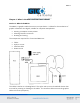
MM II 3 Chapter 1: What is the MM II and How Does It Work? Section A – What is the MM II? The MM II is a graphics tablet that acts as an input device. It allows for the translation of graphic information into digital, suitable for computer manipulation. Steering a computer screen pointer Selecting locations on menus Drawing and tracing The components required for a functional MM II are: Tablet Stylus or cursor Interface cable Power source The tablet is similar to a drawing board.
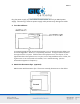
MM II 4 Section B: How the MM II Works MM II translates the stylus/cursor position on the tablet into digital information and communicates it to the host. The stylus/cursor position is expressed as an X, Y coordinate pair. One coordinate pair is a report. Valid reports can only be collected when the stylus/cursor is in the tablet’s active area and in proximity: Active area is an 11.7 inch square area inside the groove on the tablet surface.
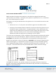
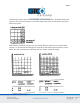
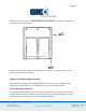
MM II 5 As previously stated, reports are measured in counts of resolution. As shown below, each square is one count of resolution. The tablet reports the same coordinates for any point within the square. With different resolution settings, you can receive different reports for the same tablet location. In the illustration below, points A and B are the same physical locations on the tablet, but their coordinates are different because of the resolution setting.
MM II 6 Reports are in absolute or relative coordinates. Absolute coordinates are coordinates measured from the tablet’s origin (0, 0). Relative coordinates are measured relative to the last report location. In the illustration above, point B is issued after point A. Therefore, in relative coordinates, point B is measured relative to point A. The tablet defaults to absolute coordinates. However, you can change to relative coordinates with the Relative Coordinates command, described in Chapter 4.
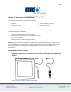
MM II 7 Chapter 2: Assembly and Installation The MM II package should include the following: Tablet Stylus or cursor Interface cable Power supply (optional) Document clips MM II+ Graphics Tablet User’s Guide To assemble and install MM II: 1. 2. 3. 4. Connect the stylus/cursor to the tablet. Attach the tablet to the host and power source. Turn on the tablet. Attach the document clips.
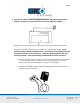
MM II 8 2. Connect the tablet to the host and power source. Plug the interface cable modular connector into the socket at the top left edge of the tablet. Plug the interface cable 25-pin D connector into the host communications port. The tablet can obtain power from the computer or MM II power supply. Never power the tablet from both simultaneously. Pin 9 and the power supply socket are connected inside the 25-pin D connector. Therefore, power applied to one, also exists on the other.
MM II 9 Plug the power supply into a standard electrical outlet. Use only an MM II power supply. Substituting a different power supply could permanently damage the tablet. 3. Turn the tablet on. The power light/prox light serves two purposes. First, it notifies that the tablet is on and receiving power. Second, it is a proximity indicator. The light remains lit when the stylus/cursor is in-prox. It blinks when the stylus/cursor is out-of-prox.
MM II 10 The clips attach to rails on the tablet underside. To attach them, push them straight on or slide them up from the bottom. Position the clips where they’re comfortably out of the way. To remove the clips, slide them to the bottom of the tablet. Chapter 3: Interfacing with the Host For successful communication between MM II and its host, they must have the same hardware interface, baud rate, communications protocol and report format.
MM II 11 The interface accommodates RS-232C and TTL. (Do not use both at the same time.) RS-232C – CITTL Interface: 25-Pin D Connector Pin Assignments Pin 1 2 3 7 9 11 Wire Name GND TXD RXD signal ground +12 VDC TXD Description Protective, frame ground Transmits data to host (RS-232C only) Receives data from host (RS-232C or TTL) Return for data Power to tablet from host Transmits data to host (TTL only) Pin 9 is for powering the tablet from the host.
MM II 12 TTL Interface The computer port must provide full duplex, asynchronous, serial communications. The signal levels for data transmission are: TTL Signal Levels TTL Interface Binary states Signal condition Interchange Voltage 0V to 0.8V 1 Mark +2.4V to +5V 0 Space Section B: Baud Rate The MM II is available with 9600 baud or Autobaud. The standard setting is 9600 baud, unless Autobaud is specifically ordered. Autobaud automatically matches the tablet baud rate to the host baud rate.
MM II 13 Binary Report Format Binary Format for Absolute Coordinates Binary Format for Relative Coordinates
MM II 14 Key: LSB is the least significant bit. MSB is the most significant bit. Fa, Fb and Fc are the flag bits.
MM II 15 Sx and Sy are the X and Y coordinate signs. 1 is positive and 0 is negative. In absolute coordinates, the sign is always positive. In relative coordinates, the sign can be positive or negative. T is the Tablet Identifier. Your choice of 1 or 0. Command controlled. PR is the proximity bit. 0 is in-prox and 1 is out-of-prox. PH is the phasing bit, which is always 1. X0, X1, etc. and Y0, Y1, etc. are the X and Y coordinate bits.
MM II 16 Key: X is an X coordinate digit, where each digit is an ASCII character from 0 to 9 “,” is an ASCII comma Y is a Y coordinate digit, where each digit is an ASCII character from 0 to 9 F is the stylus and cursor flag character, identifying the button status:
MM II 17 is an ASCII carriage return character. is an ASCII line feed character. Chapter 4: Operating Characteristics and Functions MM II includes a variety of operating characteristics and functions that can be controlled with commands from the host. For example, define: Report flow Tablet resolution Tablet origin location The tablet accepts commands from the host at any rate, except in a few situations.
MM II 18 Section A: Controlling the Report Flow The primary functions that control the report flow are Point, Remote Request, Stream and Switch Stream modes. The secondary functions are Report Rate, Increment Mode and Axis Update. Reports have a proximity bit. Each report has flag bits. These bits identify the stylus/cursor buttons that were activated when the report was issued. Point Mode In Point Mode, the graphics tablet issues one report when pressing a stylus/cursor button.
MM II 19 Stream Mode In Stream Mode, the graphics tablet issues reports continuously, whether a stylus/cursor button is pressed or not. The Report Rate, described below, controls the number of reports issued per second. If the stylus/cursor is out-of-prox and no buttons have been pressed, the last valid report is transmitted three times. If a button is pressed, the last valid report is issued continuously.
MM II 20 Maximum Report Throughput *Approximate rates. Throughput can vary with coordinate system and resolution setting. Increment Mode Command Sequence: Increment mode is an adjunct to Remote Request, Stream and Switch Stream modes. It is useful for reducing redundant data output. In Increment Mode, the tablet sends a report only when the stylus/cursor has traveled a minimum distance in the X or Y direction. This minimum distance is the increment.
MM II 21 square, the increment is met and the tablet transmits a report. This point becomes the center of a new imaginary square. The process repeats. The following illustration shows the imaginary square created around a report point. The increment is five. The following example shows the reports issued as the stylus/cursor travels across the tablet. The increment is ten. We have assumed that the first point collected is the origin (0, 0).
MM II 22 The points issued are: How to Use Increment Mode Send the mode command and then the increment value. The increment value is in counts (of resolution) and can be a decimal whole number from 0 to 95. (The default is zero.) Add 32 (decimal), a required offset, to the desired increment and then convert the sum into your preferred number base.
MM II 23 Checking the Increment You can confirm the increment setting with the zi command. Refer to Z Commands later in this chapter for additional information. Combining Increment Mode with Other Modes Point Mode and Increment Mode: Invalid combination as Point Mode overrides Increment Mode. Remote Request Mode and Increment Mode: When the tablet receives a (Remote Request) trigger from the host, it issues a report.
MM II 24 Axis Update Mode Command Sequence: mode command update value ASCII command G to z Axis Update Mode is an adjunct to Remote Request, Stream and Switch Stream modes, particularly useful if using a grid on the tablet and you want reports sectioning the grid intersection points. The points issued are: Point Report Description 1 (0,0) Reference point, the first point collected in Axis Update Mode. 2 (10,0) X update was met. Y was not. Last Y value repeated.
MM II 25 How to Use Axis Update Mode Before sending the mode command, place the stylus/cursor on the tablet at one of your desired grid intersection points. Send the mode command, then the update value. The update value is in counts (of resolution) and can be a decimal whole number from 0 to 95. (The default is zero.) Add 32 (decimal), a required offset, to the desired update value and convert the sum into your preferred number base. For example, if the desired update value is 10 (decimal).
MM II 26 stylus/cursor button, the tablet reissues the last valid report twice, once the button is pressed and again when it is released. (The difference between these reports is the button flag. The flag is set when the button is pressed. It is zero when the button is released.) Switch Stream Mode and Axis Update Mode: If the update has not been met, the tablet issues one report when a button is pressed.
MM II 27 Resolution, Definable (Set X, Y Scale) Command Sequence: The purpose of the Definable Resolution function is to let you match the tablet resolution to the resolution of another two-dimensional device, e.g. a computer screen. With Definable Resolution: Define the resolution of each tablet axis, independent of one another. Clarify the resolution to be any value from 1 to 508 lpi. Here’s how to use Definable Resolution: 1.
MM II 28 In this case, ensure the length of the corresponding tablet axis divides evenly into the other device’s resolution. If it does not, the tablet truncates the resolution value to a whole number. Example: Matching the MM II to a vertical (portrait) screen with a resolution of 800 (X) by 1024 (Y) pixels: Other Device’s Resolution / Tablet Axis Length 800 pixels / 11.7 inches = 68.37 … X axis 1024 pixels / 12.7 inches = 87.52 … Y axis The tablet would truncate these values to 68 and 87.
MM II 29 1030 decimal = 406 hexadecimal If the number is less from four digits, pack the left side with zeros. For example, 328 becomes 0328; 406 becomes 0406. Separate the hexadecimal number into two 2-digit parts, the most significant byte (high byte) and the least significant byte (low byte). Example: 0328 = 03 high byte 28 low byte 0406 = 04 high byte 06 low byte 3. You’re now ready to send the Definable Resolution command sequence to the tablet.
MM II 30 When updating to relative coordinates, the lower left corner of the tablet becomes the active area origin. Stylus/cursor movement up and to the right is positive. Movement down and to the left is negative. (You can change the origin location to the upper left corner with the Origin command. Stylus/cursor movement down and to the right is positive; up and to the left is negative.) Also, when the tablet is using relative coordinates, reports issued out-of-prox are zero.
MM II 31 Report Mode: Switch Stream Report Rate: maximum throughput Resolution: 500 lpi Tablet Identifier: 0 After the tablet receives the Reset command, there is a ten millisecond delay before it is ready to receive further data from the host. Send Configuration Send Configuration issues a report to the host that identifies the resolution of each axis. The report format is one of the following: Key: LSB is the least significant bit. MSB is the most significant bit.
MM II 32 Fa, Fb and Fc are the flag bits. They identify the status of the stylus and cursor buttons: T is the Tablet Identifier, which is 1 or 0. PR is the proximity bit. 0 is in-prox. 1 is out-of-prox. b0 through b13 is the maximum X or Y value at the set resolution.
MM II 33 The configuration report does not express the resolution in lines per inch or lines per millimeter. Rather, the resolution is expressed as the total number of counts over the length of the axis. Example: Resolution setting is 200 lpi. The X and Y axes are 11.7 inches long. Therefore, the resolution is 2340 for each axis. The Send Configuration report is: Tablet Identifier Use this command to set a bit in the binary report format to a one or a zero.
MM II 34 Transmission Control The Stop Transmission and Resume Transmission commands act as software gates, controlling data transmission from the MM II to the host. These commands control the data flow, regardless of the report collection mode (Stream, Point, etc.). Stop Transmission and Resume Transmission are equivalents of the protocols XOFF and XON. Stop Transmission places the graphics tablet on standby. It is useful for systems that do not constantly use the graphics tablet.
MM II 35 The z commands include a variety of functions. Some can be used to override the set up jumpers inside the tablet. To void a z command, send the Reset command or repower the tablet. Autobaud: Command overrides set up jumper AA. It changes the default baud rate to Autobaud, described in Chapter 2. The character is an ASCII space. After issuing z, ensure that the host port is set to the baud rate you want. Only then can you issue the second .
MM II 36 Transducer identification: Command sends a character string to the host that identifies which transducer (stylus or cursor) is attached to the tablet. The string is one of the following: CSR4 CSR16 STYLUS Four button cursor 16-button cursor Stylus Section D: Reserved Commands Do not use the ASCII commands zh, zd or zf or their equivalents. They are reserved for factory use. If a reserved command is issued by mistake, clear it by repowering the tablet.
MM II 37 Chapter 5: Guidelines for Writing a Device Driver For the computer to make use of the data being sent to it from the tablet, the software (system or application) must contain a tablet device driver. The driver needs to be written for your specific MM II configuration. The device driver is a program that collects and decodes the tablet data. The driver usually sits between the application and serial interface.
MM II 38 The following flowcharts are for a MM II in the Bit Pad One configuration. Configure Host and Tablet Structure the host communications port (port address, baud rate, etc.) Shape the tablet (resolution, report mode, etc.
MM II 39 Report Collection – Interrupt Routines Assemble the report: collect the report’s data bytes into an array Check for errors
MM II 40 Cont.
MM II 41 Process Reports from the Tablet Decode the report Filter reports, if required by the application Notify the application, if applicable, that a report is ready to be issued to the application
MM II 42 Chapter 6: Using the MM II Follow these guidelines to maximize usage of the MM II. You can tape things down to the tablet, including pictures and drawings. Tape does not affect the tablet. You can even stack materials up to ½ inch high between the tablet and stylus/cursor. After turning on the tablet, wait until it stops calibrating before starting an application that uses it. Keep the stylus/cursor in the active area of the tablet and in proximity.
MM II 43 Chapter 7: Checking the Graphics Tablet Section A: Power (and Proximity) Light The power light on the tablet serves two purposes. First, it notifies when the tablet is on and receiving power. Second, it is a proximity indicator. The light remains lit when the stylus/cursor is in-prox. It blinks when the stylus/cursor is out-of-prox. If the light blinks when the stylus/cursor is in-prox, then the tablet is malfunctioning. Turn it off for an estimated 10-20 seconds and then turn it back on.
MM II 44 The X and Y coordinates should increase as you slide the stylus/cursor up and right, as shown below. Section C: Diagnostic Functions Code Check Code Check identifies the tablet’s firmware version. It does this by issuing a number called the checksum, to the host. Each firmware version has a unique checksum. We recommend that you record the checksum when the unit first arrives and periodically thereafter. The checksum should always be the same. A change indicates a change in the firmware.
MM II 45 Echo Use Echo to ensure that the interface between the tablet and host is operating correctly. The tablet echoes (retransmits) characters back to the host that were sent from the host. The tablet echoes the characters, one by one, as it receives them. If the interface is working properly, the sent character matches the echoed character. Note that character sequences are passed through, not acted upon by the tablet.
MM II 46 A Analog circuitry test; pass = 1, fail = 0 C Stylus/cursor connection and coil test; pass = 1, fail = 0 D Digital circuitry test; pass = 1, fail = 0 PR Stylus/cursor proximity; in-prox = 1, stylus/cursor out-of-prox = 0 T Total test result (based on A,C and D); pass = 1, fail = 0 If the test result is a Hex 8FH or 87H, the tablet passed the tests. Another result means that the tablet failed.
MM II 47 Chapter 8: Operating Environment, Care and Service Section A: Operating Environment Operate the MM II within these temperature and humidity ranges: +45 degrees to +110 degrees Fahrenheit +7 degrees to +43 degrees Celsius 8% to 80% relative humidity, non-condensing Acceptable non-operating conditions are: -45 degrees to +145 degrees Fahrenheit -43 degrees to +63 degrees Celsius 8% to 80% relative humidity, non-condensing Extremes in environment can cause degradation of operation.
MM II 48 When contacting Customer Service, please have ready the unit serial number. The serial number is located on the bottom of the tablet. If it is necessary to return the unit, Customer Service will give you a Return Authorization Number. Write this number on the outside of the package and on all accompanying paperwork. NOTE: Please do not ship equipment to GTCO CalComp by Turning Technologies without obtaining instructions and a Return Authorization Number from the Customer Service Department.
MM II 49 Section D: Changing the Stylus Refill To change the stylus refill, unscrew the cap and pull the refill straight out. Insert the new refill until it is firmly seated.
MM II 50 Appendix A Specifications Physical Description Approximate physical dimensions: Width Length Maximum Height Weight 16 inches (406 mm) 17 inches (432 mm) 1.3 inches (33 mm) 7 lbs. (3.2 kg) maximum Power Supply Specifications The MM II power supply is specified as: Input: 120 VAC +7%, -13%, 58 to 62 Hz Output: 5 VDC at 225 mA, less than 50 mV ripple, +/-5% regulation, rise time less than 100 milliseconds Operating Specifications Standard Accuracy: +/-0.025 inches (1.
MM II 51 Appendix B Changing the Set Up Jumpers This appendix describes how to change the set up jumpers inside the tablet that control certain operational defaults: Baud rate: 9600 or Autobaud Report format: binary or ASCII BCD Parity: odd or none Caution: Performing the procedure described in this appendix is done at your own risk. We take no responsibility for any damage that could occur. An alternative to changing the jumpers is to use the Z commands, described in Chapter 4.
MM II 52 Notice that the bottom and top covers are held together by tabs on the bottom cover. 4. Turn the tablet on its side. Tap it gently against the work surface. This shifts the bottom cover enough to loosen the tabs from their slots at the upper edge.
MM II 53 5. Lay the tablet upside down on the work surface. Grasp the side of the tablet that is still held together. Flex the top cover away from the tabs until they snap loose. Do the same at the bottom edge. When the bottom cover is free, remove and set aside. The printed circuit board is now visible. Do not remove the board from the cover. It protects delicate shielding below. 6.
MM II 54 Changing Jumpers Change the jumper caps as you wish. The jumper caps are black plastic sleeves, open at two ends. To remove a cap, pull straight up. To attach a cap, push straight down onto the two jumper pins. Both ends of the cap are the same, so it does not matter which way you attach it.
MM II 55 Reassembling the Tablet 1. Ensure that the printed circuit board has not shifted or lifted out of position. It should be held gently in place by the two posts at the top edge. 2. Hold the bottom cover upside-down over the top cover. Slide the bottom edge of the bottom cover into the top cover so that the tabs fit into the slots. 3. Snap the bottom cover down against the top cover. The bottom and side tabs should be seated in the slots. 4. Replace the three cover screws.
MM II 56 Appendix C ASCII Conversion Chart
MM II 57
MM II 58
MM II 59 Appendix D Quick Reference of Commands and Defaults Command Summary
MM II 60 Defaults Axis Update Coordinate System Increment Origin Report Mode Report Rate Resolution Tablet Identifier 0, Axis Update Mode off Absolute 0, Increment Mode off Lower left corner Switch Stream Maximum throughput 500 lpi 0 Standard Product Configuration Baud Rate Report Format Parity 9600 Binary Odd
MM II 61 Corporate Headquarters 14557 N. 82nd Street Scottsdale, Arizona 85260 Tel: 1-866-746-3015 Support: 1-866-746-3015 Fax: 480-998-1751 Support: 1.866.746.3015 Copyright© 2015 GTCO CalComp by Turning Technologies, Inc. MM II 1201 is a trademark of GTCO CalComp by Turning Technologies, Inc. All other products and company names are the trademarks or registered trademarks of their respective owners. The information contained in this document is subject to change without notice.