Summagrid IV 1 Chapter 1 Summagrid IV Commands This chapter provides a detailed summary of each Summagrid IV command, including command description, when to use and command syntax. 1.1 1.2 1.3 1.4 1.5 1.6 1.7 1.8 1.9 1.10 1.11 1.12 1.13 1.14 1.15 1.16 1.17 1.
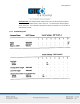
Summagrid IV 2 1.1 Reset Commands 1.1.1 Description The Reset command is used to reinitialize the Summagrid IV system. After receiving a Reset command, the Summagrid IV beeps and sets the communications protocol, report format and other features to match the DIP switch settings. A second command, Change Reset Character, allows the user to change the reset character. 1.1.2 When to Use The tablet is reset every time it is turned on.
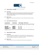
Summagrid IV 3 1.2.2 Command Syntax Change Emulation z(n) Microgrid UIOF MM/SummaSketch CalComp GTCO n=0 n=1 n=2 n=3 1.3 Communication Protocol Commands 1.3.1 Description These commands are used to change the Summagrid IV communication protocols from the host. 1.3.2 When to Use The user needs to change the communication protocols when working with multiple applications that require different information, such as baud rate, parity and number of data bits. 1.3.
Summagrid IV 4 Please note for the tablet to correctly receive this command, the baud rate of the host and tablet must be the same; after receipt of the command at this baud rate, the new baud rate will be put into effect (and subsequent commands from the host must be sent at the new baud rate). 1.3.4 Parity, Data Bits and Stop Bits Parity Parity is an error detection system.
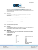
Summagrid IV 5 NOTE: Total number of parity, data and stop bits transmitted at one time cannot exceed ten. 1.4 Communication Protocol Commands 1.4.1 Description Summagrid IV supports two main data formats: ASCII and Binary. Data formats may be selected by DIP switches or by software commands. ASCII Format: The ASCII format sends one byte for each number and character required. Each character is defined by the International ASCII Standard (See Appendix C for the ASCII conversion table.
Summagrid IV 6 Decimal Point: The default ASCII report does not include the decimal point. To include the decimal point, enter d1. To remove the decimal point, enter d0. This command only works when the tablet is in the inches or millimeters format. 1.4.
Summagrid IV 7 1.5 Report Modes: Overview 1.5.1 Description Report modes are used to control the manner and rate by which reports are sent to the host. Different applications have different requirements for accepting data (reports) from the tablet. There are four different report modes: Prompt, Point, Stream and Switch Stream. 1.5.2 When to Use View the individual command descriptions for more detailed information on when to use. 1.5.3 Report Mode Command Syntax 1.6 Report Modes: Prompt 1.6.
Summagrid IV 8 1.6.3 Command Syntax Prompt Mode M3 Prompt Character: Send New Report Prompt Character: Resend Last Report G g 1.7 Report Modes: Point 1.7.1 Description Point mode allows the tablet to send one coordinate pair each time a cursor or stylus button is pressed. 1.7.2 When to Use Point mode is best for mapping or other data collection applications; not recommended for cursor steering applications. 1.7.
Summagrid IV 9 Both Stream and Switch Stream modes may also be used in combination with Increment Mode, an increment filter that prevents duplicate coordinates from being transmitted to the host. 1.8.2 When to Use Stream Mode: Best for applications where speed is important, such as paint programs and handwriting applications. Switch Stream Mode: This mode is best for handwriting applications. 1.8.3 Command Syntax Stream Mode M0 Switch Stream Mode M2 1.9 Report Modes: Set Report Rate 1.9.
Summagrid IV 10 1.10 Report Modes: Increment 1.10.1 Description Increment Mode is an increment filter. Used in combination with Stream or Switch Stream modes, it prevents duplicate reports from being transmitted to the host. When the tablet is in Increment Mode, it sends a report to the host only after the stylus or cursor has traveled a minimum distance, or increment, in the X or Y direction, or if a switch has changed status (been pressed or released).
Summagrid IV 11 1.11.3 Command Syntax 1.12 Transmission Control: Stop and Start 1.12.1 Description The Stop Transmission and Start Transmission commands act as gates, allowing reports to be sent from the Summagrid IV to the host. These commands control data flow, regardless of the report mode. (Stop Transmission and Start Transmission are the equivalents of the transmission protocols XOFF and XON.) 1.12.2 Command Syntax Stop Transmission (XOFF) M0 Start Transmission (XON) M2 1.
Summagrid IV 12 1.13.3 Command Syntax Activate the annunciator for approximately one quarter of a second; emits last tone chosen. Selects one of four different tones for the annunciator and sounds that tone. A Y(n) n=1 low tone n=2 medium tone n=3 high tone n=4 highest tone NOTE: If you want to hear a tone every time a switch is selected, be certain that DIP switch C5 is in the ON position and use the following command: Enable Audible Feedback MT1 Disable Audible Feedback MT0 1.
Summagrid IV 13 1.14.2 How to Relocate Origin To relocate the origin to one of the pre-defined locations, send the appropriate command, listed below under Command Syntax. To change the origin to a specific user-defined location, follow these steps: 1. Send the command F1 to let the tablet know you are redefining the origin. 2. Position the transducer over the desired origin location. 3. Press a button on the transducer to send the new origin location to the system.
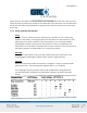
Summagrid IV 14 1.15 Resolution Commands: Fixed Resolution 1.15.1 Description Command enables the user to select the resolution of the Summagrid IV to meet various application needs. The Summagrid IV offers four different fixed resolution settings, in inches or millimeters, which apply to both axes: Inches Millimeters 100 lpi 4 lpmm 200 lpi 10 lpmm 1000 lpi 40 lpmm 2000 lpi 80 lpmm 1.15.
Summagrid IV 15 1.16 Resolution Commands: Variable Resolution 1.16.1 Description The Variable Resolution command is used to define the resolution of each axis independently. It allows the user to set the resolution to any whole number from 0001 to 2540. 1.16.2 When to Use Variable Resolution is used to match the tablet resolution to that of a graphics terminal. The resolution of a graphics terminal is measured in pixels, a unit of measurement similar to counts.
Summagrid IV 16 1.17.4 Example If you have a 36” x 48” tablet and you send the Confirm Resolution command, the following results are sent to the host (in the data format previously selected): Resolution = 1000 lpi 48000, 36000 Resolution = 40 lpmm 48768, 36576 1.18 Skew Correction Command 1.18.1 Description The Skew command is used to align the tablet to a drawing placed upon it by using two points on the drawing as the reference “X-axis”. 1.18.
Summagrid IV 17 Chapter 2 Summagrid IV Output Formats Summagrid IV supports four different output formats: Microgrid UIOF, GTCO, CalComp and Summagraphics MM/SummaSketch. This chapter provides technical information about the Microgrid UIOF output format. 2.1 2.1.1 2.1.2 2.1.3 2.1.
Summagrid IV 18 2.1 Summagraphics Microgrid UIOF Output Format 2.1.1 Overview The Summagrid IV report formats conform to Summagraphics’ Microgrid UIOF (Universal Input/Output Format) standards. To accommodate the special needs, choose the format to be in ASCII or packed binary. 2.1.2 ASCII BCD Report Format Within the ASCII BCD report format the user can choose: The output to be in counts, inches or millimeters.
Summagrid IV 19 Character S X , Y FF Definition Coordinate sign that can be the ASCII + (positive) or the ASCII – (negative) A digit of the X coordinate, where each digit is an ASCII character, 0 through 9 The delimiter character. The default is an ASCII comma A digit of the Y coordinate, where each digit is an ASCII character, 0 through 9 Flag character, identifying the transducer buttons being pressed. The possible combinations are listed in the table below.
Summagrid IV 20 NOTE: The cursors are designed for single, not multiple, button use. Pressing multiple buttons simultaneously yields unpredictable results. T 2.1.3 Tablet area identifier, set to 0 ASCII carriage return ASCII line feed Packed Binary Report Format The packed binary report format is in counts, represented in binary notation. The format is the same for any resolution setting.
Summagrid IV 21 Character LSB MSB PR T PH P SB F X0 to X15 Y0 to Y15 X0 to Y0 X15 to Y15 Sx and Sy Definition Least significant bit Most significant bit Proximity 0 when in proximity and 1 when out-of-prox Tablet area identifier, set to 0 Phasing bit, set for 1 Parity bit One or two stop bits Flag bit, identifying the transducer buttons being pressed. The possible combinations are listed in the table below.
Summagrid IV 22 2.1.
Summagrid IV 23 Chapter 3 Guidelines for Writing a Software Driver If the Summagrid IV is connected to a computer, rather than to a terminal, the computer must have a driver for the tablet. The driver is a software subroutine that collects and decodes Summagrid IV reports for use by another (master) program. This chapter provides some guidelines, in the form of flowcharts, for writing a driver. The flowcharts are for a Summagrid IV using the Summagraphics UIOF packed binary report format.
Summagrid IV 24 3.1 Flowcharts for Writing Drivers 3.1.
Summagrid IV 25 3.1.
Summagrid IV 26 3.1.
Summagrid IV 27 3.1.
Summagrid IV 28 3.1.