Summagrid IV 1 Part 3 provides technical information about Summagrid IV. You’ll find the following appendices in Part 3: Appendix A Appendix B Appendix C Appendix D Appendix E Appendix F Appendix G Appendix H Summagrid IV Interfacing Hardware Summagrid IV DIP Switch Settings ASCII Conversion Chart GTCO Format Emulation CalComp Format Emulation Summagraphics MM/SummaSketch Format Emulation Summagrid IV Specifications Summagrid IV Application Set Up Appendix A Summagrid IV Interfacing Hardware A.1 A.1.1 A.
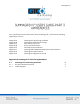
Summagrid IV 2 A.1 Summagrid IV Interfacing Hardware A.1.1 RS-232 Hardware Interface The Summagrid III’s interfacing hardware complies with the EIA (Electronic Industries Association) RS-232C standard. The interface is bidirectional, asynchronous and serial. It is capable of communicating in full duplex and uses the ASCII seven-bit data code. A.1.2 Cable Diagrams Below are cable diagrams for the Summagrid IV cables: PC interface cable and 9-pinto-25 pin AT adapter cable.
Summagrid IV 3 9-pin-to-25-pin AT Adapter Cable
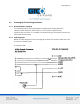
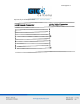
Summagrid IV 4 Appendix B Summagrid IV DIP Switch Settings B.1 B.1 B.2 B.1 Summagrid IV DIP Switch Settings Summagrid IV DIP Switch Table Summagrid IV vs. Microgrid II Switch Settings Summagrid IV DIP Switch Table B.1.
Summagrid IV 5 B.1.
Summagrid IV 6 B.1.
Summagrid IV 7 B.2 Summagrid IV vs. Microgrid II Switch Settings B.2.
Summagrid IV 8 B.2.
Summagrid IV 9 B.2.
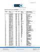
Summagrid IV 10 Appendix C ASCII Conversion Chart
Summagrid IV 11
Summagrid IV 12
Summagrid IV 13 Appendix D GTCO Format Emulation The Summagrid IV can emulate the GTCO output format. This chapter provides the binary and ASCII information for the GTCO output format. D.1 D.1.1 D.1.2 D.1.3 D.1.4 D.1 GTCO Output Format Overview ASCII BCD Report Format Packed Binary Report Format GTCO DIP Switch Settings 13 13 13 17 18 Summagrid IV Interfacing Hardware D.1.1 Overview Summagrid IV report formats conform to GTCO 5A standards.
Summagrid IV 14 Refer to the key for definitions of the format characters. For reports, low resolution is: FXXXXSYYYY For reports, high resolution is: FXXXXXSYYYYY Character S Definition Space (optional) X A digit of the X coordinate, where each digit is an ASCII character, 0 through 9 , The delimiter character.
Summagrid IV 15 NOTE: The cursors are designed for single, not multiple button use. Pressing multiple buttons simultaneously yields unpredictable results. ASCII carriage return ASCII line feed Character LSB MSB PH SB PB1-PB5 Definition Least significant bit Most significant bit Phasing bit, set for 1 One or two stop bits Flag bit, identifying the transducer buttons being pressed. The possible combinations are listed in the tables below.
Summagrid IV 16 Flag Bit Definitions for 16-Button Cursor Flag Bit Definitions for Two-Button Stylus and Four-Button Cursor
Summagrid IV 17 D.1.3 RS-232 Hardware Interface The Summagrid IV can emulate two kinds of GTCO binary formats: low and high resolution.
Summagrid IV 18 D.1.
Summagrid IV 19 Appendix E CalComp Format Emulation The Summagrid IV can emulate the CalComp 9100 output format. This chapter provides the binary and ASCII information for the CalComp output format. E.1 E.1.1 E.1.2 E.1.3 E.1.4 GTCO Output Format Overview ASCII BCD Report Format Packed Binary Report Format CalComp DIP Switch Settings 19 19 19 23 25 E.1 CalComp Output Format E.1.1 Overview Summagrid IV report formats conform to CalComp 9100 standards.
Summagrid IV 20 Refer to the key for definitions of the format characters. Format 1 (1000 LPI, 40 LPMM) XXXXXYYYYY 1016 lpi XXXXXXYYYYYY FORMAT 2 (1000 LPI, 40 LPMM) XXXXX, YYYYY, 1016 lpi XXXXXX, YYYYYY, FORMAT 3 (1000 LPI, 40 LPMM) XXXXXYYYYY 1016 lpi FORMAT 4 1000 LPI XX.XXX, YY.YYY, 40 LPMM XXXXX., YYYYY.
Summagrid IV 21 Character T Definition Tablet status character M Mode status character R = Run U = Line T = Track I = Increment P = Point P Pen (cursor) status X A digit of the X coordinate, where each digit is an ASCII character, 0 through 9 , Delimiter character. The default is an ASCII comma. Y A digit of the Y coordinate, where each digit is an ASCII comma. C Cursor flag character, identifying the transducer buttons being pressed. The possible combinations are listed in the table below.
Summagrid IV 22 NOTE: Cursors are designed for single, not multiple, button use. Pressing multiple buttons simultaneously yields unpredictable results.
Summagrid IV 23 E.1.3 Packed Binary Report Format The Summagrid IV can emulate two types of CalComp binary formats: low and high resolution.
Summagrid IV 24 Character LSB MSB P C0-C4 Definition Least significant bit Most significant bit Parity bit Flag bit, identifying the transducer buttons being pressed. The Possible combinations are listed in the tables below.
Summagrid IV 25 Flag Bit Definitions for the Two-Button Stylus and Four-Button Cursor E.1.
Summagrid IV 26 Appendix F MM/SummaSketch Format Emulation The Summagrid IV can emulate the Summagraphics MM/SummaSketch output format. This chapter provides the binary and ASCII information for the MM/SummaSketch output format. F.1 F.1.1 F.1.2 F.1.3 F.1.4 F.1.5 MM/SummaSketch Output Format Overview Binary Report Format ASCII BCD Report Format MM/SummaSketch Command Summary MM/SummaSketch Switch Settings 26 26 27 27 30 31 F.1 MM/SummaSketch Output Format F.1.
Summagrid IV 27 F.1.2 Binary Report Format Binary Format for Absolute Coordinates Binary Format for Relative Coordinates F.1.
Summagrid IV 28 Character X Definition X coordinate digit, where each digit is an ASCII character from 0 to 9. , ASCII comma Y Y coordinate digit, where each digit is an ASCII character from 0 to 9. F Stylus and cursor flag character, identifying the button status Flag Bit Definitions for the Stylus and Four-Button Cursor Character LSB MSB Fa-Fc Definition Least significant bit Most significant bit Flag bit, identifying the stylus/cursor buttons being pressed.
Summagrid IV 29 Flag Bit Definitions for the Stylus and Four-Button Cursor Sx and Sy X and Y coordinate signs. 1 is positive and 0 is negative. In absolute coordinates, the sign is always positive. In relative coordinates, the sign can be positive or negative. T Tablet identifier. Choice of 1 or 0 and command is controlled. PR Proximity bit. 0 is in-prox and 1 is out-of-prox. PH X0, X1… Phasing bit, which is always 1. X coordinate bits Y0, Y1…. Y coordinate bits.
Summagrid IV 30 F.1.
Summagrid IV 31 F.1.5 MM/SummaSketch DIP Switch Settings When configuring Summagrid IV in the MM/SummaSketch format, the DIP switches perform the same functions except in the following situation: When the tablet is placed in MM binary format, it defaults to 8 data bits, regardless of how DIP switch A-7 (switch bank A, position 7) is set.
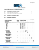
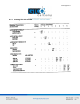
Summagrid IV 32 Appendix G Summagrid IV Specifications Physical Specifications Tablet Size 51.35” x 68.28”, 44.5” x 56”, 32.5” x 44.5”, 26.60” x 32.63” Active Area 44” x 60”, 36” x 48”, 24” x 36”, 18” x 24” Un-Boxed Weight (Tablet & Controller) 80 lbs. (44” x 60”), 55 lbs. (36” x 48”), 30 lbs. (24” x 36”), 20 lbs. (18” x 24”) Boxed Weight (Shipping Weight) 100 lbs. (44” x 60”), 80 lbs. (36” x 48”), 50 lbs. (24” x 36”), 33 lbs.
Summagrid IV 33 Environmental Specifications Operating Environment +45 degrees to +100 degrees Fahrenheit +7 degrees to +43 degrees Celsius 8% to 90% relative humidity, non-condensing Non-Operating -45 degrees to +145 degrees Fahrenheit -43 degrees to +63 degrees Celsius 8% to 90% relative humidity, non-condensing
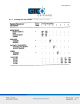
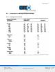
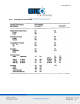
Summagrid IV 34 Appendix H Summagrid IV Application Set Up This appendix provides DIP switch settings for the popular software applications. The switch settings listed are for the 36 x 48 tablet only. Use this chart as a quick reference; for more detailed information please refer to the tablet installation procedures in the application’s manual. NOTE: Information provided was supplied by the software manufacturers and may not have been tested by Summagraphics.
Summagrid IV 35
Summagrid IV 36
Summagrid IV 37