
Installation Instructions
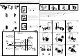

Ⅰ:Package Contents
INSTRUCTION FOR ELECTRONIC DOOR LOCK
(Applicable Model:E030fingerprint)
FOLD HERE ON
DOOR EDGE
1
2
MARK FOR
1
3
4
"(45mm)
DOOR
MARK FOR
1
3
8
"(35mm)
DOOR
THEN DRILL 1"(25mm)HOLE
IN CENTER OF DOOR EDGE
(2"IN DEPTH
3
TEMPLATE
FOR INSTALLING ENTRY
LOCK AND DEADBOLTS
2
3
8
"(60mm)BACKSET
2
3
4
"(70mm)BACKSET
IMPORTANT !
PLACE TEMPLATE
ON HIGH EDGE OF
DOOR BEVEL
MARK CENTER OF
HOLE ON DOOR FACE
DRILL 2
1
8
"
(54mm) HOLE
4
5
Keypad
Base plate
3
4
(19mm) Screws-4ea.
19
16
(30mm)Screw-2ea.
Ⅱ:Installation and commissioning
a
b
c
d
3,Installation step
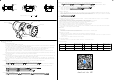
To install the Back Plate
To install the Battery Box
To install the Back Cover
When installing the back cover, pay attention to the
downward direction of the screw hole. This screw is an
anti-tooth screw, which is turned clockwise to tighten
the screw.
Set switch
Restore factory settings
Screw Hole up
Screw Hole Down
3
4
(19mm) Screws-2ea.
19
16
(30mm)Screw-2ea.
1
2
3
4
5
6
7
8 9
a
b
c
Do not tighten the screws at once, when there is a bit
of loosening, turn the front and rear handles left and
right for many times, then tighten the screws again.
Latch
Strike plate Plastic box
Hex key
Install the latch (Be
note the direction)
Install the keypad
1,Punching in the door according to the dimension requirement.
a,Backset is distance from door
edge to centre of hole on door
face,adjust Latch fit both backset
of 2
3
4
(70mm) or 2
3
8
(60mm)
c,Use the marks as a guide to drill a
hole
∅
2
1
8
(54mm) through the door face
for the lockset, then a hole of
∅
1
(25.4mm) for Latch.
b,Select the height and
backset as desired on the door
face,use the Template as an
indication to mark the centre
of the circle on the door face
and the centre of the door
edge.
2,Install Strike
Close door and mark horizontal centre of Latch on to door frame.Mark vertical line where door edge meets
frame and measure in half of door thickness to find vertical cetre.
Extend both lines until they intersect and drill a 1 (25.4mm)hole to
1
2
(15mm) depth.
Position Strike plate and mark around edge.
Chisel fram to approx
1
16
(1.6mm) depth or until Strike sits flush.
Using two wood screws fix Strike to the frame.
USB emergency external power supply
When the door lock is powered on, press the switch with a small
needle through the circular hole for 5 seconds, and the system
will return to the factory status
When the door lock voltage is too low
,connect the USB port with the
charger for temporary power supply
Note !Screw Hole Down
This manual is applicable to multiple models , The physical appearance may not be in accordance with the manual, but the operation is the same , it will not affect use