
User's Manual

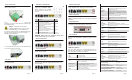

Video is not active.
Video is active
VIDEO
No MoCA link active
MoCA link active
MoCA
MoCA Connection
Page 2
4 egaP3 egaP
Page 5
Fiber Connection
1.) On the back left side of the unit is fiber cover.
Slide it off as shown.
2.) With the fiber connector exposed, remove the
dust plug, clean the fiber ends and terminate the
SC equipped fiber.
Danger! .
Exposure to invisible
LASER radiation may cause serious
retinal damage or even blindness.
Verify the optical source is disabled through
the use of an optical power meter before
handling optical fibers.
3.) Insert the fiber into the cover slot and slide the
cover back onto the 72xx unit.
DC Power Input
1.) Connect the 2.1mm DC power plug to the
port labeled PWR.
UPS Power and Alarms
1.) The UPS power/alarm
input uses a MOLEX 43025-
0800 connector. Pin orienta-
tion as shown is viewed from
the rear.
Pins for the connector are Molex 46235-5002
NOTICE:
Please adopt
UL
certificated
UPS
which
meets Limited Power Source standard.
POTS Connections
1.) Connect up to 2 phones to the ports labeled POTS1
and POTS2.
LAN Connections
1.) Connect the computers/routers to the ports labeled
ETH1 through ETH2.
CATV Connection
1.) Connect the television to the port labeled Coax
Network. This port also supports Return Service on
PIN NAME ALM
1 Power Input (+12 VDC) –
2 UPS Status: On Battery 1
3 UPS Status: Battery Missing 2
4 Signal Return –
5 Power 12V Return –
6 UPS Status: Replace Bettery 3
7 UPS Status: Low Battery 4
8 No Connection (N/A) –
WiFi Connection
1.) Change the notebook/computer WiFi network
SSID to “iphotonix-ONTxxxx”. This may be changed
manually.
USB Connection
1.) Connect the flash-disk/portable hard disk to the
port labeled USB on the left side of the units.
User Controls
1.) The 72xx SFU ONT is equipped with an ON/OFF
button. User functionality should be limited to this
button.
LED Descriptions
The 72xx SFU ONT has visual LED indicators to
help the user determine the operational state of the
unit. The LEDs are defined as follows:
Power
Battery
MGMT
ON Unit is powered on
OFF Unit is powered off
ON Battery is charged and unit is operating nor-
mally on external power.
Flashing Slow Unit is running off of battery power only.
Check power supply to unit.
Flashing Fast Battery is low and unit may turn off if exter-
nal power is not restored.
OFF Battery is missing or defective.
ON Management channel (OMCI) is active
OFF Management channel (OMCI) is not active.
ETH 1- 2
POTS
FAIL
WLAN
Environmental Requirements
ON Ethernet link is operational.
Flashing Indicates data transmission / reception.
OFF No Ethernet link or port is not equipped.
ON Line is off hook (call active or in process)
Flashing Slow Indicates ringing line.
OFF Line is on hook (no call in process) or
port is not equipped.
ON Indicates Loss Of Signal (LOS). No opti-
cal signal is present.
Flashing
Slow
Marginal signal indicates a weak optical
signal from carrier. Clean fiber connection
per local practice and check power with an
optical meter.
Flashing Fast Software upgrade has failed.
OFF Optical signal is present and operating nor-
mally.
ON WiFi function is active (+2– -6 range)
Flashing Indicates active data TX/RX
OFF WiFi function is not active
Rated Voltage: DC 12V
Rated Current: 2A
Operating Temperature: +5°C to +40°C
Operating Relative Humidity: 5% to 85%
Storage Temperature: -40°C to +60°C
Storage Relative Humidity: 0% to 95%
select models.
1.) Connect the coaxial cable to the port labled
Coax Network, the same port with CATV.
ON
OFF
Flashing Indicates data transmission / reception.
ON
OFF