
User's Manual


3.5 Stick calibration
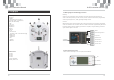
3.6 Trainer port (Digital Signal Converter, DSC)
This port is used to connect the transmitter to an
optional simulator on your computer. The trainer
cable and USB adaptor is sold seperately.
Instructions:
Attention:
1.Do not plug unauthorized devices into the DSC port
on the transmitter; doing so will void the warranty.
2.This device is compatible with R/C simulators only.
After simulator installation, plug the trainer cable into the
DSC port and the USB adaptor; then plug the USB adaptor
into the USB port on your computer.
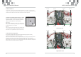
3.7 Throttle stick configuration
To switch the throttle stick from the left column to the right (or vice versa),
a mechanical modification needs to be made:
Remove the 4 screws and rear cover to expose the base plate. The photo below shows the in
ternal below shows the internal views of right and left throttle setups.Using a phillips
screwdriver loosen and remove Screw A to adjust the throttle mode,then screw the Screw A.
Potentiometer cable connection in the corresponding positions are shown below. Replace the
rear cover when the mechanical switch is completed.
Left throttle stick
1
2
3
4
Right throttle stick
Center both control columns,simultaneously hold the “throttle” trim up and the
“rudder” trim left (mode 2); turn the transmitter on. The buzzer will sound four times,
release all trims and reduce the throttle column to its lowest position.
1
2
3
4
1
2
3
4
1
2
3
4
1
Screw A
H-6Q Instruction Manual H-6Q Instruction Manual
Screw A Screw A Screw A
Screw A Screw A Screw A Screw A
Screw A Screw A Screw A Screw A
Screw A Screw A Screw A Screw A
6
7