Product user manual Pulmonary Function Tester Model: A9 PLEASE READ ALL THE INFORMATION IN THE PACKAGE INSERT BEFORE USING THE PULMONARY FUNCTION TESTER. IF YOU DO NOT UNDERSTAND THE INSTRUCTIONS, CONSULT HOMESUN, CALL 400-030-1510 (Working Time: from Monday to Friday, Beijing time 9:00-18:00), OR WRITE TO service@huxijia.cn. Guangzhou Homesun Medical Technology Co.
Foreword This product manual contains important content that must be understood for the safe and correct use of this product, and is a part of this product. Therefore, during the entire service life of this product, the instruction manual must be placed at the operating location of the equipment at any time for reference. This product must be operated by personnel who have received relevant training and have relevant knowledge and experience.
Content 1. Product description ........................................................................................................... 1 1.1 Product brief description ............................................................................................. 1 1.2 Intended use / indications for use................................................................................ 1 1.3 Requirements for patients ...........................................................................................
11.2 Security software..................................................................................................... 18 11.3 Data and equipment interface ................................................................................. 18 11.4 User access control mechanism .............................................................................. 18 12. Electromagnetic compatibility instructions .................................................................. 19 12.1 Parameter description......
1. Product description 1.1 Product brief description Product name: Pulmonary Function Tester Model: A9 Embedded software release version: V1 Mobile software release version: V1 Computer software release version: V1 1.2 Intended use / indications for use Pulmonary Function Tester is intended to be used for measurement and data collection of lung function parameters. The system performs cooperation-dependent flow volume measurements. Mostly it will be used for COPD and Asthma patients.
Figure 1 Product structure composition 1.5 Product performance 1.5.1 Measuring the amount of principle introduction The device uses a flow sensor to measure the gas flow and volume of the patient's exhaled or inhaled gas. According to the volume-time curve and the flow-volume curve, the pulmonary ventilation indicators of human respiratory physiology are analyzed, such as slow vital capacity, maximum minute ventilation and forced vital capacity and other parameters.
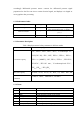
accordingly. Differential pressure sensor: converts the differential pressure signal proportional to the flow rate into a certain electrical signal, and displays it in digital or curve graphics after processing. 1.5.2 Performance index Measurement parameters Range Maximum indication error Expiration /inspiration flow ( 0-16 ) L/s ±5% or ±0.17L/s , whichever is greater Airflow resistance / Volume ( 0-10 ) L Flow measurement range < 0.15 kPa / ( L/s ) ±3% or ±0.05L , whichever is greater 1.5.
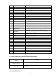
1-8 1-9 FIV1 PEF forced inspiratory volume in one second peak expiratory flow 1-10 FEF25% forced expired flow at 25% of FVC 1-11 1-12 1-13 FEF50% FEF75% FEF25%-75%(MMEF) forced expired flow at 50% of FVC forced expired flow at 75% of FVC forced expiratory flow from 25 % -75 % of FVC 1-14 1-15 PIF FIF50% peak inspiratory flow forced inspiratory flow at 50% of FIVC 1-16 FET100% forced expiratory time to reach 100% of FVC 1-17 FEV1/FVC forced expiratory volume in one second to FVC ratio 1-18
1.6.1 Absolute contraindications 1) Suffered from myocardial infarction, stroke, and shock in the past 3 months; 2) Severe cardiac insufficiency, severe arrhythmia, and unstable angina in the past 4 weeks; 3) Large hemoptysis in the past 4 weeks; 4) Seizures need treatment; 5) Uncontrolled hypertension (systolic blood pressure > 200mmHg, diastolic blood pressure > 100mmHg); 6) Aortic aneurysm; 7) Severe hyperthyroidism. 1.6.
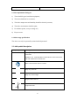
Warranty card ×1 1.8 Site requirements during use 1) There should be good ventilation equipment; 2) The venue should not be too narrow; 3) The indoor temperature and humidity should be relatively constant; 4) The indoor environment should be quiet; 5) If conditions permit, set up a waiting area; 6) Easy to rescue. 1.9 Other usage specifications The device can only be operated by trained medical personnel. 2. Label symbol description Graphics Symbols Meaning Prescription only. CAUTION: FEDERAL U.S.
Humidity limitation Atmospheric pressure limitation Stacking limit by 5 Type BF applied part Low-frequency electromagnetic radiation “WEEE (Waste Electrical and Electronic Equipment)”. The waste products should be handled legally. Caution Serial number Manufacturer Class II equipment Recyclable Unique device identifier 3.
Please clean and disinfect the pressure taking structure according to the method specified in the product manual. Please connect the device to the designated device, otherwise the device will be unusable or the measurement data will be wrong. Please test according to the method specified in the product manual, and confirm that the current measurement mode and the blowing method are correctly matched, otherwise the measurement results will be inaccurate.
explained by professional medical personnel. A qualified physician must reassess all measurements. An interpretation by the medical device is significant only when considered together with other clinical findings. When using the device, pay special attention to the user manual where this symbol is marked. 4. Installation and use instructions 4.1 Check the equipment list Check whether the product and its accessories are complete according to the product list in 1.7.
Before using the equipment every day, a standard calibration and verification are required. In addition, a 3- flow calibration and verification is performed once a week. For specific methods, please refer to the calibration method in the corresponding software instructions. 4.3.2 Test mode selection Press the left or right button on the device to select the test mode, and press the middle button to enter the corresponding test mode. 4.3.
doctor, and master the essentials of FVC movements. Avoid fatigue of subjects and achieve satisfactory results. 2) Connect the mouthpiece to the mouth, wrap the mouthpiece tightly with your lips, and clamp the nose clip to ensure that the nose and mouth do not leak. If some subjects cannot guarantee that the corners of the mouth will not leak, a special mouthpiece with a tooth mask can be added. 3) Breathe calmly for 4-5 times.
When the device is turned on, long press the shutdown button, the instrument display screen displays the shutdown interface, and the device emits a "shutdown in progress" prompt sound. After the above actions are completed, the device shutdown is complete. 4.6 Charging Plug one end of the data cable into the USB port of the computer to charge the device. When charging, a dynamic battery charging indicator icon will appear on the display.
Disposable pulmonary function meter filter Discarded immediately after use in each patient Special reminder: Disposable products must be discarded. The following parts must be cleaned and disinfected once a day, see the following table: The screen is cleaned and The air head of the flow sensor is disinfected once a day cleaned and disinfected once a day Caution: Thorough disinfection of all contaminated parts can avoid potential risks of infection.
about 15 minutes, and add 0.3% sodium bicarbonate to enhance its sterilization and disinfection effect. ③ After disinfection, rinse all parts with a large amount of distilled water and place them in a clean place to dry thoroughly. It is recommended that all patients be cleaned and disinfected after the test on the same day, so that they can be dried naturally and used next time.
service. 2) The maintenance of this equipment is limited to qualified personnel designated by the manufacturer. Users should not repair the equipment by themselves. 3) When the device prompts that the battery is low, use a power source that meets the USB specification to charge in time. If the battery is found to be used for too short a time, you should stop using the device and contact after-sales customer service.
2) Avoid direct sunlight; 3) Avoid getting wet from the rain; 4) Handle with care during the moving process. 9. Failure analysis and resolution Failure phenomenon Cause Analysis Low battery Can not boot Possible equipment damage Solution Please connect the charger to charge. Please contact the after-sales customer service center. The Bluetooth function of the Please turn on the Bluetooth mobile phone is not turned on function of the mobile phone.
10. Product quality information 10.1 Warranty service From the date of purchase, the product enjoys a free warranty within one year with the purchase invoice, but does not include the following failures caused by the user's personal reasons.
The manufacturer has the right to return the contaminated product to the shipper 10.3 Production date and expiry date Product production date: see product label Product expiration date: three years 11. Cybersecurity instructions The device has the function of data transmission to mobile terminal software and computer terminal software. 11.
data Equipment maintenance personnel independently by themselves, the company needs to assign them separately Access device data, perform software update and maintenance password must have English capitalization and numbers, and the length should not be less than 6 digits. The account name matches the password. The password must Pass account password have English capitalization and numbers, and the length should not be less than 6 digits. 12. Electromagnetic compatibility instructions 12.
the manufacturer of Model A9 could result in increased electromagnetic emissions or decreased electromagnetic immunity of this equipment and result in improper operation. 3) Use of Model A9 adjacent to or stacked with other equipment should be avoided because it could result in improper operation. If such use is necessary, this equipment and the other equipment should be observed to verify that they are operating normally. 12.3 FCC declaration This device complies with Part 15 of the FCC Rules.
12.4 Declaration of conformity Table 1 Guidance and manufacturerś declaration – electromagnetic emission The Pulmonary Function Tester(A9)is intended for use in the electromagnetic environment specified below. The customer or the user of Pulmonary Function Tester(A9)should assure that it is used in such an environment. Emissions test RF emissions Compliance Electromagnetic environment - guidance Group 1 The Pulmonary Function Tester(A9)uses RF energy only for its internal function.
30 %.
IEC 61000-4-6 150 kHz to 80 MHz 150 kHz to 80 MHz Recommended separation distance 6 V in ISM and amateur radio bands between 0,15 MHz and 80 MHz ] P 6 V in ISM and d [ V1 amateur radio bands between 0,15 12 MHz and 80 MHz Radiated RF 3 V/m 3 V/m IEC 61000-4-3 80 MHz to 2.7 GHz 80 MHz to 2.7 GHz 385MHz-5785MHz Test specifications for ENCLOSURE PORT IMMUNITY to RF wireless communication equipment (Refer to table 9 of IEC 60601-1-2:2014) 3.
Table 4 Recommended separation distances between portable and mobile RF communications equipment and the Pulmonary Function Tester(A9) The Pulmonary Function Tester(A9)is intended for use in an electromagnetic environment in which radiated RF disturbances are controlled.
25
Annex 1 Product user manual Pulmonary function tester mobile software Model: A9 Guangzhou Homesun Medical Technology Co.
Illustrate Thank you for purchasing Homesun products. Before using the product, please read the contents of this manual carefully so that you can use it correctly. Keep this instruction manual properly after reading so that it can be consulted whenever you need it. Product name: Pulmonary function tester mobile terminal software user manual Software release version: V1 Manufacturer name: Guangzhou Homesun Medical Technology Co.
responsible for the safety, reliability and performance of the product.which is: The assembly operation, expansion, re-adjustment, improvement and maintenance are all carried out by professionals approved by Homesun; The product operation is carried out in accordance with this instruction manual. Warranty and repair service The warranty period of the purchased product is subject to the sales contract.
If you do not pay or delay payment for the paid repair service, Homesun Company will suspend the repair service until you pay. After-sales service unit Unit name: Guangzhou Homesun Medical Technology Co., Ltd Address: Floor 7th, TianxiangBusiness Building, No.28, Li Fu Road, Haizhu District, Guangzhou,GD .
Content Chapter 1 Manual overview .................................................................................................. 1 1.1 Overview ..................................................................................................................... 1 1.2 Scope of application of the manual ............................................................................. 1 1.3 Guide to the manual ....................................................................................................
7.2 Routine maintenance method .................................................................................... 48 7.3 Daily use precautions ................................................................................................ 48 7.4 Quality control .......................................................................................................... 48 Chapter 8 Failure analysis and treatment ............................................................................ 49 8.1 Overview ...
Chapter 1 Manual overview 1.1 Overview This chapter describes how to use the software instruction manual, which is randomly included, and provides a detailed description of the purpose, function, and operation of the software. Before you use the software, read, and understand it carefully to ensure that the software is used correctly, performs at its best, and ensures the safety of the operator. In the daily use of this software, please strictly follow the instructions in the manual. 1.
Understand the software installation method, installation steps and the correctness of the software Use tutorial Input data, calculation and other settings, sample result report generation Understand the maintenance and precautions of the software Understand the handling methods and steps of software failures Chapter 5 Software installation and uninstallation Chapter 6 Software interface and operation Chapter 7 Maintenance and precautions Chapter 8 Failure analysis and treatment Understand software ele
1.6.1 Causes a system failure or termination condition: There may be a software failure: When there is an error input caused by the user's carelessness or the software itself has an error, the software can recover by itself without an infinite loop. 1.6.
Chapter 2 Software description 2.1 Operating environment 1) Hardware standard configuration requirements: Memory: 2GB RAM or above; Storage hard disk space: 16GB or above; 2) Software standard configuration requirements Operating system: Android 7.0 or above; Precautions, warnings, and prompt content. The software is a clinical examination software used for screening.
2.2.3 Maximum concurrent number The maximum number of concurrent users of this software is 1. 2.2.4 Data interface Use the USB/Bluetooth interface to transmit to the mobile terminal platform where the software is located. 2.2.5 Specific hardware A9 2.2.6 Clinical function 1) Forced vital capacity The forced vital capacity test program includes: flow-volume curve display, volume-time curve display, end-tidal flow guidance, and forced vital capacity display parameters.
Patients create, edit, query, delete, view patient file details, and view patient history test records. 7) Data management Report query and data search.
log recording program; Software should have maintenance contact information in the "About" information. 2.2.13 Quality requirements Shall comply with Chapter 5 (except 5.3.9 ~ 5.3.13) of ISO / IEC 25051: 2014 Software engineering - Systems and Software Quality Requirements and Evaluation (SQuaRE) – Requirements for quality of Ready to Use Software Products (RUSP) and instructions for testing.
Chapter 3 Working principle and scope of application 3.1 Working principle This software is suitable for data detection based on the pulmonary function tester produced by our company. The software supports 4 different types of pulmonary function tests: FVC, SVC , MVV and bronchial diastolic test. The software works as follows: 1. through the USB / Bluetooth acquired detection of human pulmonary function tests, and increasing the number of data curve data; 2. Read and calculate curve data.
Chapter 4 Major component structure The product consists of login, homepage, forced vital capacity, slow vital capacity, maximum minute ventilation, bronchial diastolic test, calibration, patient management, data management, and system setting modules.
Chapter 5 Software installation and uninstallation 5.1 Overview This application software is dedicated software, and there are full-time after-sales personnel to guide the installation. Please notify Homesun or the local agent after receiving the pulmonary function tester product. 5.2 Installation requirements Before installation and use, be sure to read the instruction manual carefully, and the operator must be familiar with the use and operation methods to ensure that the software can work normally. 5.
Figure 1 Installation interface b) Wait for the software to automatically complete the installation, and generate a software startup shortcut icon on the desktop. Figure 2 Desktop icon interface c) Click the software startup icon to use it. 5.4 Software uninstallation procedures 1) Open the settings of the Android system, select the application, and select the AX program. 2) The uninstall dialog box pops up, select uninstall to complete the deletion.
Figure 3 Uninstall interface 12
5.
Chapter 6 Software interface and operation 6.1 User login As shown in the figure below, after the software is started, the user login dialog box is automatically displayed. After entering the user name and password, click [Login], and you can enter the main interface after logging in successfully. The initial user account of the software can be obtained from Homesun after-sales personnel.
Figure 5 main interface 1) FVC mode. Click the FVC button to perform FVC detection. 2) SVC mode. Click the SVC button to perform SVC detection. 3) MVV mode. Click the MVV button to perform MVV detection. 4) Bronchial Diastolic Test. Click the POST Bd button to perform a pulmonary function test before and after diastolic medication. 5) Calibration. Click the "Calibration" button to calibrate the device. 6) Patient management. Click "Patient management" to see a list of historical patients.
6.3.2 Standard calibration 1) The 3L calibration pump and pulmonary function testing instrument are connected, select in the software "3L", click the upper right corner of the "standard" button, click "Start" button, enter the standard monitor calibration measurement page.
6.3.
Figure 7 3 flow verification interface 6.4 Forced vital capacity test procedure 6.4.1 Forced vital capacity test Select the forced vital capacity test (FVC) to prepare to start the test.
6.4.1.1 Description of function homepage 1) Test items - FVC, FEV1, FEV1% FVC, PEF, FEF25, FEF50, FEF75, MMEF and so on were used as the measured indexes of FVC.
6.4.1.2 Description of operating real-time measurement homepage Figure 10 FVC measurement real-time interface 1) Real-time dynamic display of flow rate - volume curve during breathing . 2) Real-time dynamic display of tidal volume and respiratory rate during steady breathing, guiding the user to measure the steady control progress value within the green range.
cannot guarantee that the corners of the mouth will not leak, a special mouthpiece with lip and tooth cover can be added. Caution: The user purchases a detachable mouthpiece and a disposable pulmonary function meter filter, which must be a legally marketed product registered by the FDA. Mouthpiece specifications: inner diameter 30mm, outer diameter 32-34mm, height 50mm-120mm. Specification of disposable pulmonary function meter filter: inner diameter 1=30mm. 3) Breathe calmly for 4-5 times.
6) When completion of the blow 3 times after the actual measurement, the system automatically obtains the repeatable quality level according to the quality control standard, if there is a low-quality measurement record that is unacceptable for a single operation, you can click to select the actual measurement record to delete it. 7) Click "Generate Report" to generate the report and enter the report preview page.
Figure12 FVC report interface 23
6.5 Maximum minute ventilation test procedure Select the maximum minute ventilation test (MVV) to prepare to start the test.
Figure 14 MVV measurement results interface 6.5.1 Operation steps 1) Subject takes a standing or sitting position, clamps the nose clip, and connects the mouthpiece to the device, and breathes calmly for 4 to 5 times. After the exhalation is stable, continue to breathe for 12 or 15 seconds at the maximum breathing amplitude and maximum speed. Caution: The user purchases a nose clip, which must be a legally marketed product registered by the FDA.
3) Each time the patient completes a set of measured values, the monitoring page will prompt whether the measured results are acceptable. Such as ticking is acceptable, you can click "end" to end this test and save the data. Such as the cross is an unacceptable result and the reason is prompted, you can click "New Test" to start a test.
Figure16 MVV report interface 27
6.6 Slow vital capacity test procedure Choose slow vital capacity test (SVC) to start the test. Figure 17 Measurement mode selection interface 6.6.
Figure 18 SVC measurement result interface 6.6.2 Operation steps 1) Connect the mouthpiece to the mouth, wrap the mouthpiece tightly with your lips, and clamp the nose clip to ensure that the mouth and nose do not leak. If some patients cannot guarantee that the corners of the mouth will not leak air, a special mouthpiece with lip and tooth cover can be added.
the breathing is stable, inhale as much as possible at the end of the expiration at a moderate speed (total lung volume), and then exhale to the end completely. Caution: The user purchases a nose clip, which must be a legally marketed product registered by the FDA. 3) Repeat the above steps to check more than 3-5 times, and rest for more than 1 minute between 2 times.
6.6.
Figure20 SVC report interface 32
6.7 Bronchial diastolic test procedure Select the POST Bd on the homepage and prepare to start the test. For the specific test, refer to the forced vital capacity test procedure. The diastolic test requires a forced vital capacity test before and after the medication. After completion, a bronchodilation report can be generated.
Figure21 POST Bd report interface 34
6.8 Data management 6.8.1 Patient management Figure 21 Patient management interface Click the new patient button to add patients; Click the patient record in the patient list to enter the patient details page, where you can view the patient's detailed information and measurement record. At the same time, edit and delete the patient information. Figure 22 Patient information view interface 6.8.
Figure 23 New patient interface① Id card reading:Click the "ID card reader" button, place the ID card correctly, read the information successfully, automatically fill the information obtained by the card reader into the create patient popup, click the "Next" button to complete the patient creation New test:After filling in the patient information, click "Next" button to enter the measurement page.
Figure 24 New Patient Interface② After filling in the new patient information, click the "New test" button to return to the patient management page, and the new patient information appears on the patient management page. 6.8.3 Edit patients Select any patient information in the patient list on the patient management page to enter the patient details page. Click the "Edit" button to enter the patient editing page.
Figure 25 Patient information Interface Enter the patient editing page: Figure 26 Patient edit Interface Clicking Save will display the created test patient information.
6.8.3 Delete patient Click "Delete", it will prompt whether to delete patient information.
6.9 Report management On this page, you can view generated reports. Click upload report to synchronize the unuploaded reports to the computer software. The computer software can view and browse the report. Figure 28 Report management interface 6.10 System settings System settings are divided into system settings and pulmonary function settings. 1) System settings include account management, hospital Setting, server address, sound/brightness, and updates.
Figure 29 Account manage interface ②Hospital Setting Edit: Edits hospital information Add hospital: Add hospital information. Note: The new hospital information will replace the original hospital information.
Figure 30 Hospital setting interface① Select departments, doctors, operators and other options to display the information of departments, doctors, and operators of the current hospital, and add, modify, and delete them. Figure 31 Hospital setting interface② ③Server address It is used to manage server addresses. If you select the server address below the URL, the server address will be automatically added to the URL. Click “Save”.
Figure 32 Server Address interface ④Sound/Brightness Adjust sound/brightness Figure 33 Sound/Brightness interface 43
⑤Update The software upgrade module is to check the version. If the testing software is upgraded, contact your local agent. Figure 34 Update interface 2)The pulmonary function settings include report setting, medicine setting, parameter setting and question setting. ①Report setting Predicted source: Select a mode from the drop-down list box to switch the expected value mode. Report subtitle: Click the edit button at the bottom right of the subtitle bar to enter the edit box and edit the report subtitle.
Figure 35 Report setting interface ②Medicine setting Drug search: click the search button to search for drugs according to the drug category and drug name in the drop-down box Add medicine: click "New" button to enter the popup window of add medicine for adding the medicine Drug information editing: Click the edit button in the drug list to modify the drug information Delete drug: Click the delete button in the drug list to delete the drug.
Figure 36 Medicine setting interface ③Parameter setting. Report setting: Click the drop-down box to switch measurement mode, mode switch, and the parameter list below follows the switch. Parameter list operation: display and hide parameters when changing measurement mode.
Figure37 Parameter setting interface ④Questionnaire setting Select the type of the poll to control the type of the new poll displayed or hidden.
Chapter 7 Maintenance and precautions 7.1 Overview In order to give full play to the performance of this software, ensure its reliability, and prolong its service life, please maintain, and maintain it strictly in accordance with the requirements of this chapter. 7.2 Routine maintenance method Such as occurs when the software failed to start, run-time error, etc., should stop using, and contact Guangzhou Homesun Medical Technology Co., Ltd., or local agents. 7.
Chapter 8 Failure analysis and treatment 8.1 Overview This chapter introduces the handling methods and steps of common software failures. If you still cannot eliminate the failure according to the work instructions in this chapter or need more and more detailed information, please contact Homesun 's after-sales service department. This manual is not equivalent to the maintenance manual. It only provides the measures that the operator should take when the analyzer has a fault alarm. 8.
Chapter 9 Electromagnetic compatibility statement 9.1 Parameter description Name Working frequency Modulation type Maximum Tune-up power(dBm) Bluetooth 2.4GHZISM BAND GFSK -3.00 Name Cable length ( m ) Whether to block Remark USB Cable 2.0 Yes / Even if other equipment meets the emission requirements of the corresponding national standards, the equipment or system may still be interfered by other equipment. 9.
9.3 FCC declaration This device complies with Part 15 of the FCC Rules. Operation is subject to the following two conditions: ⑴ This device may not cause harmful interference, and ⑵ This device must accept any interference received, including interference that may cause undesired operation. Note: This equipment has been tested and found to comply with the limits for a Class A digital device,pursuant to part 15 of the FCC Rules.
The Pulmonary Function Tester(A9)is intended for use in the electromagnetic environment specified below. The customer or the user of Pulmonary Function Tester(A9)should assure that it is used in such an environment. Emissions test RF emissions Compliance Electromagnetic environment - guidance Group 1 The Pulmonary Function Tester(A9)uses RF energy only for its internal function. There for, its RF emissions are very low and are not likely to cause any interference in nearby electronic equipment.
IEC 61000-4-5 ± 1 kV differential mode ± 1 kV differential mode ±2 kV common mode ±2 kV common mode 0 % UT; 0,5 cycle g) At 0°, 45°, 90°, 135°, Voltage dips, short 180°, 225°, 270° and interruptions and 315° voltage variations on power supply 0 % UT; 1 cycle and input lines 70 % UT; 25/30 cycles Single phase: at 0° IEC 61000-4-11 that of a typical commercial or hospital environment.
IEC 61000-4-3 80 MHz to 2.7 GHz 80 MHz to 2.7 GHz 385MHz-5785MHz Test specifications for ENCLOSURE PORT IMMUNITY to RF wireless communication equipment (Refer to table 9 of IEC 60601-1-2:2014) 385MHz-5785MHz Test specifications for ENCLOSURE PORT IMMUNITY to RF wireless communication equipment (Refer to table 9 of IEC 60601-1-2:2014) d [ 3.5 ] P E1 d [ 7 ] P E1 80 MHz to 800 MHz 800 MHz to 2.
(A9)can help prevent electromagnetic interference by maintaining a minimum distance between portable and mobile RF communications equipment (transmitters) and the Pulmonary Function Tester (A9)as recommended below, according to the maximum output power of the communications equipment Separation distance according to frequency of transmitter m 150 kHz to 80 MHz Rated maximum outside ISM and 150 kHz to 80 MHz 80 MHz to 800 800 MHz to 2.
56
Annex 2 Product user manual Pulmonary function tester computer software Model: A9 Guangzhou Homesun Medical Technology Co.
Illustrate Thank you for purchasing Homesun products. Before using the product, please read the contents of this manual carefully so that you can use it correctly. Please keep this instruction manual after reading it so that you can refer to it at any time when you need it. Product name: Pulmonary Function Tester Model: A9 Software release version: V1 Manufacturer name: Guangzhou Homesun Medical Technology Co., Ltd Manufacturer residence / Production Address: Floor 7th, TianxiangBusiness Building, No.
Statement Under the condition that all the following requirements are met, Homesun Company believes that it should be responsible for the safety, reliability, and performance of the product, namely: The assembly operation, expansion, re-adjustment, improvement, and maintenance are all carried out by professionals approved by Homesun; The product operation is carried out in accordance with this instruction manual.
After the warranty period expires, Homesun can continue to provide chargeable maintenance services. If you do not pay or delay paying the fee for the maintenance service fee, Homesun will temporarily suspend the maintenance service until you pay. After-sales service unit Unit name: Guangzhou Homesun Medical Technology Co., Ltd. Address: Floor 7th, TianxiangBusiness Building, No.28, Li Fu Road, Haizhu District, Guangzhou, GD .
Content Chapter 1 Manual overview .................................................................................................. 1 1.1 Overview ..................................................................................................................... 1 1.2 Scope of application of the manual ............................................................................. 1 1.3 Guide to the manual ....................................................................................................
7.4 Quality control .......................................................................................................... 50 Chapter 8 Failure analysis and treatment ............................................................................ 51 8.1 Overview ................................................................................................................... 51 8.2 Simple troubleshooting .............................................................................................
Chapter 1 Manual overview 1.1 Overview This chapter describes how to use the software manually, this instruction booklet comes with it and the purpose, function and operation of the software are described in detail. Before using the software, please read and understand the contents carefully, to ensure the correct use of the software, to play its best performance, and to ensure the safety of the operator. In the daily use of this software, please strictly follow the instructions in the manual. 1.
software Understand the import data, calculation and other Chapter 6 Software interface and settings, sample result report generation operation Understand the maintenance and precautions of the software Understand the handling methods and steps of Chapter 8 Maintenance and precautions Chapter 9 Failure analysis and treatment software failures Understand software electromagnetic Chapter 10 Electromagnetic compatibility information compatibility description 1.
1.6.1 System failure or termination conditions May cause software failure: 1) There will be an error message when there is no network or the network signal is extremely poor. 2) When there is an error input caused by the user's carelessness or the software itself has an error, the software can recover by itself without an infinite loop. 1.6.
Chapter 2 Software introduction 2.1 Operating environment 1 ) Hardware standard configuration requirements Processor: Intel Core i3-2120 3.
2.2.3 Maximum concurrency The maximum number of concurrent users of this software is 1. 2.2.4 Data interface Use the USB/Bluetooth interface to transmit to the computer platform where the software is located. 2.2.5 Specific hardware A9 2.2.6 Clinical function 1) Forced vital capacity The forced vital capacity test program includes: flow-volume curve display, volume-time curve display, and forced vital capacity display parameters.
7) Data management Report query and data search. 8) System settings ① Basic settings include information settings for hospitals, departments, operators, and doctors; ② Account settings include account cancellation; ③ Report settings include report title prefix setting, default display options setting, and report template display index editing; ④ The drug setting is used to record the category, drug name, specification, and unit information of the drug used in the diastolic test.
2) software should have maintenance contact information in the "About" information. 2.2.13 Quality requirements Shall comply with Chapter 5 (except 5.3.9 ~ 5.3.13) Section 5.3.9 to Section 5.3.13 of ISO / IEC 25051: 2014 Software engineering - Systems and Software Quality Requirements and Evaluation (SQuaRE) – Requirements for quality of Ready to Use Software Products (RUSP) and instructions for testing.
Chapter 3 Working principle and scope of application 3.1 Working principle This software system is the supporting software part of the pulmonary function tester, and is used in conjunction with the hardware part of the pulmonary function tester to complete the forced vital capacity, slow vital capacity, maximal voluntary ventilation and bronchial diastolic tests. The software works as follows: 1.
Chapter 4 Main structure The product consists of login, homepage, forced vital capacity, slow vital capacity, maximal voluntary ventilation, bronchial diastolic test, calibration, patient management, data management, and system setting modules.
Chapter 5 Software installation and uninstallation 5.1 Overview This application software is dedicated software, and there are full-time after-sales personnel to guide the installation. Please notify Homesun or the local agent after receiving the pulmonary function tester product. 5.
please check the network”).
5.2.2 Software uninstallation procedures 1) Open the directory where the software is located and double-click unins000.
Chapter 6 Software interface and operation 6.1 Login The software has a self-checking function for the running environment. If the hardware environment of the running software is not supported, the software will prompt. The client doctor account is not open for registration, and the company generates an account and password on demand. Enter the correct account and password to log in to the software. If you forget the password, click the reset button.
Figure8 Software home page 6.3 Calibration 6.3.1 Calibration tool 3L calibration pump. Caution: The 3L calibration pump is purchased by the user, and its requirements are 3L±0.5%.
6.3.2 Volume calibration Figure 9 Calibration homepage Figure 1) Enter environmental information before calibration: temperature, humidity, pressure, altitude. Click < F6 > to save the updated environmental conditions. 2) Standard calibration measurement steps: Select Calibration on the home page and enter the calibration interface. After selecting the calibration volume " 3L ", click the " Standard calibration " button in the upper right corner to enter the standard calibration page.
of the calibration volume. In the case of calibration failure, it is necessary to check whether the following conditions exist: air leakage, pause in the middle, improper push and pull, flow sensor needs to be cleaned, equipment failure, calibration pump failure or other reasons. Figure10 Schematic diagram of calibration results 6.3.2 3 flow verification In order to verify the linearity of the flow sensor, 3 flow verification can be performed after each standard calibration.
Figure 11 3 Flow Verification Diagram Selecting the calibration volume " 3L ", click the "3 flow" button in the upper right corner, and click the "F1 Start" button to enter the three-flow calibration page.
Figure 12 Enter the diagram of patient information input ①Click on the program button for entering new patient data. Or entering the select row patient’s test program. ②If there are test records in the table, double-click the line record to enter the recorded measurement program. After clicking FVC/SVC/MVV/POST Bd test lung function test button, the screen displays: Figure13 Patient information interface The Patient Chart is displayed. The cursor flashes in the first entry field "Test num".
Patient ID is generated by the system without input, The program is ready for entering data. Patient Charts marked with an “*” are mandatory fields. These data are the patient’s master data including biometric details used to calculate predicted values. All other entries are optional. You can configure whether to display or mandatory fields. Click Save data "Confirm(F1)" to save data. Caution: Personal data of the subject must be stored in a database prior to the first measurement. 6.
patient, and compare the predicted value with the actual measurement record. 6.5.2 Real-time measurement page description Figure 15 Real-time measurement page 1) Real-time dynamic display of flow-volume curve during breathing. 2) Real-time dynamic display of tidal volume and respiratory rate during steady breathing, guiding the user to measure the steady control progress value within the green range.
cannot guarantee that the corners of the mouth will not leak, a special mouthpiece with a tooth mask can be added. Caution: The user purchases a detachable mouthpiece and a disposable pulmonary function meter filter, which must be a legally marketed product registered by the FDA. Mouthpiece specifications: inner diameter 30mm, outer diameter 32-34mm, height 50mm-120mm. Specification of disposable pulmonary function meter filter: inner diameter 1=30mm. 3) Breathe calmly for 4-5 times.
6) After 3 blows are completed, the system will automatically obtain the repeatability quality level according to the quality control standard. If there is a low-quality measurement record that is unacceptable for a single operation, you can click to select the measured record to delete it.
6.5.4 Preview report Click the "Generate FVC report" button to enter the report preview and operation process page: Figure 18 Generate report interface Opinion filling: pop up form, modify report result analysis content, operator's opinion, save report content. Download the report: Select the download path and download the report to the path in PDF format. Report Settings: The report title prefix and the indicators displayed in the report can be edited in the system Settings module.
Return: Exit the report preview page Please choose whether to continue with other mode tests based on facts. 6.6 Maximum minute ventilation test procedure Select the maximum minute ventilation test (MVV) and prepare to start the test. 6.6.
6.6.2 Description of real-time measurement page Figure 19 Maximum minute ventilation test interface 1) Real-time dynamic display of breathing volume-time curve. 2) Real-time dynamic display of tidal volume and respiratory rate during steady breathing, guiding the user to measure the steady control progress value in the green range.
function meter filter, which must be a legally marketed product registered by the FDA. 2) The whole inspection process, the subjects can obtain the best cooperation according to the timely instructions and continuous guidance issued by the technician. Rest for 5-10 minutes and repeat the second and third tests. 3) Each time the tested patient completes a set of measured values, the monitoring page will prompt whether the measured results are acceptable.
Figure 21 Maximum minute ventilation report Opinion filling: pop up form, modify report result analysis content, operator's opinion, save report content; Download the report: Select the download path and download the report to the path in PDF format. Report Settings: The report title prefix and the indicators displayed in the report can be edited in the system Settings module.
6.7.1 Description of function homepage Figure 22 Main screen for slow lung capacity test 1) Select or create the patients to be tested, manually select the slow vital capacity test mode, and automatically load the measured records of the patients ( if the patients do not test as blank ). At present, the static pulmonary function test is completed. 2) Test items-VC, VT, BF and other items are used as the actual measurement indicators of the SVC test mode of the tested patient.
6.7.2 Real-time measurement homepage Figure23 The main interface of the slow lung capacity test 1) Real-time dynamic display of the volume-time curve during breathing. 2) Real-time dynamic display stable respiratory tidal volume and respiratory frequency, measuring user guide stability control progress value range in the green inner periphery.
The user purchases a nose clip, detachable mouthpiece and disposable pulmonary function meter filter, which must be a legally marketed product registered by the FDA. 2) Clamp the nose clip, connect the mouthpiece, and breathe calmly for 4-5 times. After the breathing is stable, inhale as much as possible at the end of the expiration at a moderate speed (total lung volume), and then exhale to the end. 3) Repeat the above steps to check more than 3-5 times, and rest for more than 1 minute between the 2 times.
Figure 25 Slow vital capacity measurement interface Opinion filling: pop up form, modify report result analysis content, operator's opinion, save report content; Download the report: Select the download path and download the report to the path in PDF format. Report Settings: The report title prefix and the indicators displayed in the report can be edited in the system Settings module.
6.8 Bronchial diastolic test procedure The pulmonary function test before and after medication was performed, and the measurement record before medication was used as the benchmark test. The doctor analyzed the patients who met the requirements of the diastolic test and gave them diastolic drugs offline. According to the effective time of the drug, the doctor re-entered the function of each measurement mode and selected the drug name and unit for testing.
Figure 27 Diastolic test report page Opinion filling: pop up form, modify report result analysis content, operator's opinion, save report content. Download the report: Select the download path and download the report to the path in PDF format. Report Settings: The report title prefix and the indicators displayed in the report can be edited in the system Settings module. You can modify the report title prefix, default report template, and indicator parameters displayed in the report template.
The patient management module includes searching patients, creating patients, editing patients, viewing patients' detailed information, and visiting history, importing patients' data, registering patients' questionnaires in batches before physical examination, etc. Figure 28 Patient management page 6.9.1 Create and edit Patients If you need to create patient information, click create patient page. See 6. Subject information input data. To edit patient information, click "Edit"in the row.
6.9.2 Search patient Query patients based on query conditions. Figure 30 Finding patients schematic① Similarly, you can also search for the patient’s examination record on the homepage, and double-click the row to view it.
6.9.3 Viewing patient information To view the patient information, click " View " in the row you want to view. Then the screen will display the patient's information page. Figure 32 patient's information page interface 6.9.
Figure33 Import patient schematic diagram 6.9.5 Delete patients To delete patient information, click the Delete line. The system will prompt you whether to delete the patient information. For example, confirm deletion of patient test records, generated test reports, and patient basic information. Figure34 Delete patient‘s tips interface 6.10 Data administration Data management includes five modules: report list, data query, trend chart, calibration report list and follow-up questionnaire.
patients. Through the conditional search, click the operation in the list record information for auxiliary management. Figure35 Report list interface ⑵Data query:Click the "Data query" button, according to the filled search conditions for the data query after the corresponding operation.
of patients according to the search criteria. Figure37 Trend view interface ⑷List of calibration reports:Click the "List of Calibration Reports "button to view the calibration report generated. Figure38 List of calibration reports interface ⑸Follow-up questionnaire:Click the button "Follow-Up questionnaire" to check the follow-up questionnaire filled in by the patient and make suggestions to the patient through the suggestions.
Figure39 Follow-up questionnaire interface 6.11 System settings System Settings are divided into hospital configuration, account management, report setting, drug setting, parameter setting, expected value module, questionnaire survey, equipment management, data backup, help, software upgrade, HIS configuration and operation diary.
Hospital: Click the Edit button in the hospital information table to edit the hospital name. Department/Technician/Doctor:Click the "+New" button on the right of the department, operator and doctor to enter the "+New " popup. After adding, it will be updated in the table. Click the "set as default" button in the table to set the selected department/operator as the first selected object. Click the "edit" button in the table, you can edit the information of the selected object.
Figure42 Report settings interface Report settings : Select the report type to switch the report template display. Drag to change the index parameter sorting. You can select “Whether to Show” to display or hide indicator parameters. Basic settings:Click the "Change" button to edit the information you want to modify, and click "Save" to complete the information editing. Pulmonary Ventillat Selects the reporting mode according to actual needs; Select Settings for other base Settings depending on your needs.
Figure43 Medicine settings interface Medicine settings: Select the drug type, enter the drug name, and click the “search” button to search the drug. New drug: Click the “+New” button to enter the new drug popup window and fill in the drug information. After confirming, the drug list will update the new drug. Delete drugs: Select “Delete” button in the operation of drug list to delete drug information, or select single or multiple drug information and click “one-click Delete”.
Figure45 Predicted source interface Set the default expected value mode. Parameter information in view mode is displayed in the list.
the questionnaire type. ⑻Equipment management Figure47 Equipment management interface Device management: You can manage devices only when devices are connected. You can view basic device information. Turn on/off device sound and software sound. Upgrade equipment: Click the upgrade button, input the correct upgrade code, and proceed under the guidance of the technical personnel. The equipment cannot be used until the upgrade is successful. New device: Added a management device.
Figure48 Backup interface① Data backup: Choose: Click "Choose" button to select the storage path of backup files. The path appears in the text box, and the migrated data and data backup will be saved in the selected path. Start backup:After selecting a storage path, click "Start Backup" to start backing up data. One-click delete:Select the backup record you want to delete and click the "One-click Delete" button to delete the backup record. Migrate:Migrate the data of the current account.
Figure49 Backup interface② Choose: Click the "Choose" button to select the data backup path. Start recovery: After selecting the peak path of data, click the Start recovery button to restore the previous backup data.
Help:Click "Software use Tutorial", "Frequently Asked Questions List" buttons to enter the download path selection, after the selection is completed, the tutorial document will be downloaded to the selected path. Language settings:Switch the language display according to the language in the select drop-down box.
⒀Operation log View operation logs for easy management and maintenance.
Chapter 7 Maintenance and precautions 7.1 Overview In order to give full play to the performance of this software, ensure its reliability, and prolong its service life, please maintain, and maintain it strictly in accordance with the requirements of this chapter. 7.2 Daily maintenance methods Such as occurs when the software failed to start, run-time error, etc., should stop using, and contact Guangzhou Homesun Medical Technology Co., Ltd., or local agents. 7.
Chapter 8 Failure analysis and treatment 8.1 Overview This chapter introduces the handling methods and steps of common software failures. If you still cannot eliminate the failure according to the work instructions in this chapter or need more and more detailed information, please contact Homesun's after-sales service department. This manual is not equivalent to the maintenance manual. It only provides the measures that the operator should take when the analyzer has a fault alarm. 8.
Chapter 9 Electromagnetic compatibility description 9.1 Parameter description Name Working frequency Modulation type Maximum Tune-up power(dBm) Bluetooth 2.4GHZISM BAND GFSK -3.00 Name Cable length ( m ) Whether to block Remark USB Cable 2.0 Yes / Even if other equipment meets the emission requirements of the corresponding national standards, the equipment or system may still be interfered by other equipment. 9.
9.3 Declaration of conformity Table 1 Guidance and manufacturerś declaration – electromagnetic emission The Pulmonary Function Tester(A9)is intended for use in the electromagnetic environment specified below. The customer or the user of Pulmonary Function Tester(A9)should assure that it is used in such an environment. Emissions test RF emissions Compliance Electromagnetic environment - guidance Group 1 The Pulmonary Function Tester(A9)uses RF energy only for its internal function.
30 %.
IEC 61000-4-6 150 kHz to 80 MHz 150 kHz to 80 MHz Recommended separation distance 6 V in ISM and amateur radio bands between 0,15 MHz and 80 MHz ] P 6 V in ISM and d [ V1 amateur radio bands between 0,15 12 MHz and 80 MHz Radiated RF 3 V/m 3 V/m IEC 61000-4-3 80 MHz to 2.7 GHz 80 MHz to 2.7 GHz 385MHz-5785MHz Test specifications for ENCLOSURE PORT IMMUNITY to RF wireless communication equipment (Refer to table 9 of IEC 60601-1-2:2014) 3.
Table 4 Recommended separation distances between portable and mobile RF communications equipment and the Pulmonary Function Tester(A9) The Pulmonary Function Tester(A9)is intended for use in an electromagnetic environment in which radiated RF disturbances are controlled.