
User's Manual


3
accordingly. Differential pressure sensor: converts the differential pressure signal
proportional to the flow rate into a certain electrical signal, and displays it in digital or
curve graphics after processing.
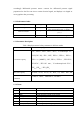
1.5.2 Performance index
Measurement parameters
Range
Maximum indication error
Expiration /inspiration flow
( 0-16 ) L/s
± 5% or ± 0.17L/s , whichever is greater
Airflow resistance
/
Flow measurement range < 0.15 kPa /
( L/s )
Volume
( 0-10 ) L
± 3% or ± 0.05L , whichever is greater
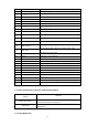
1.5.3 Parameter description
Table 1 Display measured value parameters in different modes
Model
Measurement display parameters
Forced vital capacity
FVC、FEV
0.5
、FEV
1
、FEV
3
、FEV
6
、V backextrapol. ex、
FIVC(FVC IN)、FIV
1
、PEF、FEF
25%
、FEF
50%
、FEF
75%
、
FEF
25%-75%
(MMEF)、PIF、FIF
50%
、FET
100%
、FEV
1
/FVC、
FEV
3
/FVC、 FEV
1
/VC max、 V backextrapol.ex% FVC、
FEF
50%
/FIF
50%
、FEV
1
/FIV
1
Slow vital capacity
VC max、VC in、VC ex、IC、IRV、VT、ERV、MV、BF
Maximum minute
ventilation
VT MVV、MVV、TIME MVV、BF MVV
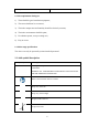
1.5.4 Terms
Number
Abbreviation
Full Name
1-1
FVC
forced vital capacity
1-2
FEV
0.5
forced expiratory volume in half a second
1-3
FEV
1
forced expiratory volume in one second
1-4
FEV
3
forced expiratory volume in three seconds
1-5
FEV
6
forced expiratory volume in six seconds
1-6
V backextrapol.ex
back extrapolated volume
1-7
FIVC(FVC IN)
forced inspiratory vital capacity