
Data Sheet
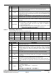
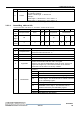
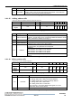
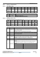
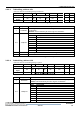
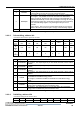
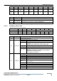
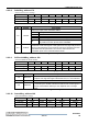
Table Of Contents
- Contents
- Tables
- Figures
- 1 Product Overview
- 2 Functional Description
- 3 FM17520 Register Set
- 4 Host Interfaces
- 5 Analog Interface And Contactless UART
- 6 CRC Coprocessor
- 7 FIFO Buffer
- 8 Interrupt Request System
- 9 Timer
- 10 Power Reduction Modes
- 11 Low Voltage Detection
- 12 Oscillator Circuitry
- 13 Reset And Oscillator Start-Up Time
- 14 Command Set
- 15 Testsignals
- 16 Typical Application Diagram
- 17 Characteristics
- 18 Ordering Information
- 19 Package Information
- Revision History
- Sales and Service

3 FM17520 Register Set
Datasheet
FM17520 Contactless Transceiver IC Ver 1.0 21
Bit
Symbol
Description
4
BufferOvfl
Set to logic 1, if the host controller or a FM17520’s internal state machine
(e.g. receiver) tries to write datainto the FIFO-bufferalthough the
FIFO-buffer is already full.
3
CollErr
Set to logic 1, if a bit-collision is detected. It is cleared automatically at
receiver start-up phase. This bit is only valid during the bitwise anticollision
at 106 kbit/s. During communication schemes at 212 and 424kbit/s this bit
is always set to logic 1.
2
CRCErr
Set to logic 1, if bit RxCRCEn in register RxModeReg is set and the CRC
calculation fails. It is cleared to 0 automatically at receiver start-up phase.
1
ParityErr
Set to logic 1, if the parity check has failed. It is cleared automatically at
receiver start-up phase. Only valid for ISO/IEC 14443A communication at
106 kbit/s.
0
ProtocolErr
Set to logic 1, if one out of the following cases occur:
Set to logic 1 if the SOF is incorrect. It is cleared automatically at
receiver start-up phase. The bit is only valid for 106kbit/s in
Communication mode.
During the Authent Command, bit ProtocolErr is set to logic 1, if the
number of bytes received in one data stream is incorrect.
Tab3-17 ErrorReg bits description
3.2.1.8 Status1Reg_address 07h
Contain status bits of the CRC, Interrupt and FIFO buffer.
Bit
7
6
5
4
3
2
1
0
Definition
RFU
CRCOk
CRCReady
IRq
TRunning
RFU
HiAlert
LoAlert
Access
Rights
-
r
r
r
r
-
r
r
Reset
Value
0
0
1
0
0
0
0
1
Tab3-18 Status1Reg register
Bit
Symbol
Description
7
-
Reserved for future use.
6
CRCOk
Set to logic 1, if the CRC Result is zero. For data transmission and
reception the bit CRCOk is undefined (use CRCErr in register ErrorReg).
CRCOk indicates the status of the CRC coprocessor, during calculation
the value changes to 0, when the calculation is done correctly, the value
changes to 1.
5
CRCReady
Set to logic 1, when the CRC calculation has finished. This bit is only valid
for the CRC coprocessor calculation using the command CalcCRC.
4
IRq
This bit shows, if any interrupt source requests attention (with respect to
the setting of the interrupt enable bits, see register CommIEnReg and
DivIEnReg).
3
TRunning
Set to logic 1, if the FM17520’s timer unit is running. (The timer will
decrement the TCounterValReg with the next timer clock.)
Remark: In the gated mode the bit TRunning is set to logic 1, when the
timer is enabled by the register bits. This bit is not influenced by the gated
signal.
2
-
Reserved for future use.
1
HiAlert
Set to logic 1, when the numberof bytes stored in the FIFO-buffer fulfills
the following equation:
HiAlert = (64 – FIFOLength ) ≤ WaterLevel
Example:
FIFOLength = 60, WaterLevel = 4 HiAlert = 1
FIFOLength = 59, WaterLevel = 4 HiAlert = 0