
Data Sheet
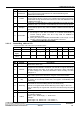
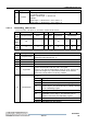
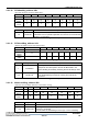
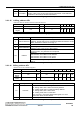
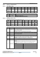
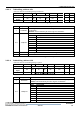
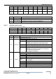
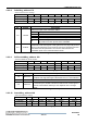
Table Of Contents
- Contents
- Tables
- Figures
- 1 Product Overview
- 2 Functional Description
- 3 FM17520 Register Set
- 4 Host Interfaces
- 5 Analog Interface And Contactless UART
- 6 CRC Coprocessor
- 7 FIFO Buffer
- 8 Interrupt Request System
- 9 Timer
- 10 Power Reduction Modes
- 11 Low Voltage Detection
- 12 Oscillator Circuitry
- 13 Reset And Oscillator Start-Up Time
- 14 Command Set
- 15 Testsignals
- 16 Typical Application Diagram
- 17 Characteristics
- 18 Ordering Information
- 19 Package Information
- Revision History
- Sales and Service

3 FM17520 Register Set
Datasheet
FM17520 Contactless Transceiver IC Ver 1.0 23
3.2.1.10 FIFODataReg_address 09h
Input and output port of 64 byte FIFO buffer.
Bit
7
6
5
4
3
2
1
0
Definition
FIFOData
Access
Rights
dy
dy
dy
dy
dy
dy
dy
dy
Reset
Value
x
x
x
x
x
x
x
x
Tab3-22 FIFODataReg register
Bit
Symbol
Description
7-0
FIFOData
Data input and output port for the internal 64 byte FIFO buffer. The
FIFO buffer acts as parallel in/parallel out converter for all serial data
stream in- and outputs.
Tab3-23 FIFODataReg bits description
3.2.1.11 FIFOLevelReg_address 0Ah
Indicate the number of bytes stored in the FIFO.
Bit
7
6
5
4
3
2
1
0
Definition
FlushBuffer
FIFOLevel
Access
Rights
w
r
r
r
r
r
r
r
Reset
Value
0
0
0
0
0
0
0
0
Tab3-24 FIFOLevelReg register
Bit
Symbol
Description
7
FlushBuffer
Set to logic 1, this bit clears the internal FIFO buffer’s
read-pointer and write-pointer and the bit BufferOvfl in the
register ErrReg immediately. Reading this bit will always return
0.
6-0
FIFOLevel
Indicate the number of bytes stored in the FIFO-buffer. Writing
to the FIFODataReg increments, reading decrements the
FIFOLevel.
Tab3-25 FIFOLevelReg bits description
3.2.1.12 WaterLevelReg_address 0Bh
Define the level for FIFO underflow and overflow warning.
Bit
7
6
5
4
3
2
1
0
Definition
RFU
RFU
WaterLevel
Access
Rights
-
-
r/w
r/w
r/w
r/w
r/w
r/w
Reset
Value
0
0
0
0
1
0
0
0
Tab3-26 WaterLevelReg register
Bit
Symbol
Description
7-6
-
Reserved for future use.
5-0
WaterLevel
This register defines a warning level to indicate a FIFO buffer
overflow or underflow.
The bit HiAlert in Status1Reg is set to logic 1, if the remaining