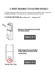
Smart Door Lock S110BBL-F FOR CUSTOMER SERVICE PLEASE CALL: (800)-315-9607 WWW.ELEMAKELOCKS.COM Elemake keeps on working hard to provide customers top-grade quality hardware at affordable price. Gracing customers’ doors with stylish designs and excellent craftsmanship since 1976, Elemake is always dedicated to making your life more safe and stylish.
Series-ITD locks are a family of touch screen and fingerprint internet deadbolts. They are ideal for residential homes, apartment buildings, offices, schools, hospitals, and other applications where restricted access to an area is needed. All of ELEMAKE ITD series keyless deadbolt products come with a 5 years’ warranty. NOTE TO INSTALLER Watching the videos are highly recommended, the video will help the customer to understand the installation and functions more easily.
Initial Password: 123456
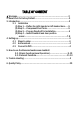
TABLE OF CONTENT 1. Warnings……………………………………………………………………………..2 2. Reset Lock To Factory Default...........................................................3 3. Introduction.....................................................................................4 3.1 Installation (1) Step 1----Define the right-handed or left-handed door……5 (2) Step 2----Components and Tools…………………………………5 (3) Step 3----Prepare Deadbolt for Installation………….……....6 (4) Step 4 ---Install Deadbolt and door position sensor ……..
1. WARNINGS FCC: Class B Equipment Series ITD series deadbolt has been tested and found to comply with the limits for a Class B digital device---Part 15 of the FCC Rules. These limits are purposed to provide protection against harmful interference in a residential environment. The deadbolt generates, uses, and can radiate RF energy and, if not installed and used as the instructions on users’ manual, may have harmful interference to radio communications.
2. RESET DEADBOLT TO FACTORY DEFAULT The following procedure clears all the setting of the deadbolt, and returns the deadbolt to default – deleting all user password/fingerprint/card. 2.
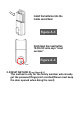
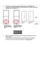
Install the batteries into the inside escutcheon Figure A-3 Hold down the reset button 10-30s till voice says “reset success” Figure A-4 2.
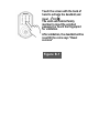
Touch the screen with the back of hand to activate the deadbolt,and input 888 , The voice will remind family member to input the enrolled password or touch the fingerprint for validation.
3. INSTALLATION IMPORTANT THINGS INSTALLER NEED TO KNOW PRIOR TO INSTALLATION a. b. Initial password “123456” Bolt Direction Please make sure the bolt is installed in correct direction according to ”up” mark on the bolt. (see Figure C1) Figure C-1 c. The bolt must be in a retracted (unlocked) position when installing the lockset. (see Figure C2) Figure C-2 d.
e. Thumb turn on inside escutcheon need to be turned to different position for right handed door or left handed door in inside escutcheon installation. (see Figure C-5) Vertical Position For Right Handed Door Horizontal Position For Right Handed Door Figure C-5 f. Before installing the batteries, test the mechanical operation of the lock by using Both thumb turn and the key. The movement of the bolt should be smooth and unobstructed.
Figure C-6 g.
h. Assembly drawing(See Figure C-8) Figure C-8 3.1 STEP 1----DEFINE THE RIGHT HANDED OR LEFT HANDED DOOR. To Ensure Proper Lock Handing and for an explanation of how to determine your lock handing, please read this important note.
Figure 3I Inside Left-Handed Door Right –Handed Door Outside Figure D-1 3.
Figure E-1 (2) Tools Needed 2-1/8" (54mm) hole saw 1" (26mm) boring bit Wood screw drill bit Chisel & hammer 3.
Use a pin to press down the button to slide up the battery cover to take off the batteries Figure F-1 (2) Mount Plate(See Figure F-2) This circled position is the wire slot which will allow the cable from the outside escutcheon to go through in installation Figure F-2 (3)Bolt(See Figure F-3) Bolt can be adjusted to either 2-3/8 or 2-3/4 by twist the head
Press small black button on underside of bolt and pull to extend to 2-3/4" backset position. Figure F-3 (4) Outside escutcheon The outside escutcheon (with gasket) remains assembled(see Figure F-4). Figure F-4 3.4 STEP 4----INSTALL DEADBOLT & Door Position Sensor (1) Install bolt in door.(see Figure G-4, Figure G-5, Figure G-6) NOTE: THE BOLT MUST BE IN A RETRACTED (UNLOCKED) POSITION PRIOR TO INSTALLING THE LOCKSET.
Use 25mm wood screw to secure the bolt onto the door.
Install strike on the door frame, making sure to allow for the bolt to be centered in the strike.
Figure H-2 The cable need to go under the bolt in installation Holding the outside escutcheon flush to the door, position the inside mounting plate by first routing the cable and connector through the mounting plate's wire slot on the side Insert the mounting plate “tongue” into the bottom slot of the outside escutcheon Secure both assemblies using (2)40mm machine screws Figure H-3
Figure H-4 Cable from outside escutcheon should go though the right side slot of the mount bracket (3) Route cable(see Figures I-1 and Figure I-2, Figure I-3). (a) Attach cable assembly to the inside escutcheon printed circuit board (PCB) by lining up notches on top of cable connector to slots on PCB connector (Figure 3K). Press connector in firmly using thumbs until completely seated (proper position indicated by arrows on PCB as in (see Figures I-1 and Figure I-2, Figure I-3).
Door Position Sensor Connector/cable Figure I-2 Outside Escutcheon Cable/Connector Figure I-3 (4) Install inside escutcheon and door position sensor(For automatic relocking) (see Figure J-1, Figure J-2, Figure J-3, Figure J-4 Figure J-5 ,Figure J-6, Figure J-7) IMPORTANT: Before installing the batteries, test the mechanical operation of the lock by using both thumb turn and the key. The movement of the bolt should be smooth and unobstructed.
For right handed or left handed door, the thumb turn need to be put in different position prior to installation. And please make sure the bolt is retracted for installation.
For user need automatic relocking function------Install the door position sensor on the side of the door, another part(magnet) need to be installed opposite to the door position sensor. The center of the door position sensor and the magnet need to be aligned in same line. If user want to use manual relocking, just don’t install the door position sensor. Figure J-4 IMPORTANT: Before installing the batteries, test the mechanical operation of the lock by using both thumb turn and the key.
Insert four (4) AA alkaline batteries. The lock keypad will be lighted up. When activating the lock for the first time, please set the rotation direction of the lock Slide on the battery cover till a “click”. Figure J-6 IMPORTANT: CHOOSE MOTOR ROTATION DIRECTION After the above installation steps, connect the deadbolt to Smartlife APP (see 4.1---(1) and 4.
Choose COUNTERCLOCKWISE for RIGHT HANDED DOOR Choose CLOCKWISE for LEFT HANDED DOOR Figure J-7
4. SETTING UP WITH APP 4.1 STEPS TO SET UP WITH SMART LIFE APP. (1) Step 1---earch “Smartlife” APP, download and register and log in. (See Figure K-1) Figure K-1 (2) Step 2--Connect the deadbolt to mobile phone App Smartlife with Bluetooth (See Figure L-1, Figure L-2, Figure L-3 ,Figure L-4) (a) Turn on the bluetooth on celluar phone. (b) Touch the screen with back of your hand to activate the deadbolt.
(d) Click the deadbolt’s logo to connect the deadbolt, Name the deadbolt and save. .
Figure L-3 (e) If successfully connected the Smartlife app with the deadbolt. The opening button on the screen will turn to green colored . User can use the mobile phone to unlock the deadbolt via the Bluetooth.
Figure M-1 (4) 4.2 Add member(See Figure N-1) (a) At the home page of the deadbolt, click “add member” (b) Choose member type Family member(administrators)----- the family member with fully authorized, be able to control and use all devices Other member----with the limited authority by the family member(administrator). (c) Invite member Send out the invitation to be member via social messengers including the invitation verification code..
Figure N-1
Figure N-1 4.
(b) Setup the Tuya Wifi gateway. (optional)(any wifi gateway with Tuya gateway IC) --If user want to use the internet functions.
5. HOW TO USE THE DEADBOLT NOTE: For most of the functions, user can follow the steps in the app to easily learn how to use the smart deadbolt with common sense, for specific operation, also can refer to below detailed instructions. 5.1 Basic Functions (1) Password unlocking(See Figure P-1) (a) Touch the screen with the back of your hand or fingers to activate (b) Start with entering “I” write key, Enter password.
(1) Fingerprint unlocking(See Figure P-2) Put the finger on the fingerprint reader. Deadbolt will be automatically unlocked. Figure P-2 (2) Key unlocking (See Figure P-3) Remove the lid with the suction tool, use the key to unlock.
(3) RF card unlocking (See Figure P-1) Put the RF card to the middle of the escutcheon, user can hear the “beep”, then deadbolt will be automatically unlocked. 5.1.6 Bluetooth Remote Unlocking with Mobilephone APP. Turn on the bluetooth of the celluar phone.
Off-line reusable temporary password unlocking (5) Temporary power to outside escutcheon(See Figure P-4) If user did not change the battery timely, when battery is drained, user still can temporarely supply the power to the lock with power bank and Type C charging line from the bottom of outside escutcheon. Figure P-3 (6) Lock the door/Relock(See Figure P-5, Figure P-6) a.
sensor. b. If user want to use the manual locking/relocking, When door is closed, user touch the “lock”, deadbolt will lock. (See Figure P-6) Figure P-6 (7) Battery level monitoring(real time) (See Figure P-7) User can easily read the percentage of the battery level when turn on the Tuya smart APP and enter the lock page. At the top of the page, there is the percentage of the battery.
(8) Record of deadbolt unlocking history(See Figure P-8) Enter the lock’s page, click the “opening record” at the page bottom, user can see all unlocking records with the family member information. Figure P-8 (9) Choose Languages(See Figure P-9) There are 2 languages options.
5.2 INTERNET FUNCTIONS (1) Separated WIFI design, No Power consumption to battery for WIFI application. (See Figure Q-1) If customer want to use Internet functions, user can purchase the Tuya Wifi gateway from us, separated WIFI bridge (110V wall plug) avoids the high power consumption of the WIFI to use the battery energy, will not consume the battery power in deadbolt.
If the user already connected the deadbolt to Tuya Wifi gateway, the long distance unlocking function will work where ever you are located as long as there is Internet.. Figure Q-3 (4) Go home alert/door abnormal alert. (See Figure Q-4) Click “smart linkage” on the deadbolt’s home page.>scene>SceneEdit Then to set up the alert. When the door is opened or in abnormal status, user will get the message/voice or other notification.
Figure Q-5 (6) Smart Home Can be use a with Tuya/SmartHome as a related items which can be a part of the smart home system.
6. TROUBLE SHOOTINGS Troubleshooting (See Figure R-1) Figure R-1 7. QUALITY POLICY We provide a 5 years warranty for all of our Keyless door lock products from the day of purchase. Return/replacement Policy If you want to return/replace the goods for any reason, please contact us directly for return/replacement. In this way, EleMake will be able to pay for the returning shipping cost to avoid loss to any customers.
LIMITED WARRANTY LIMITED WARRANTY OF THE LOCK PRODUCTS With seller warrant to the original purchaser only, that the lock products will be free from defects in material or workmanship for a period of two ( 5) years from the date of purchase. 1years for the products, if the tool i s used for professional use.
There must also be a description of the problem in order to help our repairs department diagnose and fix the issue. Repairs will be made an d the product will be returned and shipped back to the purchaser at no c harge. THIS LIMITED WARRANTY DOES NOT APPLY TO ACCESSORY ITE MS THAT WEAR OUT FROM REGULAR USAGE OVER TIME INCLU DING SANDING PADS, DISC PAPERS, BELTS, BRUSHES, BLADES, ETC. ANY IMPLIED WARRANTIES SHALL BE LIMITED IN DURATION TO ONE (1) YEAR FROM THE DATE OF PURCHASE. SOME STATES IN THE U.S.
A, AND FROM COUNTRY TO COUNTRY. THIS LIMITED WARRANTY APPLIES ONLY TO PORTABLE ELECTRI C TOOLS, BENCH POWER TOOLS, OUTDOOR POWER EQUIPMEN T, AND PNEUMATIC TOOLS SOLD WITHIN THE UNITED STATES O F AMERICA, AND CANADA.
www.elemakelocks.com EleMake Lock Products. Online customer service---Facebook #:csservice168@163.com Skype #: customerservice@products Email-address: customerservice@elemakelocks.
This device complies with part 15 of the FCC Rules. Operation is subject to the following two conditions: (1) This device may not cause harmful interference, and (2) this device must accept any interference received, including interference that may cause undesired operation. Any Changes or modifications not expressly approved by the party responsible for compliance could void the user's authority to operate the equipment.