
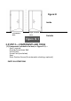
Installation Instructions


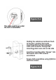

(3) Route cable(see Figures I-1 and Figure I-2, Figure I-3).
(a) Attach cable assembly to the inside escutcheon printed circuit board
(PCB) by lining up notches on top of cable connector to slots on PCB
connector (Figure 3K). Press connector in firmly using thumbs until
completely seated (proper position indicated by arrows on PCB as in
(see Figures I-1 and Figure I-2, Figure I-3).
(b) If need automatic relocking function, need to install the door position
sensor(supplied in the box), attach the sensor cable to the inside
escutcheon printed circuit board (PCB), the cable route through the
slot on the rubber gasket. (see Figures I-1 and Figure I-2).
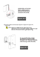
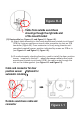
Cable from outside escutcheon
should go though the right side slot
of the mount bracket
Cable and connector for door
position sensor (Optional for
automatic relocking)
Outside escutcheon cable and
connector
Figure H-4
Figure I-1