PRODUCT MANUAL 6 beamLabs.
TABLE OF CONTENTS Congratulations on purchasing your beamUP garage door opener. It will provide you with many years of security, safety and convenience. This installation and owner’s manual contains complete instructions for installing and operating your garage door opener. Carton Contents . . . . . . . . . . . . . . . . . . . . . . . . . . . . . . . . . . . . . . . . . . . . 1 Before You Begin . . . . . . . . . . . . . . . . . . . . . . . . . . . . . . . . . . . . . . . . . .
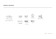
CARTON CONTENTS Clevis Pin Hitch Pin Lag Screw 5/16"- 1/1/2" Bolt Flange Nut Self-Threading Screw - 1/4” x 5/8” (BSBHF %PPS 0QFOFS 6 Anchors 5/16” - 18x1" beamLabs.
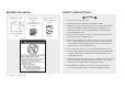
BEFORE YOU BEGIN SAFETY INSTRUCTIONS WARNING Measure door height. 7.5 feet h (2.28 m) If over 7.5 feet (2.28 m), rail extension kit will be needed. Check mounting locations. Are additional reinforcement material needed? Check your toolbox. Do you have all the tools needed? See page 3 See page 3 To reduce the risk of severe injury or death: 1. READ AND FOLLOW ALL INSTALLATION INSTRUCTIONS. 2. Install only on a properly balanced garage door.
PREPARE GARAGE DOOR FOR INSTALLATION TOOLS NEEDED DO NOT REUSE PARTS AND WIRING FROM AN OLD OPENER!!! Level BEFORE beginning installation: Adjustable Wrench 1. Disable locks and disengage trolley from current opener. 2. Perform the following door test to ensure your door is balanced and in good working condition.
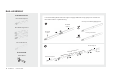
RAIL ASSEMBLY Look in the box for: Rail – Header Segment Connect rails starting with the rail header segment. To apply additional force tap gently on the end of the rail with a rubber mallet or on padded flooring. Securely connected by applying force Rail- Middle Segment Rail – Middle Segments x3 Right Rail- Header Segment Loosely connected ed Wrong Rail – End Segments Rail- End Segment 3BJM &OE 4FHNFOU &OE 4FHNF x3 en OtsUT Y gmF dMFle 4SFeHN id E M JE il 3BRJMa .
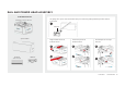
RAIL AND POWER HEAD ASSEMBLY Look in the box for: (BSBHF %PPS 0QFOFS 6 Use garage door opener carton to assemble rail to power head. Use packing material as protective base for power head. Rail Bracket 3BJM #SBDLFU Opener Carton p Align and slide rail into rail bracket as shown. Insert clevis pin into rail bracket as shown. Insert hitch pin into clevis pin as shown. U Clevis Pin 3/8" x 1-3/4" Hitch Pin beamLabs.
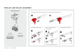
TROLLEY AND PULLEY ASSEMBLY Look in the box for: Slide Trolley onto the rail. Make sure the arrow on the trolley points toward the door. Trolley Pulley Insert pulley into the rail slot. Clevis Pin 3/8" x 1-3/4" beamLabs.io 1-800-436-9186 Insert hitch pin into clevis pin. Hitch Pin 6 Insert clevis pin through rail hole and pulley.
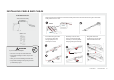
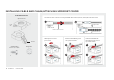
INSTALLING CABLE AND CHAIN Look in the box for: Chain/Cable Assembly Align end of chain around sprocket and extend chain past chassis. Pull chain with box along the rail towards trolley and then remove box. Chassis $IBTTJT Master Link Insert cable through circular hole in trolley. Pull cable through pulley slot and toward power head. Pull trolley lock lever down to unlock. Insert trolley shaft into trolley. Lock trolley shaft in trolley by pulling lever back up.
INSTALLING CABLE AND CHAIN/ATTACHING SPROCKET COVER Look in the box for: Turn chain-to-cable connector on trolley shaft until chain is about 1/4 inch (.64 cm) above the base of rail. Sprocket Cover Front Tab Tighten until... 5JHIUFO VOUJM Chain-to-cable connector 1/4 inch (.64 cm) Attach sprocket cover to power head. Rear Tab Self-Threading Screw - 1/4" x 5/8" G 8 beamLabs.io 1-800-436-9186 Flange Nut Fasten rear tab with flange nut on top of steel chassis.
MOUNTING HEADER BRACKET Look in the box for: Header Bracket 2 x Lag Screw 5/16" x 1-1/2" Above door, mark the center line of the door with a pencil, through wall. Open door to the highest point of travel. Highest Point of Travel $FOUFS -JOF Center Line WARNING To prevent SERIOUS INJURY: • DO NOT connect power until instructed. • The header bracket MUST be SECURELY fastened to the structural support on the mounting wall or ceiling, otherwise other door may not reverse when required.
ATTACHING RAIL AND MOUNTING DOOR BRACKET Look in the box for: Hitch Pin Clevis Pin 3/8" x 1-3/4" Use garage door opener carton to support power head. Rail return pulley end should be pointing to header bracket. Align header rail hole to header bracket hole. Header Header )FBEFS Rail Hole 3BJM )PMF Door Bracket 2 x Self-Threading Screw - 1/4" x 5/8" )FBEFS Bracket Hole #SBDLFU )PMF Center Line $FOUFS -JOF Connect header rail and header bracket with clevis pin and secure with hitch pin.
MOUNTING POWER HEAD TO CEILING Need rewritten text Look in the box for: 4 x Lag Screw 5/16" x 1-1/2" / / 4 x Bolt 5/16" 5/16 - 18 x 1" 1 4 x Flange Nut Hanging Brackets (not supplied) Raise power head and place it on top of step ladder. Position and align power head with rail assembly to centerline. B C Structural Support 4USVDUVSBM 4VQQPSU D Three most common installation options. Determine the mounting option that works best for you. Fasten angle iron to stud under a finished ceiling.
ATTACHING DOOR ARMS LLook in the box for: Curved rved Doorr A Arm Straight Door Arm 2 x Hitch Pin H 2 x Clevis Pin 3/8" x 1" 2 x Bolt 5/16" - 18 x 1" 2 x Flange Nut Close your garage door and disengage trolley. Fasten curved door arm to the door bracket with 5/16" x 1" clevis pin and secure with hitch pin. Fasten straight door arm to trolley with a 5/16" x 1" clevis pin and secure with hitch pin. Attached door arms fasten with two 5/16" bolts and flange nuts.
INSTALLING EMERGENCY RELEASE HANDLE Look in the box for: Emergency rgency gency Releas Release Han Handle * VERY IMPORTANT! * Emergency release handle must clear all vehicles. An Emergency release handle set too low may get caught by the vehicle and cause damage to the opener. Measure from the floor to the top of your vehicle and set the emergency release handle above this measurement. Thread end of rope through handle and secure with an over hand knot. Thread end of the rope through hole in trolley lever.
CONNECTING PHOTO EYE SAFETY SYSTEM Look in the box for: Photo Eyes 4x Screw #12 x 1-1/4" Mount photo eyes. Run wire to head. Use insulated staples to secure photo eyes’ wire to wall or ceiling. Be careful not to damage the wires while securing staples. Photos eyes should be no more than 6 G inches (15.2 cm) above the floor.
CONNECTING POWER AND ALIGNING PHOTO EYE SAFETY SYSTEM WARNING To prevent SERIOUS INJURY or DEATH from electrocution or fire: • Power MUST be DISCONNECTED BEFORE proceeding with permanent wiring procedures. * DO NOT OPERATE OPENER AT THIS TIME * Plug power head into a grounded outlet ONLY. If there is no grounded outlet present, call a qualified electrician to replace the outlet. Use of a surge protector is highly recommended.
CONNECTING DELUXE DOOR CONTROL (BU400, BU800) Look in the box for: Deluxe Door Control* 2x Screw #6 x 1-3/8" 1. Strip 7/16 inch (11 mm) of insulation from wire and separate wires. Wire deluxe door control to power head as shown. 2. Connect one wire to each of the two screws on the back of the door control. **DO NOT USE PRE-EXISTING WIRE** Deluxe Door Control 3. Mark the location of bottom mounting hole and drill 5/32 inch hole.
MOTION ACTIVATED SECURITY LIGHTING (BU400, BU800) Security lighting is activated and remains on for 4.5 minutes when garage door opener is operated. Motion sensing is turned on by default and will activate security lighting when motion is detected within the garage. Security lighting will remain illuminated for 4.5 minutes or for as long as there is motion in the garage. Need images To deactivate motion sensing: Press and hold “LIGHT” button for 2 seconds.
CONNECTING STANDARD DOOR CONTROL (BU100) Look in the box for: Standard Door Control* 2x Screw #6 6 x 11-3/8" 3/8 Wire standard door control to opener as shown. Standard Door Control 1. Strip 7/16 inch (11 mm) of insulation from wire and separate wires. 2. Connect one wire to each of the two screws on the back of the door control. **DO NOT USE PRE-EXISTING WIRE** 3. Mark the location of bottom mounting hole and drill 5/32 inch hole.
TRAVEL LIMIT ADJUSTMENT - UP LIMIT Need text from up down limit 110518 PDF WARNING To prevent SERIOUS INJURY or DEATH from improper Force Adjustment: • YOU CANNOT adjust force manually to compensate for binding or sticking of the garage door. Call a qualified garage door service person to make necessary adjustments in case of binding. Press and Release LIMIT button once, green light (UP) will turn on. With green light on, press and hold UP button, the door will go UP to the desired UP limit position.
TRAVEL LIMIT ADJUSTMENT - DOWN LIMIT Need text from up down limit 110518 PDF WARNING To prevent SERIOUS INJURY or DEATH from improper Force Adjustment: • YOU CANNOT adjust force manually to compensate for binding or sticking of the garage door. Call a qualified garage door service person to make necessary adjustments in case of binding. Press and Release LIMIT button TWICE, red light (DOWN) will turn on.
SETTING THE FORCE Need text from up down limit 110518 PDF WARNING To prevent SERIOUS INJURY or DEATH from improper Force Adjustment: With both UP and DOWN lights on, press and release the FORCE button once to enter Auto Force Setting. • YOU CANNOT adjust force manually to compensate for binding or sticking of the garage door. Call a qualified garage door service person to make necessary adjustments in case of binding. • YOU CANNOT manually increase the force required for closing the door.
FINAL ADJUSTMENTS AND TESTING WARNING To prevent SERIOUS INJURY or DEATH from a closing garage door: Open door using door control. Place a 1-1/2 inch (3.8cm) flat solid object on the floor, centered under the garage door. • The Safety Reversal Test MUST be conducted ONCE A MONTH. • NO ONE should cross the path of moving door during operation and/or testing. • After ANY adjustments to the door system, the Safety Reverse Test MUST be performed to ensure the door reverses on contact with a 1-1/2 inch (3.
SPARE PARTS B """ C """ $MFWJT 1JO )JUDI 1JO 4FMG 5ISFBEJOH 4DSFX 'MBOHF /VU -BH 4DSFX "ODIPS #PMU /05& /PU "WBJMBCMF BT JOEJWJEVBM QBSUT beamLabs.
OPENER ASSEMBLY PARTS )&& ^ƚĂƚĞŵĞŶƚ˖ $Q\ &KDQJHV RU PRGLILFDWLRQV QRW H[SUHVVO\ DSSURYHG E\ WKH SDUW\ UHVSRQVLEOH IRU FRPSOLDQFH FRXOG YRLG WKH XVHU¶V DXWKRULW\ WR RSHUDWH WKH HTXLSPHQW 7KLV GHYLFH FRPSOLHV ZLWK SDUW RI WKH )&& 5XOHV 2SHUDWLRQ LV VXEMHFW WR WKH IROORZLQJ WZR FRQGLWLRQV 7KLV GHYLFH PD\ QRW FDXVH KDUPIXO LQWHUIHUHQFH DQG WKLV GHYLFH PXVW DFFHSW DQ\ LQWHUIHUHQFH UHFHLYHG LQFOXGLQJ LQWHUIH