
User's Manual


7
Section 2 – Operation
Recreational Vehicle Generators
1.6.5 EMISSIONS COMPLIANCE PERIOD
For nonhandled engines the Emissions Compliance
Period referred to on the Emissions Compliance
Label indicates the number of operating hours for
which the engine has been shown to meet Federal
emission requirements.
• For engines less than 225 cc displacement, Category
C=125 hours, B=250 hours, and A=500 hours.
• For engines of 225 cc or more, Category C=250
hours, B=500 hours, and A=1000 hours.
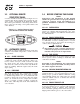
2.1 GENERATOR CONTROL PANEL
The following features are mounted on the generator
control panel (Figure 2.1):
2.1.1 FUEL PRIMER
Before starting a cold engine (if it has not been
started in more than two weeks), press this switch
for approximately ten seconds to bring fuel from
the tank to the fuel pump. This rocker type switch
springs back into its original position when it is
released.
2.1.2 START/STOP SWITCH
To crank and start the engine, hold this switch in the
START position. Release the switch when the engine
starts. To stop an operating engine, press and hold
the switch in the STOP position until the engine shuts
off. The switch center position is the RUN position.
2.1.3 7.5 AMP FUSE
The fuse protects the engine’s DC control circuit
against electrical overload. If the fuse element has
melted open due to overloading, the engine cannot
be cranked. If the fuse must be replaced, use only an
identical 7.5 amp replacement fuse.
2.1.4 LINE BREAKERS
Protects generator’s AC output circiut against over-
load, i.e., prevents unit from exceeding wattage/
amperage capacity. The circuit breaker ratings are
as follows:
NOTE:
If this generator has been reconnected for dual
voltage AC output (120/240 volts), install line
breakers having an amperage rating that is differ-
ent than that stated above. The replacement line
breakers consist of two separate breakers with a
connecting piece between the breaker handles (so
that both breakers will operate at the same time).
If the unit is reconnected for dual voltage, it is no
longer RVIA or CSA listed.
Figure 2.1 – Typical Control Panel
P
R
I
M
E
S
T
O
P
S
T
A
R
T
F
U
E
L
F
S
E
7
.
5
A
0
E0580 REV. B
CO
NTR
O
L
C
ENTE
R
C
I
R
U
I
T
B
R
E
A
K
E
R
B
R
A
K
E
R
C
I
R
U
I
T
PRE
SS
PRIME
S
WIT
C
H F
O
R 1
0
S
E
CO
ND
S
BEFORE STARTING. WHEN STARTING
,
DO NOT PRESS
S
TART B
U
TT
O
N L
O
N
G
ER THEN 1
5
S
E
CO
ND
S
PER ATTEMPT
.
IF
G
ENERAT
O
R D
O
E
S
N
O
T
S
TART
.
REM
O
VE AND IN
S
PE
C
T F
US
E
.
(
SEE OWNER'S MANUAL TROUBLE SHOOTING GUIDE.
)
1.6.3 GENERATOR SPECIFICATIONS
SERIES QP55G QP55LP QP65G QP65LP QP75G QP75LP
Rotor RPM 3600 3600 3600 3600 3600 3600
Rotor Poles 2 2 2 2 2 2
Engine RPM 2200 2200 2571 2571 2571 2571
Rated Max. Continuous AC Output Watts* 5500 5500 6500 6500 7500 7500
Voltage* 120 120 120 120 120 120
Rated Max. Continuous Current Amps (240V) 45.8 (22.9) 45.8 (22.9) 54.1 (27.0) 54.1 (27.0) 62.5 (31.2) 62.5 (31.2)
Phase 1 1 1 1 1 1
Frequency 60 Hertz 60 Hertz 60 Hertz 60 Hertz 60 Hertz 60 Hertz
Battery Charging Current (Max.) 2 amps 2 amps 2 amps 2 amps 2 amps 2 amps
Weight 326 lbs. 329 lbs. 328 lbs. 331 lbs. 330 lbs. 333 lbs.
Length 33.7 in. 33.7 in. 33.7 in. 33.7 in. 33.7 in. 33.7 in.
Width 22.2 in. 22.2 in. 22.2 in. 22.2 in. 22.2 in. 22.2 in.
Height 19.6 in. 19.6 in. 19.6 in. 19.6 in. 19.6 in. 19.6 in.
* All units are reconnectable to 120 and/or 240 volts, dual voltage output. Units are not listed per RVIA/ANSI when reconnected for dual voltage output
Model Circuit Breaker 1 Circuit Breaker 2 240 Volt
QuietPact 55 30A 20A 25A 2P
QuietPact 65 30A 30A 30A 2P
QuietPact 75 35A 35A 35A 2P