
- Guardian Technologies, LLC Portable Generator User Manual

8 Generac
®
Power Systems, Inc.
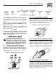
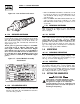
NOTE:
Port 1 is for NG only and Port 2 is for LP vapor
only. No provision for simultaneous fuels has been
made.
Serious injury or damage may occur if not con-
figured properly. Please consult an authorized
Generac Service Dealer with any questions.
1.13 TORQUE SPECIFICATIONS
Cylinder Head ............................................15 (+ 90° + 90°) ft.lb.
Intake Manifold ................................................................13 ft.lb.
Exhaust Manifold..............................................................13 ft.lb.
1.14 ENGINE OIL RECOMMENDATIONS
The unit has been filled with 15W-40 engine oil at the
factory. Use a high-quality detergent oil classified “For
Service CC, SD, SE, SF.” Detergent oils keep the engine
cleaner and reduce carbon deposits. Use oil having the
following SAE viscosity rating, based on the ambient
temperature range anticipated before the next oil
change:
Any attempt to crank or start the engine before
it has been properly serviced with the recom-
mended oil may result in an engine failure.
1.15 COOLANT RECOMMENDATIONS
Use a mixture of half low silicate ethylene glycol base
anti-freeze and deionized water. Cooling system
capacity is about 8 U.S. quarts (7.6 liters). Use only
deionized water and only low silicate anti-freeze. If
desired, add a high quality rust inhibitor to the rec-
ommended coolant mixture. When adding coolant,
always add the recommended 50-50 mixture.
Do not use any chromate base rust inhibitor
with ethylene glycol base anti-freeze or chromi-
umhydroxide (“green slime”) forms and will
cause overheating. Engines that have been
operated with a chromate base rust inhibitor
must be chemically cleaned before adding eth-
ylene glycol base anti-freeze. Using any high
silicate anti-freeze boosters or additives will
also cause overheating. Generac Power Systems
also recommends that any soluble oil inhibitor
is NOT used for this equipment.
1.16 BEFORE INSTALLATION
Before installing this equipment, check the ratings of
both the generator and the transfer switch. Read
“Emergency Isolation Method” and “Total Circuit
Isolation Method” in Sections 2.5 and 2.6.
The generator’s rated wattage/amperage capacity
must be adequate to handle all electrical loads that
the unit will power. The critical (essential) loads may
need to be grouped together and wired into a sepa-
rate “emergency” distribution panel.
This generator can be installed in conjunction with a
standard Generac “GTS” type transfer switch, if
desired.
The standard transfer switch has no sensing or con-
trolling circuit boards. Instead, the generator control
console houses a “Printed Circuit Board Assembly”,
which controls all phases of operation, including
engine start up and load transfer.
2.1 STANDBY GENERATOR
INSTALLATION
Connecting this generator to an electrical sys-
tem normally supplied by an electric utility
shall be by means of a transfer switch, so as
to isolate the electric system from the utility
distribution system when the generator is
operating. Failure to isolate the electric sys-
tem by these means will result in damage to
the generator and may also result in injury or
death to utility workers due to backfeed of
electrical energy.
If an open bottom is used, the engine-genera-
tor is to be installed over non-combustible
materials and should be located such that com-
bustible materials are not capable of accumu-
lating under the generator set.
Only qualified, competent installation contractors or
electricians thoroughly familiar with applicable
codes, standards and regulations should install this
standby electric power system. The installation must
comply strictly with all codes, standards and regula-
tions pertaining to the installation.
This genset must be installed on a level surface. The
base frame must be level within 1/2 inch all around.
After the system has been installed, do nothing
that might render the installation in noncompli-
ance with such codes, standards and regula-
tions.
!
DANGER
!
!
!
DANGER
Section 2 — Installation
Guardian Liquid-cooled 15 kW, 20 kW and 25 kW Generators
Temperature Oil Grade (Recommended)
Above 80° F (27° C) SAE 30W or 15W-40
32° to 80° F (-1° to 27° C) SAE 20W-20 or 15W-40
Below 32° F (0° C) SAE 10W or 15W-40