
- Guardian Technologies, LLC Portable Generator User Manual

Generac
®
Power Systems, Inc. 13
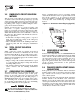
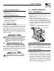
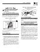
3.2 CONTROL CONSOLE
COMPONENTS
The components of a liquid-cooled generator control
console (Figure 3.1) are as follows:
Figure 3.1 - Liquid-Cooled Generator Panel
3.2.1 HOURMETER
Indicates time the engine-generator has operated, in
hours and tenths of hours. Use the hourmeter along
with the periodic maintenance schedule for the gen-
erator set.
3.2.2 AUTO/OFF/MANUAL SWITCH
Use this three-position switch as follows:
• Set the switch to AUTO for fully automatic opera-
tion. See “Automatic Operation”, Section 3.4.
• Set switch to MANUAL position to crank and start
the generator engine.
• Set switch to OFF position to shut down an oper-
ating engine. With OFF selected, operation will not
be possible.
With switch set to AUTO, engine can crank
and start suddenly without warning. Such
automatic start up normally occurs when utili-
ty source voltage drops below a pre-set level.
To prevent possible injury that might be
caused by such sudden starts, set
AUTO/OFF/MANUAL switch to OFF before
working on or around the unit. Then, place a
"DO NOT OPERATE" tag on control console.
3.2.3 FAULT INDICATOR LAMP
The lamp goes ON when one or more of the following
engine faults occurs and when engine shuts down.
• Low oil pressure • Overcrank
• High coolant temperature • Overspeed
• Low coolant level
3.2.4 15 AMP FUSE
The fuse protects the control console’s DC control
circuit against electrical overload. If the fuse has
melted open because of an overload, engine cranking
and startup cannot occur. If replacement of the fuse
is necessary, use only an identical 15-amp fuse. (Type
AGC, part number 022676).
3.2.5 7.5 AMP INLINE FUSE
This inline fuse is connected in the 15A line that runs
between the AUTO/OFF/MANUAL switch and position
10 of the 76009A PCB. This fuse protects the start,
fuel, field boost, and transfer outputs from the PCB
and will open if there is excessive current draw on
any one of these outputs.
NOTE:
This fuse will not remove the positive (+) battery
input power from the PCB when it opens. This
means the exercise timer will not be reset. If this
fuse does open, carefully check the wiring to the
start, fuel, field boost and transfer outputs before
replacing the fuse.
3.2.6 SET EXERCISE TIME SWITCH
This switch allows for programming the generator to
start and exercise automatically. See “Weekly
Exercise Cycle” (Section 3.5).
3.3 MANUAL TRANSFER AND
START-UP
To transfer electrical loads to the STANDBY (GEN-
ERATOR) power source side and start the engine
manually, refer to the Owner’s Manual of the particu-
lar transfer switch.
3.4 AUTOMATIC OPERATION
To set the system for fully automatic operation, pro-
ceed as follows:
• Check that load circuits are connected to the
utility power supply.
• Set the AUTO/OFF/MANUAL switch to its AUTO
position.
• Set the generator main circuit breaker to its ON or
CLOSED position.
3.5 WEEKLY EXERCISE CYCLE
The generator will start and exercise once every seven
days. During this weekly exercise, the unit runs for
about 20 minutes and shuts down. Transfer of loads
to generator output does not occur during the exer-
cise.
To select day and time for exercising, proceed as
follows:
!
DANGER
AUTO
MANUAL
OFF
FUSE
15-A
AGC
FAULT
INDICATOR
SET
EXERCISE
TIME
ON
HOUR METER
Section 3 - Operation
Guardian Liquid-cooled 15 kW, 20 kW and 25 kW Generators