Owner’s Manual Liquid-cooled, Prepackaged Standby Generators Model Numbers 004721-0, 004722-0, 004723-0, 004724-0, 004725-0, 004725-1, 004725-2, 004725-3, 004726-0 ! Not intended for use in critical life support applications. ! ONLY QUALIFIED ELECTRICIANS OR CONTRACTORS SHOULD ATTEMPT INSTALLATION!! DEADLY EXHAUST FUMES. OUTDOOR INSTALLATION ONLY! This manual should remain with the unit.
INTRODUCTION Thank you for purchasing this model of the standby generator set product line by Generac Power Systems. Every effort was expended to make sure that the information and instructions in this manual are both accurate and current at the time the manual was written. However, the manufacturer reserves the right to change, alter or otherwise improve this product(s) at any time without prior notice.
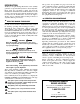
Table of Contents Guardian Liquid-cooled 15 kW, 20 kW and 25 kW Generators INTRODUCTION ..................................IFC SAFETY RULES ......................................2 Section 3 — OPERATION....................12 3.1 Using a Standard “GTS” Transfer Switch....12 3.2 Control Console Components......................13 Section 1 — GENERAL INFORMATION..................4 3.3 Manual Transfer and Startup ......................13 3.4 Automatic Operation ..................................13 1.
IMPORTANT SAFETY INSTRUCTIONS Guardian Liquid-cooled 15 kW, 20 kW and 25 kW Generators ! SAVE THESE INSTRUCTIONS – The manufacturer suggests that these rules for safe operation be copied and posted in potential hazard areas. Safety should be stressed to all operators, potential operators, and service and repair technicians for this equipment. ! SAVE THESE INSTRUCTIONS – This manual contains important instructions that should be followed during installation and maintenance of the generator and batteries.
IMPORTANT SAFETY INSTRUCTIONS Guardian Liquid-cooled 15 kW, 20 kW and 25 kW Generators • Inspect the generator regularly, and promptly repair or replace all worn, damaged or defective parts using only factory-approved parts. • Before performing any maintenance on the generator, disconnect its battery cables to prevent accidental start-up. Disconnect the cable from the battery post indicated by a NEGATIVE, NEG or (–) first. Reconnect that cable last. • Never use the generator or any of its parts as a step.
Section 1 - General Information Guardian Liquid-cooled 15 kW, 20 kW and 25 kW Generators 1.1 GENERATOR 1.3 AUTOMATIC SYSTEM OPERATION This equipment is a liquid-cooled, engine-driven generator set. The generator is designed to supply electrical power that operates critical electrical loads during utility power failure. The unit has been factory-installed in a weather resistant, all metal enclosure and is intended for outdoor installation only.
Section 1 - General Information Guardian Liquid-cooled 15 kW, 20 kW and 25 kW Generators Figure 1.2 - Main Circuit Breaker Model Rating Phase 004721/004722 004723/004724 004725/004726 15,000 20,000 25,000 1 1 1 Actual Current C/B Rating* 62.5 70 83.3 90 104.2 125 * Amp Rating of CB structured under model. Recommended fuels should have a Btu content of at least 1,000 Btus per cubic foot for natural gas and at least 2,520 Btus per cubic foot for LP gas.
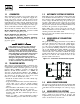
Section 1 — General Information Guardian Liquid-cooled 15 kW, 20 kW and 25 kW Generators • LED 2 is YELLOW. This LED is on when the circuit board battery charger is on. This LED will cycle on and off with the battery charger, 4.85 hours on the 4.85 hours off. • LED 3 is GREEN. This LED will flash when the circuit board has load voltage available to it. This LED will function when voltage is available across T1 and T2. Figure 1.6 - Low Coolant Level Sensor 1.7.
Section 1 — General Information Guardian Liquid-cooled 15 kW, 20 kW and 25 kW Generators NOTE: 1.10 SPECIFICATIONS 1.10.1 GENERATOR SPECIFICATIONS Single-Phase Model Rated Max. Cont. AC Power Output (kW) Rated voltage (volts) No. of Rotor Poles Driven Speed of Rotor Rotor Excitation System Type of Stator Rotor/Stator Insulation 004725 004723 004721 004726 004724 004722 25 20 15 120/240 2 4 3600 3600 1800 Direct excited brush type 4 Wire Class F 1.10.2 ENGINE SPECIFICATIONS Make..................
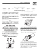
Section 2 — Installation Guardian Liquid-cooled 15 kW, 20 kW and 25 kW Generators NOTE: 1.16 BEFORE INSTALLATION Port 1 is for NG only and Port 2 is for LP vapor only. No provision for simultaneous fuels has been made. Before installing this equipment, check the ratings of both the generator and the transfer switch. Read “Emergency Isolation Method” and “Total Circuit Isolation Method” in Sections 2.5 and 2.6.
Section 2 — Installation Guardian Liquid-cooled 15 kW, 20 kW and 25 kW Generators 2.1.1 NFPA STANDARDS The following published standards booklets pertaining to standby electric systems are available form the National Fire Protection Association (NFPA), Batterymarch Park, Quincy, MA 02269: • NFPA No. 37, STATIONARY COMBUSTION ENGINES AND GAS TURBINES. • NFPA No. 76A, ESSENTIAL ELECTRICAL SYSTEMS FOR HEALTH CARE FACILITIES. • NFPA No. 220, STANDARD TYPES OF BUILDING CONSTRUCTION • NFPA No.
Section 2 — Installation Guardian Liquid-cooled 15 kW, 20 kW and 25 kW Generators 2.5 EMERGENCY CIRCUIT ISOLATION METHOD This prevents overloading the generator by keeping electrical loads below the wattage/amperage capacity of the generator. If the generator is powering only critical loads, within the wattage/amperage capacity, during utility power outages, consider using the emergency circuit isolation method.
Section 2 — Installation Guardian Liquid-cooled 15 kW, 20 kW and 25 kW Generators 2.10 BATTERY INSTALLATION DANGER ! Standby generators installed with automatic transfer switches will crank and start automatically when NORMAL (UTILITY) source voltage is removed or is below an acceptable preset level.
Section 3 — Operation Guardian Liquid-cooled 15 kW, 20 kW and 25 kW Generators Before starting the generator for the first time, the installer must complete the following procedures. For follow-up maintenance information and/or service intervals, please refer to Section 4, “Maintenance.” 2.11.2 TRANSFER SWITCH If this generator is used to supply power to any electrical system normally powered by an electric utility, the National Electrical Code requires that a transfer switch be installed.
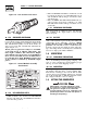
Section 3 - Operation Guardian Liquid-cooled 15 kW, 20 kW and 25 kW Generators 3.2 CONTROL CONSOLE COMPONENTS The components of a liquid-cooled generator control console (Figure 3.1) are as follows: Figure 3.1 - Liquid-Cooled Generator Panel 3.2.4 The fuse protects the control console’s DC control circuit against electrical overload. If the fuse has melted open because of an overload, engine cranking and startup cannot occur.
Section 4 — Maintenance Guardian Liquid-cooled 15 kW, 20 kW and 25 kW Generators • Set the AUTO/OFF/MANUAL switch to OFF. • Set generator main circuit breaker to OFF or OPEN. • Locate the rocker switch on the control panel identified with the words “Set Exercise Time” (Figure 3.2). • Push “Set Exercise Time” switch to ON position for 20 to 30 seconds and then release. Switch will spring back into its original position when released.
Section 4 — Maintenance Guardian Liquid-cooled 15 kW, 20 kW and 25 kW Generators E. EVERY 500 OPERATING HOURS 1.Service air cleaner. 2.Check starter. 3.Check engine DC alternator. F. EVERY 800 OPERATING HOURS 1.Retorque cylinder head. (See Torque Specs, Section 1.13.) 2.Retorque intake and exhaust manifold. (See Torque Specs, Section 1.13.) 3.Check engine compression. 4.Check valve clearance. 4.
Section 4 — Maintenance Guardian Liquid-cooled 15 kW, 20 kW and 25 kW Generators 4.5 MAINTENANCE OWNER/ OPERATOR CAN PERFORM 4.5.1 CHECK ENGINE OIL LEVEL Refer to “Checking Fluid Levels” in Section 4.4. 4.5.2 CHECK BATTERY • Check battery fluid level each week as outlined under “Check Fluid Levels”. • Check battery cables for condition, tightness, corrosion or damage. Clean, tighten or replace as necessary. 4.5.
Section 4 — Maintenance Guardian Liquid-cooled 15 kW, 20 kW and 25 kW Generators Figure 4.4 – Setting the Spark Plug Gap SET PLUG GAP AT 0.5-0.6 mm (0.020-0.025 inch) After refilling the crankcase with oil, always check oil level on dipstick. NEVER OPERATE ENGINE WITH OIL BELOW THE DIPSTICK “ADD” MARK. 7. Start engine and check for oil leaks. ! 4.5.
Section 4 — Maintenance Guardian Liquid-cooled 15 kW, 20 kW and 25 kW Generators 4.6.2 BATTERY All lead-acid storage batteries discharge when not in use. Refer to specific instructions and warnings that accompany the battery. If such information is not available, observe the following precautions when handling a battery: • DO NOT use jumper cables and a booster battery to crank or start the generator engine. • DO NOT recharge a weak battery while it is installed in the generator.
Section 4 — Maintenance Guardian Liquid-cooled 15 kW, 20 kW and 25 kW Generators 4.7 SCHEDULED MAINTENANCE The following is a recommended maintenance schedule for Generac Guardian small standby and residential generator sets. The established intervals in the schedule are the maximum recommended when the unit is used in an average service application. They will need to be decreased (performed more frequently) if the unit is used in a severe application.
Section 4 — Maintenance Guardian Liquid-cooled 15 kW, 20 kW and 25 kW Generators Maintenance Tasks Level 1 Recommended to be done monthly/ 10 hrs. 1. Disable the unit from operating per the first page warning. 2. Check the engine oil level. Adjust as necessary. 3. Check the engine coolant level. Adjust as necessary. 4. Check the engine coolant thermal protection level. Correct as necessary. 5. Check the natural gas delivery system on gas engine driven units. Tighten connections as necessary. 6.
Section 4 — Maintenance Guardian Liquid-cooled 15 kW, 20 kW and 25 kW Generators Maintenance Tasks Level 1 Recommended to be done monthly/ 10 hrs. Level 2 Task Comp. (DateInitials) Required to be done 3 months/ Break-in 30 hrs. Level 3 Task Comp. (DateInitials) Required to be done Semiannually/ 50 hrs. Level 4 Task Comp. (DateInitials) Required to be done Annually/ 100 hrs. Task Comp. (DateInitials) 13.
Section 5 — Troubleshooting Guardian Liquid-cooled 15 kW, 20 kW and 25 kW Generators 5.1 TROUBLESHOOTING POINTS PROBLEM CAUSE CORRECTION Engine won’t crank. 1. 15 amp fuse blown. 2. Loose or corroded or defective battery cables. 3. Defective starter contactor. 4. Defective starter motor. 5. Dead or Defective Battery. 1. Replace fuse. 2. Tighten, clean or replace battery cables as necessary. 3. Replace contactor. 4. Replace starter motor. 5. Remove, change or replace battery.
Section 6 — Notes Guardian Liquid-cooled 15 kW, 20 kW and 25 kW Generators Generac® Power Systems, Inc.
Section 6 — Notes Guardian Liquid-cooled 15 kW, 20 kW and 25 kW Generators 24 Generac® Power Systems, Inc.
Section 7 - Installation Diagram Guardian Liquid-cooled 15 kW, 20 kW and 25 kW Generators Drawing No. 0E1533-A Generac® Power Systems, Inc.
(BLACK) (BLACK) (BLUE) (RED) BLUE 178 225A 239 178 225 BLUE 0 225A 15A 178 239 183 4 TR1 YELLOW 8 F1 15C 15C BLUE 14 15 14 15 0 183 162 CB2 162 BLACK BLACK 15C 2 0 4 0 4 15E 6 14 AS - FO SW 23 194 0 S16 14 S16 94 23 85 TS2 CAP 0 0 0 13 14 13 4 229 14 229 S16 S15 SUPRESSION ASSEMBLY FUSE 15 AMPS 56 56 BLUE 85 85 85 TERMINAL STRIP 7 POS.
Section 8 - Electrical Data Guardian Liquid-cooled 15 kW, 20 kW and 25 kW Generators Wiring Diagram — 1.5L Engine — Drawing No. 0E0343-B Generac® Power Systems, Inc.
EC 28 Generac® Power Systems, Inc.
Section 8 - Electrical Data Guardian Liquid-cooled 15 kW, 20 kW and 25 kW Generators Electrical Schematic — 1.5L — Drawing No. 0A7182-C Generac® Power Systems, Inc.
Section 9 - Exploded Views and Parts Guardian Liquid-cooled 15 kW, 20 kW and 25 kW Generators Governor Assembly — Drawing No. 0E1331-B 5 4 3 ITEM (13) NEOPRENE COATING 2 1 14 6 7 10 WIRE HARNESS 15 12 9 7 16 "A" 17 TO "A" 10 7 CARBURETOR ARM (REF.) 6 INTAKE MANIFOLD (REF.) 11 ITEM 1 2 3 4 5 6 7 8 9 10 11 12 13 14 15 16 17 18 PART NO. 098290 098941A 098958A 098942A 098225 043146 022097 084543A 098783 037398 0E1326 0A7106 074031 029333A 022507 022473 064526 0E1694 QTY.
Section 9 - Exploded Views and Parts Guardian Liquid-cooled 15 kW, 20 kW and 25 kW Generators Mounting Base — Drawing No. 0E0768-B 8 7 6 14 5 13 7 6 4 9 15 6 10 15 20 5 7 6 11 17 18 16 2 3 9 10 22 1 15 20 22 ITEM 1 2 3 4 5 6 7 8 9 10 11 13 14 15 16 17 18 19 20 21 22 PART NO. 0D8656 027482 070936 070936C 039253 022145 022129 045771 071956 051730 021991 0D9335 0D9336 0C2454 047411 022097 022473 055414 049813 026850 0A1694 QTY.
Section 9 - Exploded Views and Parts Guardian Liquid-cooled 15 kW and 20 kW Generators Standard Compartment — Drawing No. 0E0771-F 21 21 31 WELD STUD UNDER ROOF PANEL FOR ACCESS COVER CABLE 30 1 11 28 13 14 4 16 11 2 15 "Y" 26 10 29 22 23 20 26 17 18 11 15 8 24 19 4 5 9 11 26 17 10 6 18 25 2 24 3 17 10 25 5 7 24 11 32 Generac® Power Systems, Inc. NOTE: USE DOOR LATCH FASTENER TO SECURE GROUND WIRE. NOTE: USE LOCTITE ON NUTS ITEM #26.
Section 9 - Exploded Views and Parts Guardian Liquid-cooled 15 kW and 20 kW Generators Standard Compartment — Drawing No. 0E0771-F ITEM 1 2 3 4 5 6 7 8 9 10 11 12 13 14 15 16 17 18 19 20 21 22 23 24 25 26 27 28 29 30 * 31 * PART NO. 0D8666 0D8664C 0D8657 0D8660 0A7568 0D8659 0D8662 0D8661 0D8658 067042 0C2454 033530 051716 022152 0912970064 023762 0912970063 022264 067035 022127 0C2634A 022473 022097 0D2023 0F3390 037337 0D2023 0D8664A 0D8664B 0F1563 0C2634 QTY.
9 43 34 Generac® Power Systems, Inc. 38 8 4 39 7 33 11 42 19 6 12 3 34 22 3 35 10 36 11 24 5 13 14 4 10 "Y" "Y" 15 11 26 18 17 21 1 11 17 5 15 34 49 50 29 31 10 42 24 22 23 21 3 11 40 11 28 4 48 25 30 2 20 STATES FOAM IS ON FAR SIDE STATES FOAM IS ON NEAR SIDE 11 NOTE: USE DOOR LATCH 17 NOTE: USE LOCTITE ON NUT #037337. TYPICAL OF FRONT DUCT & ROOF PANEL. SECURE AS SHOWN.
Section 9 - Exploded Views and Parts Guardian Liquid-cooled 25 kW Generators Acoustic Compartment — Drawing No. 0E0772-H ITEM 1 2 3 4 5 6 7 8 9 10 11 12 13 14 15 16 17 18 19 20 21 22 23 24 25 26 27 28 29 30 31 32 33 34 35 36 37 38 39 40 41 42 43 45 46 47 48 49 * 50 * PART NO.
Section 9 - Exploded Views and Parts 39 32 27 25 26 33 6 10 7 8 58 31 5 55 54 9 53 52 3 TO 'A' 50 34 42 38 39 49 40 41 12 28 11 2 30 31 36 Generac® Power Systems, Inc. 57 17 28 18 28 26 16 51 13 29 38 A 23 39 24 'A' 40 41 21 28 14 56 22 35 20 1 28 43 15 45 46 44 47 32 37 36 40 41 48 4 Guardian Liquid-cooled 15 kW, 20 kW and 25 kW Generators Control Panel — Drawing No.
Section 9 - Exploded Views and Parts Guardian Liquid-cooled 15 kW, 20 kW and 25 kW Generators Control Panel — Drawing No. 0E0778-G ITEM PART NO. QTY.
38 Generac® Power Systems, Inc.
Section 9 - Exploded Views and Parts Guardian Liquid-cooled 15 kW, 20 kW and 25 kW Generators Engine — Drawing No. 0E1228-H ITEM PART NO. QTY.
28 22 40 Generac® Power Systems, Inc. 32 28 "A" 30 29 (BOTTOM ONLY) 1 10 2 21 9 32 31 23 26 35 10 8 8 8 8 3 14 12 12 24 18 TO THERMOSTAT ADAPTER 14 WATER INLET TUBE (ON BLOCK) 19 20 7 33 34 TO WATER INLET (MIDWAY UP ENGINE BLOCK) 7 16 7 TO ENGINE BYPASS 4 15 17 6 13 17 14 11 34 33 12 11 Section 9 - Exploded Views and Parts Guardian Liquid-cooled 15 kW, 20 kW and 25 kW Generators Radiator — Drawing No.
Section 9 - Exploded Views and Parts Guardian Liquid-cooled 15 kW, 20 kW and 25 kW Generators Radiator — Drawing No. 0E0769-J ITEM 1 2 3 4* 5 6 7 8 9 10 11 12 13 14 15 16 17 * 18 19 20 21 22 23 24 26 27 28 29 30 31 32 33 34 35 PART NO. 0D8657 0A5734 0A6237 0A6238 084918 051520N 048031C 099502 083709 052250 047411 022097 049813 022473 084427 051520Z 058443 056892 0A6284 0A6258 029032 031669 060035 022127 046627 0C7649 0C2454 076749 0E0726 035461 0A7275 0A2111 065852 047290A QTY.
Section 9 - Exploded Views and Parts Guardian Liquid-cooled 15 kW, 20 kW and 25 kW Generators Fuel System — Drawing No. 0E0774-F 18 13 8 21 24 25 22 17 "C" 16 29 "C" 14 30 12 34 31 36 37 35 32 33 38 39 19 40 1 26 20 6 28 PORT "OUT 1" (NATURAL GAS) 41 6 11 43 9 1 10 42 "D" 23 40 41 PORT "OUT 2" 6 2 3 15 11 4 L.P. VAPOR 42 Generac® Power Systems, Inc.
Section 9 - Exploded Views and Parts Guardian Liquid-cooled 15 kW, 20 kW and 25 kW Generators Fuel System — Drawing No. 0E0774-F ITEM PART NO.
Section 9 - Exploded Views and Parts 14 15 18 9 To Blower Housing 8 36 32 24 1 23 35 17 7 13 16 29 28 22 1 30 21 3 31 12 21 20 19 6 5 4 26 To Engine Crankshaft Guardian Liquid-cooled 15 kW, 20 kW and 25 kW Generators Alternator — Drawing No. 0A9348-G 44 Generac® Power Systems, Inc.
Section 9 - Exploded Views and Parts Guardian Liquid-cooled 15 kW, 20 kW and 25 kW Generators Alternator — Drawing No. 0A9348-G ITEM 1 2 3 4 5 6 7 8 9 10 11 12 13 14 15 16 17 18 19 20 21 22 23 24 26 * 27 28 29 30 31 32 33 35 36 PART NO.
Section 9 - Exploded Views and Parts Guardian Liquid-cooled 15 kW, 20 kW and 25 kW Generators Battery — Drawing No. 0E0770-B 2 STARTER SOLENOID 8 13 4 14 8 3 1 TO ENGINE BLOCK 16 6 5 7 9 15 ITEM 1 2 3 4 5 6 7 8 9 13 14 15 16 17 PART NO. 077483 038804D 038805B 0742600131 022131 046526 052213 075763 0D8668 050331A 050331 0C2454 025507 027482 QTY. REF 1 1 1 1 1 1 3 1 1 1 2 1 2 DESCRIPTION BATT 12VDC 75-AH 26 (NOT INCLUDED) CABLE BATT RED #4 X 20.00 CABLE BATT BLK #4 X 23.00 ASSY,WIRE#16 RED 1.
Section 9 - Exploded Views and Parts Guardian Liquid-cooled 15 kW, 20 kW and 25 kW Generators Muffler — Drawing No. 0E0773-A 10 9 14 8 15 6 12 13 9 3 7 3 5 4 3 2 ITEM 1 2 3 4 5 6 7 8 9 10 11 12 13 14 15 PART NO. 0A4355 0E2844 036434 036449 0E0109 0C1318 0D8657 0E0170 0D9437 060366 039253 022145 022129 045771 0A8974 027837 QTY. 1 1 3 3 1 1 1 1 1 2 4 4 4 4 1 2 DESCRIPTION MANIFOLD EXHAUST 1.5L NIPPLE TOE 1.5NPTX5.5 BLK IRON BOLT U 5/16-18 X 2.09 SADDLE 2 INCH PIPE,EXHAUST 1.
Section 10 – Warranty Guardian Liquid-cooled 15 kW, 20 kW and 25 kW Generators CALIFORNIA EMISSION CONTROL WARRANTY STATEMENT YOUR WARRANTY RIGHTS AND OBLIGATIONS The California Air Resources Board (CARB) and Generac Power Systems, Inc. (Generac) are pleased to explain the Emission Control System Warranty on your new engine.* In California, new utility, and lawn and garden equipment engines must be designed, built and equipped to meet the state’s stringent anti-smog standards.
Section 10 – Warranty Guardian Liquid-cooled 15 kW, 20 kW and 25 kW Generators EMISSION CONTROL SYSTEM WARRANTY Emission Control System Warranty (ECS Warranty) for 1995 and later model year engines: (a) Applicability: This warranty shall apply to 1995 and later model year engines. The ECS Warranty Period shall begin on the date the new engine or equipment is purchased by/delivered to its original, end-use purchaser/owner and shall continue for 24 consecutive months thereafter.
Section 10 – Warranty Guardian Liquid-cooled 15 kW, 20 kW and 25 kW Generators GENERAC POWER SYSTEMS "TWO YEAR" LIMITED WARRANTY FOR GUARDIAN® "PREPACKAGED EMERGENCY AUTOMATIC STANDBY GENERATORS" For a period of two years from the date of original sale, Generac Power Systems, Inc. (Generac) warrants that its Guardian generator will be free from defects in material and workmanship for the items and period set forth below.