Installation and Owner’s Manual 7, 10, 13 and 16kW Air-cooled, Automatic Standby Generators US C LISTED Models: 005240, 005280 (6 kW NG, 7 kW LP) 005241, 005281 (9 kW NG, 10 kW LP) 005242, 005282 (13 kW NG, 13 kW LP) 005243, 005244, (15 kW NG, 16 kW LP) 005283, 005284 GENERAC R POWER SYSTEMS, INC. R Not intended for use as Primary Power in place of utility or in life-support applications. DANGER DEADLY EXHAUST FUMES.
INTRODUCTION Thank you for purchasing this model of the Guardian product line by Generac Power Systems Inc. This model is a compact, high performance, air-cooled, engine-driven generator designed to automatically supply electrical power to operate critical loads during a utility power failure. This unit is factory installed in an all-weather, metal enclosure that is intended exclusively for outdoor installation.
Table of Contents Air-cooled Generators Introduction ........................Inside Front Cover Read This Manual Thoroughly ........................ IFC Contents .......................................................... IFC Operation and Maintenance ............................ IFC How to Obtain Service..................................... IFC Authorized Dealer Locator Number ................... IFC Safety Rules ........................................................2 Standards Index ...................
IMPORTANT SAFETY INSTRUCTIONS Air-cooled Generators SAVE THESE INSTRUCTIONS – The manufacturer suggests that these rules for safe operation be copied and posted near the unit’s installation site. Safety should be stressed to all operators and potential operators of this equipment. • WARNING: • The engine exhaust from this product contains chemicals known to the state of California to cause cancer, birth defects or other reproductive harm.
IMPORTANT SAFETY INSTRUCTIONS Air-cooled Generators ELECTRICAL HAZARDS • All generators covered by this manual produce dangerous electrical voltages and can cause fatal electrical shock. Utility power delivers extremely high and dangerous voltages to the transfer switch as does the standby generator when it is in operation. Avoid contact with bare wires, terminals, connections, etc., while the unit is running.
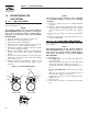
Section 1 — General Information Air-cooled Generators DANGER qualified electricians or contractors should Only attempt such installations, which must comply strictly with applicable codes, standards and regulations. 1.1 UNPACKING/INSPECTION After unpacking, carefully inspect the contents for damage. • This standby generator set is ready for installation with a factory supplied and pre-mounted base pad and has a weather protective enclosure that is intended for outdoor installation only.
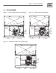
Section 1 — General Information Air-cooled Generators 1.4 THE GENERATOR Figure 1.1 – 7kW, Single Cylinder GH-410 Engine Figure 1.2 – 10kW, V-twin GT-530 Engine Control Panel Oil Dipstick Data Decal Oil Dipstick Air Filter Cover Data Decal Control Panel Exhaust Enclosure Exhaust Enclosure Air Filter Fuel Inlet (Back) Fuel Inlet (Back) Fuel Regulator Composite Base Oil Filter Fuel Regulator Composite Base Battery Compartment Oil Filter Battery Compartment Figure 1.
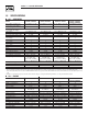
Section 1 — General Information Air-cooled Generators 1.5 SPECIFICATIONS 1.5.1 GENERATOR Model Rated Max. Continuous Power Capacity (Watts*) Rated Voltage Rated Max.
Section 1 — General Information Air-cooled Generators 1.6 SYSTEM SET LED The “System Set” LED is lit when all of the following conditions are true: 1. The AUTO/OFF/MANUAL switch is set to the AUTO position. 2. The utility voltage being supplied to the unit is being sensed by the PCB. If the utility sense voltage is not connected to the unit or if it is below approximately 150-160 volts AC, then the system set light will flash rapidly.
Section 1 — General Information Air-cooled Generators 1.9 RECONFIGURING THE FUEL SYSTEM NOTE: Use an approved pipe sealant or joint compound on all threaded fittings to reduce the possibility of leakage. 1.9.1 7 KW, 410CC ENGINE To reconfigure the fuel system from NG to LP, follow these steps (Figure 1.4): NOTE: The primary regulator for the propane supply is NOT INCLUDED with the generator. A fuel pressure of 10 to 12 inches of water column (0.36 to 0.
Section 1 — General Information Air-cooled Generators Figure 1.5 - 10kW, GT-530 (Inlet Hose Slid Back) Figure 1.8 - 13/16kW, GT-990 (Airbox Cover Removed) Fuel Selection Lever - "Out" Position for Liquid Propane (Vapor) Fuel Fuel Selection Lever - "In" Position for Natural Gas Fuel Figure 1.6 - 10kW, GT-530 (Inlet Hose Slid Back) 1.10 LOCATION 1.10.1 GENERATOR Fuel Selection Lever - "Out" Position for Liquid Propane (Vapor) Fuel Figure 1.
Section 1 — General Information Air-cooled Generators • Install the generator as close as possible to the fuel supply, to reduce the length of piping. • Install the generator as close as possible to the transfer switch. REMEMBER THAT LAWS OR CODES MAY REGULATE THE DISTANCE AND LOCATION. • The genset must be installed on a level surface. The base frame must be level within two (2) inches all around. • The generator is typically placed on pea gravel or crushed stone.
Section 1 — General Information Air-cooled Generators Figure 1.10 – Battery Cable Connections not open or mutilate the battery. Released Do electrolyte has been known to be harmful to the skin and eyes, and to be toxic. electrolyte is a dilute sulfuric acid that is The harmful to the skin and eyes. It is electrically conductive and corrosive.
Section 2 — Post Installation Start-up and Adjustments Air-cooled Generators 2.1 BEFORE INITIAL START-UP DANGER NOTE: These units have been run and tested at the factory prior to being shipped and do not require any type of break-in. Before starting, complete the following: 1. Set the generator’s main circuit breaker to its OFF (or OPEN) position. 2. Set the generator's AUTO/OFF/MANUAL switch to the OFF position. 3. Turn OFF all breakers on the load center of the transfer box (T1 and T2). 4.
Section 2 — Post Installation Start-up and Adjustments Air-cooled Generators 2.4 GENERATOR TESTS UNDER LOAD To test the generator set with electrical loads applied, proceed as follows: 1. Set generator’s main circuit breaker to its OFF (or OPEN) position. 2. Turn OFF all breakers on the load center of the transfer box (T1 and T2). 3. Set the generator's AUTO/OFF/MANUAL switch to OFF. 4.
Section 2 — Post Installation Start-up and Adjustments Air-cooled Generators 1. Turn off utility power to the main distribution panel in the house. This can be done by switching the service main breaker to the off or open position. 2. Allow the generator to start. Before loading the generator, confirm that the No Load Frequency, with the roof open and door off, is set to 63-63.5 Hz. Transfer load to emergency circuits. 3. Turn on appliances, lights, pumps, etc.
Section 3 — Operation Air-cooled Generators 4. Connect a frequency meter across the generators AC output leads. 5. Turn the primary adjust screw to obtain a frequency reading of 61.5 Hertz. Turn the secondary adjust screw to obtain a frequency of 62.5 Hz. 6. When frequency is correct at no load, check the AC voltage reading. If voltage is incorrect, the voltage regulator may require adjustment (See the Voltage Regulator Adjustment section). 2.7.
Section 3 — Operation Air-cooled Generators 3.1.4 CHOKE OPERATION 1. 990 engines have an electric choke in the air box that is automatically controlled by the electronic control board. 2. 530 engines have an electric choke on the divider panel air inlet hose that is automatically controlled by the electronic control board. 3. 410 engines do not have a choke. 3.2 AUTOMATIC TRANSFER OPERATION To select automatic operation, do the following: 1.
Section 3 — Operation Air-cooled Generators 4. Use the manual transfer handle inside the transfer switch to move the main contacts to their STANDBY position, i.e., loads connected to the standby power source (Figure 3.2). 5. To crank and start the engine, set the AUTO/OFF/ MANUAL switch to MANUAL. 6. Let the engine stabilize and warm up for a few minutes. 7. Set the generator’s main circuit breaker to its ON (or CLOSED) position. The standby power source now powers the loads. Figure 3.
Section 3 — Operation Air-cooled Generators Low speed exercise will be handled as follows: 3.6.3 OVERCRANK 1. The standard start sequence will be initiated. 2. The unit will run at 2,400 RPM. 3. If utility is lost during exercise, the controller will do the following: • Wait 10 seconds for utility to return. • If utility returns within 10 seconds, continue to exercise at 2,400 RPM. • If utility is still lost after 10 seconds, run the engine up to 3600 RPM and transfer the load.
Section 4 — Maintenance Air-cooled Generators 3.6.5 RPM SENSOR FAILURE 4.2 During cranking, if the board does not see a valid RPM signal within three (3) seconds, it will shut down and latch out on RPM sensor loss. During running, if the RPM signal is lost for one full second the board will shut down the engine, wait 15 seconds, then re-crank the engine.
Section 4 — Maintenance Air-cooled Generators Figure 4.3 — Oil Dipstick and Fill, 10kW 4.3.3 OIL & OIL FILTER CHANGE PROCEDURE To change the oil, proceed as follows: Oil Dipstick 1. Start the engine by moving the AUTO/OFF/ MANUAL switch to MANUAL and run until it is thoroughly warmed up. Then shut OFF the engine by moving the switch to the OFF position. 2. Immediately after the engine shuts OFF, pull the oil drain hose (Figure 4.5) free of its retaining clip.
Section 4 — Maintenance Air-cooled Generators 4.4 CHANGING THE ENGINE AIR CLEANER Figure 4.7 — 10kW Engine Air Cleaner 4.4.1 7, 13, AND 16KW GENERATORS Control Panel See Figures 1.1 and 1.2, for the location of the air cleaner. Use the following procedures (Figure 4.6, 7kW; Figure 4.8, 13/16kW): 1. 2. 3. 4. Lift the roof and remove the door. Turn the two screws counterclockwise to loosen. Remove the cover and air filter. Wipe away dust or debris from inside of the air box and around edges. 5.
Section 4 — Maintenance Air-cooled Generators 3. Check the spark plug gap using a wire feeler gauge. Adjust the gap to 0.76 mm (0.030 inch) for 7 and 10kW; and 1.02 mm (0.040 inch) for 13/16 kW by carefully bending the ground electrode (Figure 4.9). Figure 4.9 – Setting the Spark Plug Gap SET PLUG GAP AT 0.76 mm (.030 inch) - 7 & 10kW; 1.02 mm (.040 inch) - 13 & 16kW electrolyte is a dilute sulfuric acid that is The harmful to the skin and eyes. It is electrically • • • • 4.
Section 4 — Maintenance Air-cooled Generators • Remove spark plug wires and position wires away from plugs. • Remove spark plugs. • Make sure the piston is at Top Dead Center (TDC) of its compression stroke (both valves closed). To get the piston at TDC, remove the intake screen at the front of the engine to gain access to the flywheel nut. Use a large socket and socket wrench to rotate the nut and hence the engine in a clockwise direction. While watching the piston through the spark plug hole.
Section 4 — Maintenance Air-cooled Generators 4.10 CORROSION PROTECTION 4.11.2 RETURN TO SERVICE Periodically wash and wax the enclosure using automotive type products. Frequent washing is recommended in salt water/coastal areas. Spray engine linkages with a light oil such as WD-40. To return the unit to service after storage, proceed as follows: 4.11 OUT OF SERVICE PROCEDURE 4.11.
Section 4 — Maintenance Air-cooled Generators 4.12 SERVICE SCHEDULE ATTENTION: It is recommended that all service work be performed by the nearest Authorized Dealer. SYSTEM/COMPONENT X = Action R = Replace as Necessary * = Notify Dealer if Repair is Needed.
Section 5 — Troubleshooting Air-cooled Generators 5.1 TROUBLESHOOTING GUIDE Problem Cause Correction The engine will not crank. 1. Fuse blown. 1. Correct short circuit condition, replace 15A fuse in generator control panel. 2. Tighten, clean or replace as necessary. 3. * 4. * 5. Charge or replace battery. 2. Loose, corroded or defective battery cables. 3. Defective starter contactor. (7 kW) 4. Defective starter motor. 5. Dead Battery. The engine cranks but will not start.
Section 6 — Notes Air-cooled Generators 27
Section 6 — Notes Air-cooled Generators 28
Section 6 — Notes Air-cooled Generators 29
Section 7 — Mounting Dimensions Air-cooled Generators Drawing No.
Section 8 — Electrical Data Air-cooled Generators Electrical Schematic – 8, 10, 12 and 16 Circuit Load Center – Drawing No.
Section 8 — Electrical Data Air-cooled Generators Wiring Diagram – 10, 13 & 16kW, V-Twin – Drawing No.
Section 8 — Electrical Data Air-cooled Generators Wiring Diagram – 10, 13 & 16kW, V-Twin – Drawing No.
Section 8 — Electrical Data Air-cooled Generators Electrical Schematic – 10, 13 & 16kW, V-Twin – Drawing No.
Section 8 — Electrical Data Air-cooled Generators Electrical Schematic – 10, 13 & 16kW, V-Twin – Drawing No. 0F7823 ENGINE AND ALTERNATOR IM2 BATTERY CHARGE WINDING SP2 66 18 IM1 77 SP1 86 85 STATOR 6 LOP 2 DPE WINDING HTO POWER WINDING 11 44 22 POWER WINDING 33 0 0 6 BA 2 4 4 SC 16 0 BATTERY 12V 2 16 FIELD RED 13 13 6 16 14 66 0 FS1 FS2 0 0 SM SC 77 0 0 0 0 0 0 0 0 0 11 11 11 22 22 22 33 33 22 LC1 LC1 LC2 LC2 44 11 I.C.T.
Section 8 — Electrical Data Air-cooled Generators Wiring Diagram – 7kW, Single Cylinder – Drawing No.
Section 8 — Electrical Data Air-cooled Generators Wiring Diagram – 7kW, Single Cylinder – Drawing No.
Section 8 — Electrical Data Air-cooled Generators Electrical Schematic – 7kW, Single Cylinder – Drawing No.
Section 8 — Electrical Data Air-cooled Generators Electrical Schematic – 7kW, Single Cylinder – Drawing No.
Section 8 — Electrical Data Air-cooled Generators Wiring Diagram – 8, 10, 12 and 16 Circuit Load Center – Drawing No.
Section 8 — Electrical Data Air-cooled Generators Wiring Diagram – 8, 10, 12 and 16 Circuit Load Center – Drawing No.
Section 9 — Exploded Views and Parts Lists Air-cooled Generators Enclosure – Drawing No. 0F9431-B SHEET METAL PAINT/MATERIAL CODE LEGEND The following exploded views contain part numbers of various sheet metal components. Only the base part number is listed. When ordering sheet metal, the correct color and material information must be included as a suffix at the end of the part number as shown below. Material Color Example: Desc. Part No.
Section 9 — Exploded Views and Parts Lists Air-cooled Generators Enclosure – Drawing No. 0F9431-B ITEM PART NO. QTY.
44 37 8,9 22 17 10 3 27 29 27 7 6 26 20 44 43 39 32 2 28 17 4 25 23 13 18 16 17 14 13 17 40 12 33 15 21 24 44 31 35 38 34 5 15 25 23 32 44 15 36 43 42 30 1 41 11 29 19 31 32 44 Section 9 — Exploded Views and Parts Lists Air-cooled Generators Control Panel – Drawing No.
Section 9 — Exploded Views and Parts Lists Air-cooled Generators Control Panel – Drawing No. 0F9695-B ITEM 1 2 3 4 5 6 7 8 9 10 11 12 13 14 15 16 17 18 19 20 21 22 23 24 25 26 27 28 29 30 31 32 33 34 35 36 37 38 39 40 41 42 43 44 PART NO.
Section 9 — Exploded Views and Parts Lists Air-cooled Generators Transfer Switch Assembly – Drawing No.
Section 9 — Exploded Views and Parts Lists Air-cooled Generators Transfer Switch Assembly – Drawing No. 0F9774-A ITEM PART NO. QTY. DESCRIPTION 1 2 3 0F8278 0D4800 0F5211 0D3092 0F8312 0C2237 1 1 1 1 1 1 3A 3B 3C 3D 077220 077220A 082574 084464 1 1 1 1 4 5 6 7 8 074908 024912 0A1658 063617 0E7889A 0E7889 6 1 1 1 1 1 0F9213 0A1495 0A1661 022473 081108 0F9199 0D4684 0D4684A 0F8279 0F4790 022152 064526 0E6155 063378 0G0979 1 4 2 1 1 1 1 1 1 10.
Section 9 — Exploded Views and Parts Lists Air-cooled Generators 13 & 16kW, GT-990 Engine – Drawing No.
Section 9 — Exploded Views and Parts Lists Air-cooled Generators 13 & 16kW, GT-990 Engine – Drawing No. 0F9430-C - Part 1 ITEM PART NO. QTY.
Section 9 — Exploded Views and Parts Lists Air-cooled Generators 13 & 16kW, GT-990 Engine – Drawing No.
Section 9 — Exploded Views and Parts Lists Air-cooled Generators 13 & 16kW, GT-990 Engine – Drawing No. 0F9430-C - Part 2 ITEM PART NO. QTY.
Section 9 — Exploded Views and Parts Lists Air-cooled Generators 10kW, GT-530 Engine – Drawing No.
Section 9 — Exploded Views and Parts Lists Air-cooled Generators 10kW, GT-530 Engine – Drawing No. 0F9429-c - Part 1 ITEM 1 2 3 4 5 6 7 8 9 10 11 12 13 14 15 16 17 18 19 20 21 22 23 24 25 26 27 28 29 30 31 32 33 34 35 36 37 38 39 40 41 42 43 44 45 46 47 48 49 50 51 52 53 54 55 56 57 PART NO.
Section 9 — Exploded Views and Parts Lists Air-cooled Generators 10kW, GT-530 Engine – Drawing No.
Section 9 — Exploded Views and Parts Lists Air-cooled Generators 10kW, GT-530 Engine – Drawing No. 0F9429-C - Part 2 ITEM PART NO. QTY.
Section 9 — Exploded Views and Parts Lists 42 17 50 31 25 28 27 37 24 35 36 23 33 45 43 39 19 18 20 34 46 44 11 32 22 48 47 26 41 38 29 30 25 12 40 51 21 13 14 15 53 49 1 6 54 16 52 1 2 5 10 4 3 7 11 8 9 Air-cooled Generators 7kW, GN-410 Engine – Drawing No.
Section 9 — Exploded Views and Parts Lists Air-cooled Generators 7kW, GN-410 Engine – Drawing No. 0F9428 - Part 1 ITEM 1 2 3 4 5 6 7 8 9 10 11 12 13 14 15 16 17 18 19 20 21 22 23 24 25 26 27 28 29 30 31 32 33 34 35 36 37 38 39 40 41 42 43 44 45 46 47 48 49 50 51 52 53 54 PART NO.
Section 9 — Exploded Views and Parts Lists 35 26 25 27 32 31 29 23 22 58 6 12 7 19 6 20 6 41 43 45 21 40 3 39 5 38 6 28 14 16 15 17 18 13 8 46 47 44 50 24 49 30 6 10 51 9 11 52 42 48 10 1 34 18 18 34 33 2 36 37 4 6 Air-cooled Generators 7kW, GN-410 Engine – Drawing No.
Section 9 — Exploded Views and Parts Lists Air-cooled Generators 7kW, GN-410 Engine – Drawing No. 0F9428 - Part 2 ITEM 1 2 3 4 5 6 7 8 9 10 11 12 13 14 15 16 17 18 19 20 21 22 23 24 25 26 27 28 29 30 31 32 33 34 35 36 37 38 39 40 41 42 43 44 45 46 47 48 49 50 51 52 PART NO.
Section 9 — Exploded Views and Parts Lists Air-cooled Generators 7kW, GN-410 Engine – Drawing No.
Section 9 — Exploded Views and Parts Lists Air-cooled Generators 7kW, GN-410 Engine – Drawing No. 0F9422-B ITEM 1 2 3 4 5 6 7 9 10 11 12 13 14 15 16 17 18 19 20 21 22 23 24 25 26 27 28 29 30 31 32 33 34 35 36 37 38 39 40 41 42 43 44 45 46 47 48 49 50 52 53 54 55 56 57 58 59 PART NO. QTY.
Section 9 — Exploded Views and Parts Lists Air-cooled Generators 10, 13, and 16kW, V-twin Generators – Drawing No.
Section 9 — Exploded Views and Parts Lists Air-cooled Generators 10, 13, and 16kW, V-twin Generators – Drawing No. 0F9423-C ITEM PART NO. QTY.
Section 9 — Exploded Views and Parts Lists 21 23 22 19 13 29 20 21 64 10 25 24 23 22 19 17 36 34 35 10 37 36 27 5 37 3 33 4 2 6 7 32 8 18 26 17 15 14 1 13 26 16 15 14 31 16 9 30 10 7KW 29 18 24 11 25 12 20 28 Air-cooled Generators 7 & 10kW, GN-410/GT-530 Regulator – Drawing No.
Section 9 — Exploded Views and Parts Lists Air-cooled Generators 7 & 10kW, GN-410/GT-530 Regulator – Drawing No. 0F9425 ITEM 1 2 3 4 5 6 7 8 9 10 11 12 13 14 15 16 17 18 19 20 21 22 23 24 25 26 27 28 29 30 31 32 33 34 35 36 37 PART NO.
Section 9 — Exploded Views and Parts Lists 3 28 30 66 34 35 7 6 33 3 2 4 9 8 32 27 5 12 31 11 6 7 8 10 17 1 26 15 14 27 13 16 19 22 23 29 18 24 25 21 20 Air-cooled Generators 13 & 16kW, GT-990 Regulator – Drawing No.
Section 9 — Exploded Views and Parts Lists Air-cooled Generators 13 & 16kW, GT-990 Regulator – Drawing No. 0F9426 ITEM 1 2 3 4 5 6 7 8 9 10 11 12 13 14 15 16 17 18 19 20 21 22 23 24 25 26 27 28 29 30 31 32 33 34 35 PART NO. 0F9285 0F5022 0C4647 0D4166 0F8096 022145 022129 0F4795 045771 0C6606 042907 026915A 0C5761 0C5968 0C6066 0C5759 0C5764 070728 0C6069 0F9189 045764 0C6731 0C6067 0C4706 0C6068 0C4643A 072683A 049226 0D3308 051713 0F8979 051716 0E9533 0E9534 0E9535 QTY.
Section 10 – Warranty Air-cooled Generators NOTE: This Emission Control Warranty Statement pertains to this product only IF the generator size is 15 kW or below. CALIFORNIA EMISSION CONTROL WARRANTY STATEMENT YOUR WARRANTY RIGHTS AND OBLIGATIONS The California Air Resources Board (CARB) and Generac Power Systems, Inc. (Generac) are pleased to explain the Emission Control System Warranty on your new engine.
Section 10 – Warranty Air-cooled Generators EMISSION CONTROL SYSTEM WARRANTY Emission Control System Warranty (ECS Warranty) for 1995 and later model year engines: (a) Applicability: This warranty shall apply to 1995 and later model year engines. The ECS Warranty Period shall begin on the date the new engine or equipment is purchased by/delivered to its original, end-use purchaser/owner and shall continue for 24 consecutive months thereafter.
Section 10 – Warranty Air-cooled Generators GENERAC POWER SYSTEMS "TWO YEAR" LIMITED WARRANTY FOR GUARDIAN® "PREPACKAGED EMERGENCY AUTOMATIC STANDBY GENERATORS" For a period of two years from the date of original sale, Generac Power Systems, Inc. (Generac) warrants that its Guardian generator will be free from defects in material and workmanship for the items and period set forth below.