Installation and Owner’s Manual Air-cooled Automatic Standby Generators Models: 04758-2 (6 kW NG, 7 kW LP) 04759-2 (12 kW NG, 12 kW LP) 04760-2 (13 kW NG, 15 kW LP) GENERAC R POWER SYSTEMS, INC. R *This manual should remain with the unit.* Not intended for use as Primary Power in place of utility or in life-support applications. DANGER DEADLY EXHAUST FUMES.
INTRODUCTION Thank you for purchasing this Guardian model by Generac Power Systems Inc.. This model is a compact, high performance, air-cooled, engine-driven generator designed to automatically supply electrical power to operate critical loads during a utility power failure. This unit is factory installed in an all-weather, metal enclosure that is intended exclusively for outdoor installation. This generator will operate using either vapor withdrawn liquid propane (LP) or natural gas (NG).
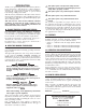
Table of Contents Air-cooled 7 kW, 12 kW and 15 kW Generators Introduction ........................Inside Front Cover 3.2.2 “Off” Position.................................... 14 Read This Manual Thoroughly ........................ IFC Contents .......................................................... IFC Operation and Maintenance ............................ IFC How to Obtain Service..................................... IFC Authorized Dealer Locator Number ................... IFC 3.2.
IMPORTANT SAFETY INSTRUCTIONS Air-cooled 7 kW, 12 kW and 15 kW Generators SAVE THESE INSTRUCTIONS – The manufacturer suggests that these rules for safe operation be copied and posted near the unit’s installation site. Safety should be stressed to all operators and potential operators of this equipment. WARNING: The engine exhaust from this product contains chemicals known to the state of California to cause cancer, birth defects or other reproductive harm.
IMPORTANT SAFETY INSTRUCTIONS Air-cooled 7 kW, 12 kW and 15 kW Generators ELECTRICAL HAZARDS • All generators covered by this manual produce dangerous electrical voltages and can cause fatal electrical shock. Utility power delivers extremely high and dangerous voltages to the transfer switch as does the standby generator when it is in operation. Avoid contact with bare wires, terminals, connections, etc., while the unit is running.
Section 1 — General Information Air-cooled 7 kW, 12 kW and 15 kW Generators DANGER qualified electricians or contractors should Only attempt such installations, which must comply strictly with applicable codes, standards and regulations. 1.1 UNPACKING/INSPECTION After unpacking, carefully inspect the contents for damage. • This standby generator set has been factory supplied with a weather protective enclosure that is intended for outdoor installation only. 1.
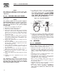
Section 1 — General Information Air-cooled 7 kW, 12 kW and 15 kW Generators 1.4 THE GENERATOR Figure 1.1 – 7 kW, Single Cylinder GH-410 Engine Oil Dipstick Control Panel Data Decal GFCI Outlet Exhaust Enclosure Fuel Regulator Fuel Inlet Oil Filter Battery Compartment Figure 1.
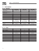
Section 1 — General Information Air-cooled 7 kW, 12 kW and 15 kW Generators 1.5 SPECIFICATIONS 1.5.1 GENERATOR Rated Max. Continuous Power Capacity (Watts*) Rated Voltage Rated Max.
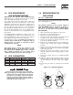
Section 1 — General Information Air-cooled 7 kW, 12 kW and 15 kW Generators 1.6 FUEL REQUIREMENTS AND RECOMMENDATIONS 1.8 With LP gas, use only the vapor withdrawal system. This type of system uses the vapors formed above the liquid fuel in the storage tank. The engine has been fitted with a fuel carburetion system that meets the specifications of the 1997 California Air Resources Board for tamper-proof dual fuel systems.
Section 1 — General Information Air-cooled 7 kW, 12 kW and 15 kW Generators NOTE: The natural gas adjustment screw is preset during installation and should not need any further adjustment. 1.8.2 12KW AND 15KW, 990CC ENGINES 13. To adjust the system to run on LP fuel, turn BOTH adjuster screws 1/2 TURN CLOCKWISE. The system should now be set for maximum power and best perfomance. DO NOT, UNDER ANY CIRCUMSTANCES, REMOVE THE SET PINS FROM THE REGULATOR HOUSING. THIS WILL VOID THE WARRANTY.
Section 1 — General Information Air-cooled 7 kW, 12 kW and 15 kW Generators 1.9.2 TRANSFER SWITCH Figure 1.5 – Battery Cable Connections 1.9.2.1 7 kW, 12 kW and 15 kW Units Transfer switches for use with these generators are sold separately and can be purchased from Authorized Dealers. • Install the transfer switch on a firm, sturdy supporting structure. • To prevent switch distortion, level the switch if necessary. This can be done by placing washers between the switch enclosure and mounting surface.
Section 2 — Post Installation Start-up and Adjustments Air-cooled 7 kW, 12 kW and 15 kW Generators • • • • Remove watches, rings or other metal objects; Use tools with insulated handles; Wear rubber gloves and boots; Do not lay tools or metal parts on top of the battery; and • Disconnect charging source prior to connecting or disconnecting battery terminals. not open or mutilate the battery. Released Do electrolyte has been known to be harmful to the skin and eyes, and to be toxic.
Section 2 — Post Installation Start-up and Adjustments Air-cooled 7 kW, 12 kW and 15 kW Generators 3. Check utility power source voltage across terminals N1 and the transfer switch neutral lug; then across terminal N2 and neutral. Nominal line-toneutral voltage should be 120 volts AC. 4. When certain that utility supply voltage is compatible with transfer switch and load circuit ratings, turn OFF the utility power supply to the transfer switch. 5.
Section 2 — Post Installation Start-up and Adjustments Air-cooled 7 kW, 12 kW and 15 kW Generators 4. Manually set the transfer switch to the UTILITY position, i.e., load terminals connected to the utility power source side. 5. Turn ON the utility power supply to the transfer switch, using the means provided (such as a utility main line circuit breaker). 6. Set the AUTO/OFF/MANUAL switch to AUTO. Then set the generator’s main circuit breaker to its ON (or closed) position.
Section 2 — Post Installation Start-up and Adjustments Air-cooled 7 kW, 12 kW and 15 kW Generators not make any unnecessary adjustments. Do Factory settings are correct for most applications. However, when making adjustments, be careful to avoid overspeeding the engine. If this procedure or equipment are not available, locate the nearest Authorized Dealer and they can perform the adjustments. NOTE: A service fee may be charged for this adjustment. 2.7 5.
Section 3 — Operation Air-cooled 7 kW, 12 kW and 15 kW Generators 5. Remove load, stop engine, loosen the idle adjust screw and reconnect the idle spring. 6. Using a hand, push the governor arm to the closed throttle position. Make sure the idle spring does not stretch at all. 7. Restart the unit. 8. Slowly turn the idle adjust screw to adjust the noload idle frequency to 63-63.5 Hz. 9. The governor is now set. 2.7.
Section 3 — Operation Air-cooled 7 kW, 12 kW and 15 kW Generators the switch set to AUTO, the engine may With crank and start at any time without warning. Such automatic starting normally occurs when utility power source voltage drops below a preset level or during the normal exercise cycle. To prevent possible injury that might be caused by such sudden starts, always set the switch to OFF and remove both fuses before working on or around the generator or transfer switch.
Section 3 — Operation Air-cooled 7 kW, 12 kW and 15 kW Generators 4. Use the manual transfer handle inside the transfer switch to move the main contacts to their “Standby” position, i.e., loads connected to the standby power source (Figure 3.2). 5. To crank and start the engine, set the AUTO/OFF/ MANUAL switch to MANUAL. 6. Let the engine stabilize and warm up for a few minutes. 7. Set the generator’s main circuit breaker to its ON (or closed) position. The standby power source now powers the loads.
Section 4 — Maintenance Air-cooled 7 kW, 12 kW and 15 kW Generators 3.7.2 HIGH TEMPERATURE SWITCH 4.1 FUSE This switch’s contacts (Figure 3.3) close if the temperature should exceed approximately 140º C (284º F), initiating an engine shutdown. The generator will automatically restart and the LED will reset once the temperature has returned to a safe operating level. The generator panel’s 15 amp fuse (Figure 4.1) protects the DC control circuit against overload.
Section 4 — Maintenance Air-cooled 7 kW, 12 kW and 15 kW Generators 3. Install the dipstick; then, remove it again. The oil level should be at the dipstick “Full” mark. If necessary, add oil to the “Full” mark only. DO NOT FILL ABOVE THE “FULL” MARK. operate the engine with the oil level Never below the “Add” mark on the dipstick. Doing this could damage the engine. 4. Install the dipstick. 5. Reset the AUTO/OFF/MANUAL switch to its original position. 2.
Section 4 — Maintenance Air-cooled 7 kW, 12 kW and 15 kW Generators 3. Wipe away dust or debris from inside of the air box and around edges. 4. Install the new air cleaner into the air box. 5. Install the cover. Turn the two cover screws clockwise to tighten. See the “Service Schedule,” Section 4.13 for air cleaner maintenance. See Section 1.5.1 for air filter replacement part number. 2. Remove the spark plug(s) and check the condition. Replace the spark plug(s) if worn or if reuse is questionable.
Section 4 — Maintenance Air-cooled 7 kW, 12 kW and 15 kW Generators not open or mutilate the battery. Released elec Do trolyte has been known to be harmful to the skin and eyes, and to be toxic. electrolyte is a dilute sulfuric acid that is harm The ful to the skin and eyes. It is electrically conductive • • • • and corrosive.
Section 4 — Maintenance Air-cooled 7 kW, 12 kW and 15 kW Generators Without sufficient cooling and ventilating air flow, the engine/generator quickly overheats, which causes it to quickly shut down. (See Figure 4.9 for vent locations.) exhaust from this product gets extremely The hot and remains hot after shutdown. High grass, weeds, brush, leaves, etc. must remain clear of the exhaust. Such materials may ignite and burn from the heat of the exhaust system. Figure 4.9 – Cooling Vent Locations 3.
Section 4 — Maintenance Air-cooled 7 kW, 12 kW and 15 kW Generators 4.13 SERVICE SCHEDULE ATTENTION: It is recommended that all service work be performed by the nearest Authorized Dealer. SYSTEM/COMPONENT X = Action R = Replace as Necessary * = Notify Dealer if Repair is Needed.
Section 5 — Troubleshooting Air-cooled 7 kW, 12 kW and 15 kW Generators 5.1 TROUBLESHOOTING GUIDE Problem Cause Correction The engine will not crank. 1. Fuse blown 1. Replace 15A fuse on generator control panel. 2. Tighten, clean or replace as necessary. 3. * 4. * 5. Charge or replace battery. 2. Loose, corroded or defective battery cables 3. Defective starter contactor (7 kW) 4. Defective starter motor 5. Dead Battery The engine cranks but will not start. 1. Out of fuel 2.
Section 6 — Electrical Data Air-cooled 7 kW, 12 kW and 15 kW Generators Wiring Diagram – 12 & 15 kW – Drawing No.
Section 6 — Electrical Data Air-cooled 7 kW, 12 kW and 15 kW Generators Wiring Diagram – 12 & 15 kW – Drawing No.
Section 6 — Electrical Data Air-cooled 7 kW, 12 kW and 15 kW Generators Electrical Schematic – 12 & 15 kW – Drawing No.
Section 6 — Electrical Data Air-cooled 7 kW, 12 kW and 15 kW Generators Electrical Schematic – 12 & 15 kW – Drawing No.
Section 6 — Electrical Data Air-cooled 7 kW, 12 kW and 15 kW Generators Wiring Diagram – 7 kW – Drawing No.
Section 6 — Electrical Data Air-cooled 7 kW, 12 kW and 15 kW Generators Wiring Diagram – 7 kW – Drawing No.
Section 6 — Electrical Data Air-cooled 7 kW, 12 kW and 15 kW Generators Electrical Schematic – 7 kW – Drawing No.
Section 6 — Electrical Data Air-cooled 7 kW, 12 kW and 15 kW Generators Electrical Schematic – 7 kW – Drawing No.
Section 7 — Exploded Views and Parts Lists Air-cooled 7 kW, 12 kW and 15 kW Generators Enclosure – Drawing No.
Section 7 — Exploded Views and Parts Lists Air-cooled 7 kW, 12 kW and 15 kW Generators Enclosure – Drawing No. 0F0080-C ITEM PART NO. QTY.
Section 7 — Exploded Views and Parts Lists 5 44 17 51 29 22 37 8,9 38 27 34 19 46 10 47 45 44 48 49 6 38 7 21 2 4 17 49 23 27 13 2 33 40 15 20 49 43 45 39 21 1 41 15 35 3 11 30 47 45 24 45 31 47 Air-cooled 7 kW, 12 kW and 15 kW Generators Control Panel – Drawing No.
Section 7 — Exploded Views and Parts Lists Air-cooled 7 kW, 12 kW and 15 kW Generators Control Panel – Drawing No. 0E7974-G ITEM PART NO. QTY.
36 42 41 40 38 45 44 39 143 37 46 43 29 28 50 52 55 51 26 31 32 3 47 48 49 27 3 140 34 53 30 25 54 56 144 24 23 33 35 36 34 58 57 59 16A 16A 60 18 17 16B 21 22 61 63 64 20 14 13 65 8 12 11 1 10 2, 5, 19, 20, 39, 40, 47, 64, 93, 140 8, 11, 12, 13 4, 5, 6 16A, 16B, 17, 18 7, 47, 48, 49, 50, 51, 52, 53, 54, 56, 57, 58, 59, 60, 63, 64 47, 48, 49, 50, 51, 52, 53, 54, 56, 57, 58, 59, 60, 62, 63, 64 27, 28, 29 3, 32, 33, 34, 35, 36, 40, 72 19 62 15 66 67 68
Section 7 — Exploded Views and Parts Lists Air-cooled 7 kW, 12 kW and 15 kW Generators GT-990 Engine – Drawing No. 0E8774-M Part 1 ITEM PART NO. QTY.
Section 7 — Exploded Views and Parts Lists Air-cooled 7 kW, 12 kW and 15 kW Generators GT-990/760 Engine – Drawing No.
Section 7 — Exploded Views and Parts Lists Air-cooled 7 kW, 12 kW and 15 kW Generators GT-990/760 Engine – Drawing No. 0E8774-M Part 2 ITEM PART NO. QTY.
Section 7 — Exploded Views and Parts Lists Air-cooled 7 kW, 12 kW and 15 kW Generators 7 kW Generator – Drawing No.
Section 7 — Exploded Views and Parts Lists Air-cooled 7 kW, 12 kW and 15 kW Generators 7 kW Generator – Drawing No. 0D3504-E ITEM PART NO. QTY.
Section 7 — Exploded Views and Parts Lists 28 29 27 28 17 13 11 23 5 24 43 7 21 34 12 33 39 6 8 4 9 31 37 32 31 28 40 38 3 20 14 2 22 15 1 19 10 17 32 10 19 32 30 25 24 16 26 29 36 35 28 18 36 41 42 10 41 31 36 32 35 36 Air-cooled 7 kW, 12 kW and 15 kW Generators 12 kW and 15 kW Generator – Drawing No.
Section 7 — Exploded Views and Parts Lists Air-cooled 7 kW, 12 kW and 15 kW Generators 12 kW and 15 kW Generator – Drawing No. 0D3417-L ITEM 1 2 3 4 5 6 7 8 9 10 11 12 13 14 15 16 17 18 19 20 21 22 23 24 25 26 27 28 29 30 31 32 33 34 35 36 37 38 39 40 41 42 43 PART NO. QTY.
Section 7 — Exploded Views and Parts Lists 42 17 31 25 30 29 28 27 37 24 35 36 23 33 45 43 39 19 18 20 34 46 44 11 32 22 48 47 26 41 38 40 51 25 12 13 14 50 49 1 6 54 16 52 1 2 5 10 4 3 7 11 8 9 Air-cooled 7 kW, 12 kW and 15 kW Generators GN410 Engine – Drawing No.
Section 7 — Exploded Views and Parts Lists Air-cooled 7 kW, 12 kW and 15 kW Generators GN410 Engine – Drawing No. 0F3981-A Part 1 ITEM 1 2 3 4 5 6 7 8 9 10 11 12 13 14 15 16 17 18 19 20 21 22 23 24 25 26 27 28 29 30 31 32 33 34 35 36 37 38 39 40 41 42 43 44 45 46 47 48 49 50 51 52 53 54 PART NO.
Section 7 — Exploded Views and Parts Lists 26 34 27 46 6 12 7 19 6 20 41 43 45 21 40 3 39 5 6 28 14 1 17 18 13 8 4 31 24 30 6 9 11 52 42 48 10 32 25 18 18 34 33 2 6 37 6 Air-cooled 7 kW, 12 kW and 15 kW Generators GN410 Engine – Drawing No.
Section 7 — Exploded Views and Parts Lists Air-cooled 7 kW, 12 kW and 15 kW Generators GN410 Engine – Drawing No. 0F3981-A Part 2 ITEM 1 2 3 4 5 6 7 8 9 10 11 12 13 14 15 16 17 18 19 20 21 22 23 24 25 26 27 28 29 30 31 32 33 34 35 36 37 38 39 40 41 42 43 44 45 46 47 48 49 50 51 52 PART NO.
Section 7 — Exploded Views and Parts Lists 21 13 13 26 48 11 10 32 28 12 20 21 25 24 23 22 19 17 12 28 10 15 14 11 3 27 31 4 2 5 16 29 18 8 17 1 26 15 14 37 16 9 30 19 22 10 23 29 18 24 11 25 12 20 28 Air-cooled 7 kW, 12 kW and 15 kW Generators Gas Regulator – Drawing No.
Section 7 — Exploded Views and Parts Lists Air-cooled 7 kW, 12 kW and 15 kW Generators Gas Regulator – Drawing No. 0D8720-G ITEM 1 2 3 4 5 8 9 10 11 12 13 14 15 16 17 18 19 20 21 22 23 24 25 26 27 28 29 30 31 32 37 PART NO. 0D5694 0F5022 0C4647 0D4166 0C6070 0F4795 0C5760J 0C6606 097934 0C4645 0C5761 0C5968 0C6066 0C5759 0C5764 0C5764A 070728 0C6069 0C5762 045764 0C6731 0C6067 0C4706 0C6068 0C4643A 026073 026073 0A4032 0D3308 024310 028414A 0D5698A 0D3973 QTY.
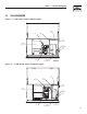
50 716 [28 743 [29 M6PEM M6P M6PEM-T PE T LEFT SIDE VIEW 622 [24.5"] 604 [23.5"] 76.2mm [3.00"] PEA GRAVEL MINUMUM 704 [27.7"] 207 [8.14"] TRANSFER SWITCH (IF SUPPLIED) 308 [12"] FRONT VIEW 1232 [48.5"] 1193 [47"] "DO NOT LIFT BY THE ROOF" LIFTING HOLES 4-CORNERS Ø30.2mm [Ø1.19"] 149 [5.9"] RIGHT SIDE VIEW 490.7 [ AIR 260 [10.2"] **ALL DIMENSIONS IN: MILLIMETERS [INCHES] REAR VIEW ROUNDING LUG CABLE ACCESS HOLES.
Section 9 — Notes Air-cooled 7 kW, 12 kW and 15 kW Generators 51
Section 10 – Warranty Air-cooled 7 kW, 12 kW and 15 kW Generators NOTE: This Emission Control Warranty Statement pertains to this product only IF the generator size is 15 kW or below. CALIFORNIA AND FEDERAL EMISSION CONTROL WARRANTY STATEMENT YOUR WARRANTY RIGHTS AND OBLIGATIONS The California Air Resources Board (CARB) and the United States Environmental Protection Agency (EPA), together with Generac Power Systems, Inc.
Section 10 – Warranty Air-cooled 7 kW, 12 kW and 15 kW Generators EMISSION CONTROL SYSTEM WARRANTY Emission Control System Warranty (ECS Warranty) for 1997 and later model year engines: (a) Applicability: This warranty shall apply to 1997 and later model year engines. The ECS Warranty Period shall begin on the date the new engine or equipment is purchased by/delivered to its original, end-use purchaser/owner and shall continue for 24 consecutive months thereafter.
Section 10 – Warranty Air-cooled 7 kW, 12 kW and 15 kW Generators GENERAC POWER SYSTEMS "TWO YEAR" LIMITED WARRANTY FOR GUARDIAN® "PREPACKAGED EMERGENCY AUTOMATIC STANDBY GENERATORS" For a period of two years from the date of original sale, Generac Power Systems, Inc. (Generac) warrants that its Guardian generator will be free from defects in material and workmanship for the items and period set forth below.