QUIETPACT® 75D DIAGNOSTIC REPAIR MANUAL RECREATIONAL VEHICLE GENERATOR MODEL 4270
SAFETY Throughout this publication, "DANGER!" and "CAUTION!" blocks are used to alert the mechanic for special instructions concerning a particular service or operation that might be hazardous if performed incorrectly or carelessly. PAY CLOSE ATTENTION TO THEM. DANGER! UNDER THIS HEADING WILL BE FOUND SPECIAL INSTRUCTIONS WHICH, IF NOT COMPLIED WITH, COULD RESULT IN PERSONAL INJURY OR DEATH.
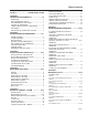
Table of Contents SAFETY ............................ INSIDE FRONT COVER SECTION 1: GENERATOR FUNDAMENTALS ...................... 3-7 MAGNETISM ................................................................ ELECTROMAGNETIC FIELDS .................................... ELECTROMAGNETIC INDUCTION .............................. A SIMPLE AC GENERATOR ........................................ A MORE SOPHISTICATED AC GENERATOR ............ FIELD BOOST ..............................................................
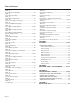
Table of Contents TEST 10 Check Brushes & Slip Rings ........................................ 42 TEST 11 Check Rotor Assembly ............................................ 42-43 TEST 12 Check Main Circuit Breaker .......................................... 43 TEST 13 Check Load Voltage & Frequency ................................ 43 TEST 14 Check Load Watts & Amperage .................................. 43 TEST 15 Check Battery Charge Output ................................
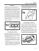
Section 1 GENERATOR FUNDAMENTALS MAGNETISM Magnetism can be used to produce electricity and electricity can be used to produce magnetism. Much about magnetism cannot be explained by our present knowledge. However, there are certain patterns of behavior that are known. Application of these behavior patterns has led to the development of generators, motors and numerous other devices that utilize magnetism to produce and use electrical energy. See Figure 1-1.
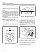
Section 1 GENERATOR FUNDAMENTALS A SIMPLE AC GENERATOR Figure 1-4 shows a very simple AC Generator. The generator consists of a rotating magnetic field called a ROTOR and a stationary coil of wire called a STATOR. The ROTOR is a permanent magnet which consists of a SOUTH magnetic pole and a NORTH magnetic pole. As the MOTOR turns, its magnetic field cuts across the stationary STATOR. A voltage is induced into the STATOR windings.
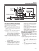
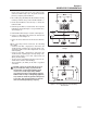
Section 1 GENERATOR FUNDAMENTALS Figure 1-7. – Generator Operating Diagram NOTE: AC output frequency at 3720 rpm will be about 62-Hertz. The “No-Load” is set slightly high to prevent excessive rpm, frequency and voltage droop under heavy electrical loading. Generator operation may be described briefly as follows: 1. Some “residual” magnetism is normally present in the rotor and is sufficient to induce approximately 7 to 12 VAC Into the stator's AC power windings. 2.
Section 1 GENERATOR FUNDAMENTALS FIELD BOOST When the engine is cranked during startup, the engine control circuit board Terminals 9, 10, and 11 (Wire 14) are energized with 12 VDC. Connected to a Wire 14 is a resistor (R2) and a diode (D2). Battery current flows through the 20 ohm 12-watt resistor and the field boost diode D2, the voltage is reduced to 3-5 VDC. After passing through R2 and D2 it becomes Wire 4 and current travels to the Rotor via brushes and slip rings.
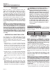
Section 1 GENERATOR FUNDAMENTALS Reroute stator lead 44 from the line side terminal of CB1 (renamed as CB1A in Figure 1-9) to the ground stud location previously occupied by stator lead Wire 33. 2. Move smaller gauge (#18 AWG) Wire labeled #44 (not shown), from the top of CB1A to the top of CB1. Renumber this Wire 11. 3. Reroute stator lead Wire 33, removed in step 1, to the line side terminal on CB1A. 4.
Section 2 MAJOR GENERATOR COMPONENTS ENGINE BRUSH HOLDER FLYWHEEL/PULLEY STATOR BEARING ROTOR BEARING BEARING CARRIER TENSIONER BEARING CARRIER PULLEY BELT Figure 2-1. Exploded View of Generator ROTOR ASSEMBLY STATOR ASSEMBLY The Rotor is sometimes called the “revolving field”, since it provides the magnetic field that induces a voltage into the stationary Stator windings. Slip rings on the Rotor shaft allow excitation current from the voltage regulator to be delivered to the Rotor windings.
Section 2 MAJOR GENERATOR COMPONENTS 3. Two excitation winding output leads (No. 2 and 6). These leads deliver unregulated excitation current to the voltage regulator. TO ENGINE CONTROLLER CIRCUIT BOARD 4. Three (3) battery charge output leads (No. 55, 66 and 77).
Section 2 MAJOR GENERATOR COMPONENTS 11 2 22 4 1 6 162 VOLTAGE ADJUST POT 162 LED Figure 2-7. – Voltage Regulator Figure 2-6. – Excitation Circuit Breaker VOLTAGE REGULATOR: Six (6) leads are connected to the voltage regulator as follows: • Two (2) SENSING leads deliver ACTUAL AC output voltage signals to the regulator. These are Wires No. 11 and 22. • Two (2) leads (4 and 1) deliver the regulated direct current to the Rotor, via brushes and slip rings. • Two (2) leads (No.
Section 2 MAJOR GENERATOR COMPONENTS CONTROL PANEL COMPONENT IDENTIFICATION Figure 2-9.
Section 3 INSULATION RESISTANCE TESTS EFFECTS OF DIRT AND MOISTURE Moisture and dirt are harmful to the continued good operation of any generator set. If moisture is allowed to remain in contact with the Stator and Rotor windings, some of the moisture will be retained in voids and cracks of the winding insulation. This will result in a reduced insulation resistance and, eventually, the unit's AC output will be affected. Insulation used in the generator is moisture resistant.
Section 3 INSULATION RESISTANCE TESTS DANGER!: DO NOT ATTEMPT TO WORK WITH SOLVENTS IN ANY ENCLOSED AREA. PROVIDE ADEQUATE VENTILATION WHEN WORKING WITH SOLVENTS. WITHOUT ADEQUATE VENTILATION, FIRE, EXPLOSION OR HEALTH HAZARDS MAY EXIST . WEAR EYE PROTECTION. WEAR RUBBER GLOVES TO PROTECT THE HANDS. CLOTH OR COMPRESSED AIR: For small parts or when dry dirt is to be removed, a dry cloth may be satisfactory. Wipe the parts clean, then use low pressure air at 30 psi (206 Kpa) to blow dust away.
Section 3 INSULATION RESISTANCE TESTS a. b. c. d. Across Wires No. 33 and 2. Across Wires No. 11 (POWER) and 66. Across Wires No. 33 and 66. Across Wires No. 2 and 66. If a breakdown in the insulation between isolated windings is indicated, clean and dry the Stator. Then, repeat the test. If the Stator fails the second test, replace the Stator assembly. TEST BETWEEN PARALLEL WINDINGS: Connect the tester leads across Stator leads No. 11 (POWER) and 33. Apply a voltage of 1500 volts.
Section 4 MEASURING ELECTRICITY METERS MEASURING AC VOLTAGE Devices used to measure electrical properties are called meters. Meters are available that allow one to measure (a) AC voltage, (b) DC voltage, (c) AC frequency, and (d) resistance in ohms. The following apply: • To measure AC voltage, use an AC voltmeter. • To measure DC voltage, use a DC voltmeter. • Use a frequency meter to measure AC frequency in “Hertz” or “cycles per second”.. • Use an ohmmeter to read circuit resistance, in “ohms”.
Section 4 MEASURING ELECTRICITY MEASURING AC FREQUENCY The generator's AC output frequency is proportional to Rotor speed. Generators equipped with a 2-pole Rotor must operate at 3600 rpm to supply a frequency of 60-Hertz. Correct engine and Rotor speed is maintained by an engine speed governor. For models rated 60-Hertz, the governor is generally set to maintain a no-load frequency of about 62-Hertz with a corresponding output voltage of about 125 VAC line-to-neutral.
Section 4 MEASURING ELECTRICITY ELECTRICAL UNITS AMPERE: The rate of electron flow in a circuit is represented by the AMPERE. The ampere is the number of electrons flowing past a given point at a given time. One AMPERE is equal to just slightly more than six thousand million billion electrons per second. With alternating current (AC), the electrons flow first in one direction, then reverse and move in the opposite direction. They will repeat this cycle at regular intervals.
Section 5 ENGINE DC CONTROL SYSTEM INTRODUCTION The engine DC control system includes all components necessary for the operation of the engine. Operation includes off, preheat, cranking/starting, running, shutdown, and fault shutdown. The system is shown schematically. OPERATIONAL ANALYSIS CIRCUIT CONDITION- OFF: Battery voltage is available to the engine controller circuit board from the unit BATTERY and via (a) the RED battery cable, Wire 13, a 14 amp FUSE (F1), Wire 15 and engine controller Terminal 1.
Section 5 ENGINE DC CONTROL SYSTEM CIRCUIT CONDITION- PRE-HEAT: When the PRE-HEAT SWITCH (SW) or the REMOTE PANEL PRE-HEAT SWITCH is closed by the operator, battery voltage is delivered across the closed switch contacts to the PRE-HEAT CONTACTOR (PHC) via Wire 150. The PRE-HEAT CONTACTOR (PHC) is now energized. The normally open (PHC) contacts close, battery voltage is now available to Wire 157. The GLOW PLUGS (GP) are energized via Wire 157.
Section 5 ENGINE DC CONTROL SYSTEM CIRCUIT CONDITION- CRANKING: When the START-STOP-SWITCH (SW1) or REMOTE PANEL START-STOP-SWITCH is held at "START" position, Wire 17 from the Engine Control circuit board is connected to Ground. Engine control circuit board action will then deliver battery voltage to a STARTER CONTACTOR (SC) via Terminal 7 Wire 56. The STARTER CONTACTOR (SC) energizes and its contacts close, battery output is delivered to the STARTER MOTOR (SM) via Wire 16.
Section 5 ENGINE DC CONTROL SYSTEM CIRCUIT CONDITION-RUNNING: With the FUEL PUMP (FP) and FUEL SOLENOID (FS) operating the engine should start. The STARTSTOP SWITCH (SW1) is then released. Engine control circuit board action terminates DC output to the STARTER CONTACTOR (SC), which then de-energizes the (SC) to end cranking. While running, engine control circuit board action keeps Terminals 9, 10, and 11 energized which delivers battery voltage to the Wire 14 circuit.
Section 5 ENGINE DC CONTROL SYSTEM CIRCUIT CONDITION- SHUTDOWN: Setting the START-STOP SWITCH (SW1) or the REMOTE PANEL START-STOP SWITCH to its "STOP" position, connects the Wire 18 circuit to ground. ENGINE CONTROL circuit board action deenergizes DC output to Terminal 9,10, & 11 (Wire 14). The FUEL PUMP (FP), FUEL SOLENOID (FS) and HOURMETER (HM) are de-energized by the loss of DC to Wire 14. Fuel flow terminates and the engine shuts down.
Section 5 ENGINE DC CONTROL SYSTEM CIRCUIT CONDITION- FAULT SHUTDOWNS: The engine has mounted to it a HIGH WATER TEMPERATURE SWITCH (HWT) and a LOW OIL PRESSURE SWITCH (LOS). While running, ENGINE CONTROL circuit board action keeps Terminal 12 Wire 85 energized with battery voltage. Connected in parallel to (Wire 85) are the LOW OIL PRESSURE SWITCH (LOS) and HIGH WATER TEMP SWITCH (HWT). The (LOS) has normally closed contacts. After start-up, engine oil pressure will open the contacts.
Section 5 ENGINE DC CONTROL SYSTEM ENGINE CONTROL CIRCUIT BOARD GENERAL: The ENGINE CONTROL circuit board is responsible for cranking, startup, running, and shutdown operations. The board interconnects with other components of the DC control system to turn them on and off at the proper times. It is powered by fused 12 VDC power from the unit battery. CIRCUIT BOARD CONNECTIONS: The circuit board mounts two, six-wire terminal strips. They are labeled 1-6 and 7-12.
Section 5 ENGINE DC CONTROL SYSTEM TERMINALS: 7 8 9 10 11 12 1 2 3 4 5 6 OVERSPEED SHUTDOWN POTENTIOMETER GREEN LED RED LED TERMINALS: Figure 5-4 – Engine Control Circuit Board battery and starter should not exceed 0.12 VDC per 100 amperes of cranking current. Select the battery cables based on total cable length and prevailing ambient temperature. Generally, the longer the cable and the colder the weather, the larger the required cable diameter.
Section 5 ENGINE DC CONTROL SYSTEM 14 AMP FUSE This panel-mounted Fuse protects the DC control circuit against overload and possible damage. If the Fuse has melted open due to an overload, neither the priming function nor the cranking function will be available. WIRE 17 (FROM THE ENGINE CONTROL BOARD): This is the crank and start circuit. When the switch is set to start, Wire 17 is connected to ground via Wire 0.
Section 5 ENGINE DC CONTROL SYSTEM The positive (+) battery cable (13) attaches to one of the outer posts of the contactor along with Wire 13 for the DC supply to the fuse (F1). The starter cable (16) attaches to the remaining outer post. Attached to the small 2 lugs are Wires 56 and 0. When the start/stop switch is set to start, the circuit board delivers battery voltage to the contactor coil via Wire 56. The contactor energizes and its contacts close.
Section 5 ENGINE DC CONTROL SYSTEM HIGH COOLANT TEMPERATURE SWITCH SHEATH ASBESTOS BODY NUT HEAT-WIRE MAGNESIUM OXIDE POWDER The high coolant temperature switch has normally open contacts. This switch is immersed in engine coolant. If the coolant temperature should exceed 245-266 degrees F, the switches contacts will close to ground, sending a signal to the printed circuit board to shut down the unit via wire 85. INSULATING BUSHING CENTER ELECTRODE Figure 5-11.
Section 6 TROUBLESHOOTING FLOWCHARTS INTRODUCTION The “Flow Charts” in this section can be used in conjunction with the “Diagnostic Tests” of Section 7. Numbered tests in the Flow Charts correspond to identically numbered tests of Section 7. Problems 1 through 4 apply to the AC generator only. Beginning with Problem 5, the engine DC control system is dealt with.
Section 6 TROUBLESHOOTING FLOWCHARTS Page 30
Section 6 TROUBLESHOOTING FLOWCHARTS Problem 2 - Generator Produces Zero Voltage or Residual Voltage (5-12 VAC) (continued) E TEST 11 CHECK ROTOR ASSEMBLY TEST 4 PERFORM FIXED EXCITATION / ROTOR AMP DRAW CHECK VOM FUSES VERIFY AMP METER FUNCTIONS REPLACE FUSES - THEN RETEST F BAD (PERFORM BOTH TEST 7 & 8) TEST 7 - TEST STATOR DPE WINDING REPAIR OR REPLACE INSULATION RESISTANCE TEST PAGE 14 G GOOD TEST 8 - CHECK SENSING LEADS / POWER WINDINGS GOOD BAD EITHER OR BOTH BAD INSULATION RESISTANCE TE
Section 6 TROUBLESHOOTING FLOWCHARTS Page 32
Section 6 TROUBLESHOOTING FLOWCHARTS Page 33
Section 6 TROUBLESHOOTING FLOWCHARTS Page 34
Section 6 TROUBLESHOOTING FLOWCHARTS Page 35
Section 6 TROUBLESHOOTING FLOWCHARTS Page 36
Section 7 DIAGNOSTIC TESTS INTRODUCTION 3. If AC output voltage and frequency are both “zero”, go to Test 12. The “Diagnostic Tests” in this chapter may be performed in conjunction with the “Flow Charts” of Section 6. Test numbers in this chapter correspond to the numbered tests in the “Flow Charts”. Tests 1 through 17 are procedures involving problems with the generator's AC output voltage and frequency (Problems 1 through 4 in the “Flow Charts”).
Section 7 DIAGNOSTIC TESTS line voltage should read between 242-252 VAC. If voltage and frequency are good, no adjustment is needed. If voltage and frequency are low or high, proceed to next step. 4. Turn the governor adjusting screws to obtain a no-load frequency as close as possible to 62-63 HERTZ. With no-load frequency set, apply an electrical load as close as possible to the unit's rated load. Frequency with load applied should not fall below 58 HERTZ.
Section 7 DIAGNOSTIC TESTS TEST 4 RESULTS C D A B E F G VOLTAGE RESULTS WIRE 2 & 6 EXCITATION WINDING ABOVE 60 VAC ABOVE 60 VAC BELOW 60 VAC ZERO OR RESIDUAL VOLTAGE (5-12 VAC) BELOW 60 VAC BELOW 60 VAC ABOVE 60 VAC VOLTAGE RESULTS WIRE 11 & 22 POWER WINDING SENSE LEADS ABOVE 60 VAC BELOW 60 VAC ABOVE 60 VAC ZERO OR RESIDUAL VOLTAGE (5-12 VAC) BELOW 60 VAC BELOW 60 VAC ABOVE 60 VAC ROTOR AMP DRAW QP75D (MODEL 4270) .87-.79 A ± 20% .87-.79 A ± 20% .87-.
Section 7 DIAGNOSTIC TESTS 3. Set the Start-Stop Switch to “START.” During cranking only, measure DC voltage. It should read 3-5 VDC. Reconnect Wire 4 to the Voltage Regulator. If voltage is measured, it can be assumed that the Field Boost is working. Stop testing. If voltage is not measured, proceed to Step 4. 4. Test D2 diode: Place a VOM to measure continuity. Place one test lead on one end of the diode and the other test lead on the other end. Check for continuity, then reverse the leads and retest.
Section 7 DIAGNOSTIC TESTS TEST 8- CHECK SENSING LEADS / POWER WINDINGS DISCUSSION: The Voltage Regulator “regulates” excitation current flow to the Rotor by electronically comparing sensing voltage to a pre-set reference voltage. The sensing voltage is delivered to the Voltage Regulator via Wires 11 and 22.
Section 7 DIAGNOSTIC TESTS one meter test lead to Wire 1. Connect the other test lead to a clean ground. The meter should read “Continuity”. RESULTS: 1. Repair, reconnect or replace any defective wire(s). 2. If wires check good, go to Test 10. 4 1 Figure 7-6. – Brush Leads TEST 10 - CHECK BRUSHES & SLIP RINGS DISCUSSION: Brushes and slip rings are made of special materials that will provide hundreds of hours of service with little wear.
Section 7 DIAGNOSTIC TESTS RESULTS: 1. Replace the Rotor if it fails the test. 2. If Rotor checks good, perform “Insulation Resistance Test,” on Page 14. TEST 12 - CHECK MAIN CIRCUIT BREAKER DISCUSSION: The main circuit breaker on the generator panel must be closed or no output to the load will be available. A defective breaker may not be able to pass current even though it is in the “ON” position.
Section 7 DIAGNOSTIC TESTS approximately 0.8 Amps. Apply full load to the generator. The amp reading should increase to approximately 2 Amps. RESULTS: 1. If amperage was measured between 0.8 to 2 Amps in Step 2 and Step 3, the charging system is working. 2. If no amperage was measured, check the VOM fuses and verify the functioning of the Amp Meter.
Section 7 DIAGNOSTIC TESTS * Resistance values in ohms at 20° C. (68° F.). Actual readings may vary depending on ambient temperature. A tolerance of plus or minus 5% is allowed. RESULTS: 1. For Steps 2 & 3, keep in mind that the resistance values are very low. Depending upon the quality of the VOM, it may read “Continuity” across these windings. Exercise good judgement with these values. 2. If Steps 2, 3, 4, 5 & 6 fail any test, replace the Stator. 3.
Section 7 DIAGNOSTIC TESTS PROCEDURE: 1. Set a VOM to measure DC voltage. 2. Disconnect the connector from the wires of the fuel pump. 3. Place the positive (+) test lead on Wire 14 and the negative (-) test lead to clean ground. Press the pre-heat switch, battery voltage should be measured, if not, disconnect the other end of Wire 14. Place test leads on each end of Wire 14. Set a VOM to measure continuity. Continuity should be measured. 4. Disconnect Wire 0 from the black wire of the fuel pump.
Section 7 DIAGNOSTIC TESTS 3. Set the VOM to measure resistance (“Rx1” scale). Connect one meter test lead to Wire 0, Terminal 2 on the Engine Controller Circuit Board. Connect the other test lead to a clean frame ground. “Continuity” should be measured. PROCEDURE: For Problem 6 (Section 6), perform all steps. For Problem 9, perform Step 1 and Step 5 ONLY. 1. Set a VOM to its “Rx1” scale and zero the meter. RESULTS: 1. If battery voltage is NOT indicated in Step 1, check continuity of: 2.
Section 7 DIAGNOSTIC TESTS RESULTS: 1. If “Continuity” is not measured in Step 2, repair, reconnect or replace Wire 0 (between Start-Stop Switch and ground terminal) as necessary. 2. If engine cranks in Step 3 when Wire 17 is grounded, but will not crank when the Switch is set to “START”, replace the StartStop Switch. 3. If the Start-Stop Switch (SW1) failed any part of Steps 5 or 6, replace the switch. 4. If engine will not crank when Wire 17 is grounded, proceed as follows: a.
Section 7 DIAGNOSTIC TESTS b. Open armature (wire broken) will be indicated by low or no RPM and excessive current draw. c. Grounded armature (wire insulation worn and wire touching armature lamination or shaft). Will be indicated by excessive current draw or no RPM. 3. A defective Starter Motor switch. 4. Broken, damaged or weak magnets. 5. Starter drive dirty or binding. DISCUSSION: Test 25 verified that circuit board action is delivering DC voltage to the Starter Contactor Relay (SCR).
Section 7 DIAGNOSTIC TESTS TEST BRACKET: A starter motor test bracket may be made as shown in Figure 7-18. REMOVE STARTER MOTOR: It is recommended that the Starter Motor be removed from the engine when testing Starter Motor performance. Assemble starter to test bracket and clamp test bracket in vise (Figure 7-19). TESTING STARTER MOTOR: 1. A fully charged 12 VDC battery is required. 2. Connect jumper cables and clamp-on ammeter as shown in Figure 7-19. 3.
Section 7 DIAGNOSTIC TESTS TEST 28- CHECK FUEL SUPPLY DISCUSSION: If the engine cranks but won't start, don't overlook the obvious. The fuel supply may be low. Many RV generator installations "share" the fuel tank with the vehicles engine. When such is the case, the installer may have used a generator fuel pickup tube that is shorter than the vehicle engines pickup tube. Therefore, the generator will run out of fuel before the vehicle engine does. PROCEDURE: 1. Check the fuel level in the supply tank. 2.
Section 7 DIAGNOSTIC TESTS 6. Place test leads on each end of wire, continuity should be measured. 2. If resistance is incorrect in step 6, then replace preheat contactor. 7. If continuity is measured, test battery voltage on Wire 14 going to circuit board on Pin 10, with prime switch pressed. Meter should read battery voltage. 3. If prime function did not occur in step 7, and resistance was incorrect in step 6, proceed to next test on flow chart. 8. Set a VOM to measure resistance. 9.
Section 7 DIAGNOSTIC TESTS TEST 35- CHECK VALVE ADJUSTMENT DISCUSSION: If the engine is having a hard start, no start, or rough running condition, then the valves will need to be checked for proper clearance. If a unit has a lot of hours on it, the valves will need to be readjusted. 6. Turn the crankshaft counterclockwise by 204° (view from front) to adjust the clearance of the intake valve of No. 2 cylinder and the intake and exhaust valves of the No. 3 cylinder. PROCEDURE: 1.
Section 7 DIAGNOSTIC TESTS 8. Crank engine again and see if fuel is coming out of the fuel lines. RESULTS: 1. If no fuel is noted in Steps 3 or 8, replace fuel injector pump. (Reinstallation of all original shims will be required.) 2. If fuel is noted, proceed to next step in flowchart. TEST 37 - CHECK ENGINE / CYLINDER LEAK DOWN TEST / COMPRESSION TEST GENERAL: Most engine problems may be classified as one or a combination of the following: • Will not start. • Starts hard. • Lack of power. • Runs rough.
Section 7 DIAGNOSTIC TESTS NOTE: For units out of warranty, refer to Quicksilver Diagnostic & Service Manual - Diesel, P/N 082034 for further engine service information. This manual can be found at www.guardiangenerators.com, under “Brochures,Manual & Specs Recreational Vehicle - Manuals”. TEST 38 - CHECK OIL PRESSURE SWITCH DISCUSSION: Also see “Operational Analysis” on Pages 18-23. The Low Oil Pressure Switch is normally-closed, but is held open by engine oil pressure during cranking and startup.
Section 7 DIAGNOSTIC TESTS RESULTS: 1. If continuity is measure, replace the switch. 2. If infinity is measured, proceed to next test on the flow chart. TEST 41- CHECK WIRE 14 AND CONNECTING COMPONENTS FOR SHORT TO GROUND DISCUSSION: Once the start/stop switch is pressed, the circuit board will take battery voltage from Wire 15 on Pin 1 and provide it to Wires 14 on Pins 9,10,11. If Wire 14 or any components attached to 14 are shorted to ground, the 14-amp fuse will blow.
Section 8 ASSEMBLY MAJOR DISASSEMBLY 11. Remove the two hold down bolts mounting the brush assembly to the rear-bearing carrier. ENCLOSURE/ PANEL REMOVAL: Using a 10-mm socket, remove all screws on all panels except the lower screws on the radiator side panel. Remove the top panel first, then the side and rear. When removing the front panel, the main control panel is mounted onto the front sheet metal. There are five nuts holding them together that will need to be removed in order to separate.
Section 8 ASSEMBLY 4. Attach a hoist hook to the top lifting bracket attached to the engine. 2. Loosen drain plug and drain coolant into appropriate container able to hold 1.4 gallons. 5. Slightly lift the engine to take pressure off of the block of wood. 3. With the coolant drained, lower the unit and remove the lower and 2 upper coolant hoses. 6. Remove the bolts holding front cross member frame to the engine.
Section 8 ASSEMBLY LINE UP ARROW WITH 15˚ MARK Figure 8-5. – Applying Tension to Drive Belt Tensioner Figure 8-7. – Position of Fan Belt Tensioner LINE CORNER UP BETWEEN 5˚ to 10˚ Figure 8-8. – Leveling Fan Belt Tensioner Figure 8-6. – Position of Drive Belt Tensioner FAN BELT: 1. Install fan belt tensioner as shown in Figure 8-7. Snug mounting bolt but do not tighten. 2. Using a small bubble level, verify that tensioner is level horizontally.
Section 9 Exploded Views / Part Numbers 9 32 24 21 1 2 6 4 3 23 5 21 25 26 41 42 45 22 Page 60 22 20 38 50 13 39 2 49 26 11 44 49 28 4 40 36 21 37 19 29 28 7 43 21 17 10 39 27 26 25 31 35 18 14 33 Engine, Alternator Drive & Starter – Drawing No.
Section 9 Exploded Views / Part Numbers ITEM 1 2 3 4 5 6 7 8 9 10 11 12 13 14 15 16 17 18 19 20 21 22 23 24 25 26 27 28 29 30 31 32 33 34 35 36 37 38 39 40 41 42 43 44 45 46 47 48 49 50 QTY. 1 1 1 1 1 1 1 2 4 6 1 1 1 1 1 1 1 1 2 2 8 8 2 1 4 6 2 2 1 1 1 11 6 2 5 1 2 1 4 1 4 3 1 2 1 2 1 1 2 2 DESCRIPTION Bearing Carrier, Front Bearing Carrier, Upper Rotor Assembly Stator Assembly Ball Bearing Ball Bearing Brush Holder Taptite M5-0.
Section 9 Exploded Views / Part Numbers Base Frame – Drawing No.
Section 9 Exploded Views / Part Numbers ITEM 1 2 3 4 5 6 7 8 9 10 11 12 13 14 15 16 17 18 19 20 21 22 23 QTY. 1 1 1 4 2 677mm 4 4 1 1 8 8 3 2 1 1 3 2 2 1 1 1 1 DESCRIPTION Base Frame Weldment Door, Service Rear Door, Service Front Slide Latch Flush Vinyl Trim -Black 180mm Rubber Tape 1/8 x ½" Grommet 1/8 x 13/32 Vibration Mount Gasket, Cleanout Plate, Cleanout HHCS M8-1.25 x 16 Washer, Split Lk- M8 Washer, Split Lk -1/4-M6 HHCS M6-1.
Section 9 Exploded Views / Part Numbers Enclosure – Drawing No.
Section 9 Exploded Views / Part Numbers ITEM 1 2 3 4 5 6 7 8 9 10 11 12 13 14 15 16 17 18 19 20 21 22 23 24 25 26 27 28 29 30 31 32 33 34 35 36 37 38 QTY.
Page 66 30 12 46 42 25 40 47 34 29 27 25 5 42 43 34 3 51 33 48 25 44 45 28 34 36 4 41 34 32 41 31 19 18 2 49 39 14 21 38 37 21 20 8 15 5 23 50 (RE 4 17 14 13 39 54 6 14 5 53 1 18 3 22 55 26 7 1 9 10 11 Section 9 Exploded Views / Part Numbers Cooling System – Drawing No.
Section 9 Exploded Views / Part Numbers ITEM 1 2 3 4 5 6 7 8 9 10 11 12 13 14 15 16 17 18 19 20 21 22 23 24 25 26 27 28 29 30 31 32 33 34 35 36 37 38 39 40 41 42 43 44 45 46 47 49 51 52 53 54 55 QTY.
Section 9 Exploded Views / Part Numbers 12 14 7 28 Page 68 17 19 16 13 5 31 25 11 26 27 29 28 8 28 27 6 4 15 11 1 25 26 27 18 32 2 20 33 Electrical Enclosure Assembly – Drawing No.
Section 9 Exploded Views / Part Numbers ITEM 1 2 3 4 5 6 7 8 9 10 11 12 13 14 15 16 17 18 19 20 21 22 23 24 25 26 27 28 29 31 32 33 QTY. 1 1 1 1 1 1 1 A/R 2 1 3 2 4 1 1 1 4 1 4 1 *1 *1 *1 *1 2 2 7 7 3 4 1 1 DESCRIPTION Weldment, Electrical Enclosure Terminal Block 4 Position Assembly, Potted Regulator Resistor 20R 5% 12W Assembly Marine Control Board Rectifier, Battery Charging Circuit Breaker 5 Amp Tape, Glass Insulated Taptite, M5-0.8 x 30 Taptite, M5-0.8 x 16 Lockwasher M5 Nut, Hex M4-0.
Section 9 Exploded Views / Part Numbers Intake and Exhaust System – Drawing No.
Section 9 Exploded Views / Part Numbers ITEM 1 2 3 4 5 6 7 8 9 10 11 12 13 14 15 16 17 18 19 20 21 22 23 24 25 26 27 28 29 QTY. 1 1 1 1 1 2 1 1 3 1 1 1 2 2 10 5 3 1 4 2 4 2 1 1 2 1 1 1 1 DESCRIPTION Exhaust Gasket Chamber Air Intake Air Filter Hose, Air Inlet Muffler Weldment U Bolt & Saddle 1.25 Rail, Engine LH, Weldment Insulation, Exhaust Hose Clamp #28 Outlet, Exhaust Flex Gasket, Exhaust Outlet Plate, Exhaust Outlet HHCS M8-1.25 x 55 Washer, Vibration Isolator Washer, Split Lk -M8 Nut, Hex M8-1.
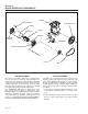
Page 72 17 17 TO GLOW PLUGS 16 26 6 TO STARTER MOTOR 29 23 16 10 TO STARTER MOTOR BOLT 20 9 25 4 8 21 16 7 18 14 17 12 27 15 4 13 4 19 2 9 26 25 22 12 10 3 24 2 5 4 11 27 7 28 1 2 12 4 TO GROUND TO STATOR Section 9 Exploded Views / Part Numbers Fuel and Electrical Systems – Drawing No.
Section 9 Exploded Views / Part Numbers ITEM 1 2 3 4 5 6 7 8 9 10 11 12 13 14 15 16 17 18 19 20 21 22 23 24 25 26 27 28 29 QTY. 1 3 2 7 1 2 5 1 5 2 1 3 1 1 1 3 3 2 1 1 1 1 1 1 1.04M 635mm 375mm 1 1 DESCRIPTION Fuel Pump Assembly 1/8 NPT x 5/16 Barbed Straight Fitting Bulkhead Adaptor Fitting Washer, Split Lk- ¼ -M6 HHCS M6-1.00 x 30 Relay Solenoid Nut, Hex M6-1 Clamp, Vinyl Coat 1-1/16" Washer, Flat -M6 Hose Clamp 1/8 NPT x 1/4 Barbed Straight Fitting Hose Clamp 7/8 / 3/8 HHCS M6-1.
Section 9 Exploded Views / Part Numbers 26 28 Page 74 25 31 22 15 22 26 21 19 13 16 24 21 23 27 12 5 11 30 17 29 7 18 32 2 33 3 9 6 34 1 10 4 8 Customer Controls Assembly – Drawing No.
Section 9 Exploded Views / Part Numbers ITEM 1 2 3 4 5 6 7 8 9 10 11 12 13 14 15 16 17 18 19 20 21 22 23 24 25 26 27 28 29 30 31 32 33 34 QTY. 1 1 1 1 1 2 2 1 1 1 4 1 1 2 1 1 1 1 1 1 2 2 4 4 1 2 1 2 4 4 2 4 1 1 DESCRIPTION Start / Stop Switch Cover, Engine Control Box Hour Meter Fuse Holder, SFE-14 Switch, Pushbutton SPST PPHMS M3-0.
Section 9 Exploded Views / Part Numbers 1.0 Liter Diesel Camshaft – Drawing No. 075677 1 3 6 5 4 10 2 13 7 12 11 8 9 ITEM 1 2 3 4 5 6 7 8 9 10 11 12 13 Page 76 5 QTY.
Section 9 Exploded Views / Part Numbers 1.0 Liter Diesel Cylinder Block – Drawing No. 075676 15 28 5 13 19 4 27 1 12 18 23 17 16 5 24 20 25 21 14 3 26 7 8 30 11 29 10 6 2 ITEM QTY. 1 2 3 4 5 6 7 8 9 10 11 1 1 1 2 2 1 4 4 1 1 1 1 1 1 1 1 1 12 13 14 15 DESCRIPTION COMPLETE CYLINDER BLOCK EXPANSION PLUG EXPANSION PLUG EXPANSION PLUG EXPANSION PLUG EXPANSION PLUG PLUG PLUG IDLE GEAR SHAFT BUSHING BUSHING-STANDARD 0.25MM U.S. BUSHING 0.50MM U.S.
Section 9 Exploded Views / Part Numbers 1.0 Liter Diesel Cylinder Head – Drawing No. 0D2794 11 10 9 8 3 13 7 14 2 20 1 4 22 2 21 18 4 23 19 6 17 16 5 12 ITEM QTY. 1 2 3 4 5 6 7 1 6 3 2 3 3 3 3 6 6 12 6 1 8 9 10 11 12 1 Page 78 DESCRIPTION CYLINDER HEAD ASSEMBLY EXPANSION PLUG EXPANSION PLUG XPANSION PLUG INTAKE VALVE EXHAUST VALVE VALVE GUIDE SEAL (EXHAUST) VALVE GUIDE SEAL (INTAKE) SPRING RETAINER KEY CAP CYLINDER HEAD GASKET, 1.2MM THICK CYLINDER HEAD GASKET, 1.3MM THICK ITEM QTY.
Section 9 Exploded Views / Part Numbers 1.0 Liter Diesel Crankshaft, Piston and Flywheel – Drawing No. 075679-B 19 17 16 18 19 22 20 21 9 9 11 11 6 12 13 7 10 15 10 14 5 1 4 2 3 28 30 ITEM QTY. 1 2 3 4 5 6 7 8 9 10 11 1 1 1 1 1 1 1 1 6 6 3 AR AR 3 AR AR 2 2 1 3 AR AR 12 13 14 15 16 DESCRIPTION CRANKSHAFT ASSEMBLY CRANKSHAFT GEAR KEY DOWEL PIN SPRING PIN BEARING HOLDER ASSEMBLY BEARING HOLDER ASSEMBLY BEARING HOLDER ASSEMBLY BOLT DOWEL PIN STANDARD BEARING 0.25MM U.S. BEARING 0.
Section 9 Exploded Views / Part Numbers 1.0 Liter Diesel Oil Pump – Drawing No. 75682 11 10 1 5 7 3 9 12 2 4 6 8 ITEM QTY. 1 2 3 4 5 6 1 1 1 1 1 AR AR AR AR 1 1 1 1 1 3 7 8 9 10 11 12 AR - AS REQUIRED Page 80 DESCRIPTION IDLER GEAR ASSEMBLY SPRING THRUST WASHER ROTOR OIL PUMP COVER 0.10MM SHIM 0.15MM SHIM 0.20MM SHIM 0.
Section 9 Exploded Views / Part Numbers 1.0 Liter Diesel Rocker Arm Assembly – Drawing No. 075683 4 5 11 6 2 3 8 12 7 9 10 ITEM QTY.
Section 9 Exploded Views / Part Numbers 1.0 Liter Diesel Injector Pump – Drawing No. 075686-C 11 9 12 10 14 8 3 13 7 19 6 (MODEL 04270 & 04614 ONLY) 5 18 3 29 28 20 19 27 17 26 4 1 16 2 ITEM QTY. 1 2 1 AR AR AR AR 3 2 3 3 3 3 1 1 1 1 3 4 5 6 7 8 9 10 11 12 DESCRIPTION INJECTOR PUMP ASSEMBLY SHIM-0.2MM SHIM-0.3MM SHIM-0.5MM SHIM-1.0MM NUT BOLT GASKET INSERT CAP INJECTOR TUBING TUBING TUBING TUBING ITEM QTY.
Section 9 Exploded Views / Part Numbers 1.0 Liter Diesel Fuel Supply – Drawing No. 075693-C 14 10 To Fuel Tank (Return) 14 14 11 19 (Model 04270 & 04614) 10 9 17 13 15 16 16 5 18 4 1 5 16 17 8 6 7 18 6 2 5 To Injection Pump 3 To Fuel Pump ITEM QTY. 1 2 3 4 5 6 7 8 9 10 1 1 AR 250MM 3 2 1 1 2 2 DESCRIPTION FUEL FILTER SUPPORT FUEL FILTER HOSE, 5/16" SAE 30R7 HOSE, 5/16" SAE 30R7 HOSE CLAMP GASKET BANJO FITTING FUEL BLEED FITTING 1/8" NPT TEE (BRASS) 1/8" NPT x 3/16" 90 DEG.
Page 84 50 49 48 44 (Model 04270 & 04614) 47 45 43 42 42 37 40 4 1 36 35 13 38 2 46 13 21 23 52 22 (Model 04270 & 04614) 51 18 8 24 27 19 39 4 1 26 28 25 13 14 5 33 31 30 20 15 34 32 29 1 16 6 3 Section 9 Exploded Views / Part Numbers 1.0 Liter Diesel Timing and Governor – Drawing No.
Section 9 Exploded Views / Part Numbers ITEM 1 2 3 4 5 6 7 8 11 12 13 14 15 16 17 18 19 20 21 22 23 24 25 26 27 28 29 30 31 32 33 34 35 36 37 38 39 40 41 42 43 44 45 46 47 48 49 50 51 52 QTY.
Section 9 Exploded Views / Part Numbers 1.0 Liter Diesel Engine Block – Drawing No. 082961-C 24 23 22 25 18 28 17 15 20 13 19 12 14 14 33 30 29 1 14 31 2 ITEM QTY. 1 2 3 1 20 1 12 1 1 13 2 14 15 5 1 Page 86 DESCRIPTION OIL PAN BOLT O-RING (MODELS 04270 & 04614 ONLY) DIPSTICK TUBE (ALL MODELS EXCEPT 04270 & 04614) DIPSTICK TUBE (MODELS 04270 & 04614 ONLY) O-RING (ALL MODELS EXCEPT 04270 & 04614) BOLT DIPSTICK (ALL MODELS EXCEPT 04270 & 04614) ITEM QTY.
Section 9 Exploded Views / Part Numbers 1.0 Liter Diesel Water Pump – Drawing No. 082962 4 3 7 5 1 2 10 6 8 15 11 9 12 ITEM 1 2 3 4 5 6 7 8 9 10 11 12 15 QTY.
Page 88 45 [1.77 "] 42 1 [16 .5 7 "] 3 7 1 [14 .6 1"] 63 [2 .4 8 "] 26 [1.02 "] 24 [.94 "] F U E L RE T U R N 67 [22 .3 2 "] ER SCREWS 53 6 .3 [2 1.12 "] 2 9.35 [1.16 "] E X HA U S T O U TL E T 5 16 .5 H O U R M E T ER COO L A N T F ILL 9 2 9 [3 6 .5 7 "] OVER SCREWS 9 17 .5 [3 6 .12 "] F RO N T SERV ICE D OOR RE A R SERV ICE P A N E L 99 [3 .90"] 289 [11.
Section 10 SPECIFICATIONS & CHARTS ENGINE SPECIFICATIONS Type of Engine Cylinder Arrangement Displacement Bore Stroke Compression Ratio Combustion Chamber Type Rated Horsepower Cylinder Block Number of Main Bearings Number of Teeth on Flywheel Type of Governor Fuel Filter Oil Filter Oil Pressure Type of Cooling System Cooling Method Type of Cooling Fan Cooling System Capacity Air Cleaner Starter Recommended Battery Maximum Cranking Current Ground Polarity ISM Diesel 3, in-line 58.2 in3. (954 cc) 2.95 in.
Section 10 SPECIFICATIONS & CHARTS ROTOR/STATOR RESISTANCE VALUES TYPE QUIETPACT 75 MODEL 4270 Rotor resistance 15.25 ohms Stator Winding 11/22 159 ohms Stator Winding 33/44 184 ohms DPE Winding 2/6 1.24 ohms Battery charge Winding 55/66 .132 ohms Battery charge Winding 55/77 .153 ohms TORQUE SPECIFICATIONS Starter Flywheel 16.2-19 ft-lbs. Rotor Pulley 34.2-41.8 ft-lbs. Stator Bolts 16.2-19.8 ft-lbs. Tension Bolt 44.1-53.9 ft-lbs. Pulley Tension 44.1-53.9 ft-lbs.
NOTES Page 91
D IOD E 600 V, 6A MP FU SE 14A MP S FE FU EL P U MP FU EL SO LEN OID E N G IN E G RO U N D FR A M E S TU D F 0 85 SM 0 16 R 1 - RESIS TOR, 1 ohm 25W R 2 - RESIS TOR 20 ohm, 12W SC - S TA R T C O N TA C TOR SM - S TA R TER M O TOR SW 1 - SWI TC H S TA R T/ STO P SW 2 - P RE H EA T SWITC H TS - TER M IN A L S TRIP CU STO M ER C O NN EC TION 14 14 0 14 FS RE D LOS 0 0 13 0 GND3 1 13 GND2 1 56 157 14 1 0 14 18 G LOW 2 85 6 150 1 44 13 18 17 P LU G S 0 SH EET GND6 B H2
12- D IODE 600 V, 6A M P FU SE 14A M P SFE FUEL PU M P FUEL SOLENO ID ENG INE GROUND FR A M E STUD 4A F 0 85 SM 0 16 14 14 0 14 FS RED LO S 0 0 TION 13 0 GND 3 13 GND 2 1 56 157 14 BH 2A 1 1 0 14 18 6 150 1 11 13 18 17 GLO W PLUG S 2 85 55 11 0 0 0 55 SH EET GND 6 BH 2 R1 0 14 D1 COMPARTMENT 2 OF 2 22 18 11 15 14 150 EN GINE CONTRO L 150 14 44 11 22 33 15 14 15 14 14 15 1 18 17 11 CB 2 17 18 BH 1A 44 22 162 17 18 14 2 BH 1 GND 5 1
Section 11 ELECTRICAL DATA Schematic – Drawing No.
Section 11 ELECTRICAL DATA Schematic – Drawing No.
D IO D E 600 V, 6A M P D IO D E 600 V, 6A M P FU SE 14A M P SFE FU EL PU M P FU EL SOL EN O ID EN G IN E G R O U N D - TER M IN A L STR IP C U STO M ER C O NN EC TIO N PH C R1 R2 SC SM SW 1 TS FP HWT SM 85 16 P R EH EA T C O N TA C TO R R ESISTO R , 1 ohm 25W R ESISTO R 20 ohm, 12W STA R T C O N TA C TO R STA R TER M O TO R SW ITC H STA R T/ STO P - H O U R M ETER - HM 14 14 0 FS R ED LOS 0 0 GND3 1 12V B A TTER Y C O NN EC TIO N C U STO M ER P R O VID ED G N D1 0 G N D 3- G R O U
C L OSEST TO - FUE L PUMP - FUE L SO LEN OID NN ECTIO N - ST A RT CO N TA CTOR - ST A RTER MOTOR FP SM 85 16 14 ) 14 0 FS RED LOS 0 13 0 GND3 13 GND2 1 56 157 14 B H 2A 1 1 0 14 18 6 150 1 11 13 18 17 G LO W P LU G S 2 85 55 GND6 B H2 R1 55 0 0 0 0 14 D1 C O MPAR T M E N T SHEET 2 OF 2 22 18 11 15 14 150 E N GIN E C O N T R O L 150 14 44 11 22 33 15 14 CO NN1 14 15 14 14 15 1 18 17 11 B CR 17 18 B H 1A 44 22 162 17 18 14 2 12 12V BA TTE
PO BOX 297 • WHITEWATER, WI 53190 • www.guardiangenerators.com P/N OF4996 REV. O PRINTED IN THE USA/1.