0F7713 Cover-rev.qxd 7/5/2006 4:18 PM Page 1 PORTABLES MODELS: 4451 & 4986 (12,500 Watt) 4582 & 4987 (15,000 Watt) 4583 (17,500 Watt) 5209 (15,000 Watt) 5308 (17,500 Watt) PO BOX 297 • WHITEWATER, WI 53190 www.guardiangenerators.com DIAGNOSTIC REPAIR MANUAL ULTRA SOURCE PORTABLE GENERATOR P/N OF7713 REV. A Printed in the USA 6.06 www.guardiangenerators.
SAFETY Throughout this publication, "DANGER!" and "CAUTION!" blocks are used to alert the mechanic to special instructions concerning a particular service or operation that might be hazardous if performed incorrectly or carelessly. PAY CLOSE ATTENTION TO THEM. * WITH, COULD RESULT IN PERSONAL INJURY OR DEATH. DANGER! UNDER THIS HEADING WILL BE FOUND SPECIAL INSTRUCTIONS WHICH, IF NOT COMPLIED * in damage to equipment and/or property.
Table of Contents Safety ................... Inside Front Cover (IFC) NOTICE TO USERS OF THIS MANUAL...............................IFC REPLACEMENT PARTS......................................................IFC Table Of Contents ....................................... 1-2 Section 1: Generator Fundamentals ....................... 3-5 Magnetism...................................................................... 3 Electromagnetic Fields...............................................
Table of Contents Section 6: Diagnostic Tests ....................................... 37-65 Introduction............................................................... 37 Test 1 - Check No-Load Voltage and Frequency... 37 TEST 2 - CHECK MAIN CIRCUIT BREAKER......................... 37 TEST 3- TEST EXCITATION CIRCUIT BREAKER.................... 38 TEST 4 - FIXED EXCITATION TEST/ROTOR AMP DRAW...... 38 TEST 5 - CHECK STEPPER MOTOR CONTROL.................... 40 Test 6 - Wire Continuity........................
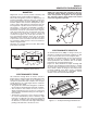
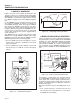
Section 1 GENERATOR FUNDAMENTALS Magnetism Magnetism can be used to produce electricity and electricity can be used to produce magnetism. Much about magnetism cannot be explained by our present knowledge. However, there are certain patterns of behavior that are known. Application of these behavior patterns has led to the development of generators, motors and numerous other devices that utilize magnetism to produce and use electrical energy. See Figure 1-1.
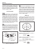
Section 1 GENERATOR FUNDAMENTALS A Simple AC Generator Figure 1-4 shows a very simple AC Generator. The generator consists of a rotating magnetic field called a ROTOR and a stationary coil of wire called a STATOR. The ROTOR is a permanent magnet which consists of a SOUTH magnetic pole and a NORTH magnetic pole. As the MOTOR turns, its magnetic field cuts across the stationary STATOR. A voltage is induced Into the STATOR windings.
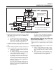
Section 1 GENERATOR FUNDAMENTALS STATOR POWER WINDING ENGINE DIRECT DRIVE STATOR POWER WINDING FIELD BOOST FROM START/STOP RELAY (SSR) ROTOR VOLTAGE REGULATOR BCR2 STATOR BATTERY CHARGE WINDING BCR1 12V DC OUTLET CB1 STATOR DPE WINDING 10A STATOR BATTERY CHARGE WINDING CB2 BCR1 & BCR2 = BATTERY CHARGE RECTIFIER CB2 = EXCITATION CIRCUIT BREAKER Figure 1-7. – Generator Operating Diagram 2.
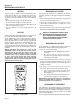
Section 2 MEASURING ELECTRICITY Meters Measuring AC Voltage Devices used to measure electrical properties are called meters. Meters are available that allow one to measure (a) AC voltage, (b) DC voltage, (c) AC frequency, and (d) resistance in ohms. The following apply: • To measure AC voltage, use an AC voltmeter. • To measure DC voltage, use a DC voltmeter. • Use a frequency meter to measure AC frequency in “Hertz” or “cycles per second”.. • Use an ohmmeter to read circuit resistance, in “ohms”.
Section 2 MEASURING ELECTRICITY engine speed governor. For models rated 60 Hertz, the governor is generally set to maintain a no-load frequency of about 62 Hertz with a corresponding output voltage of about 124 volts AC line-to-neutral. Engine speed and frequency at no-load are set slightly high to prevent excessive rpm and frequency droop under heavy electrical loading. Measuring Current Clamp-on: To read the current flow, in AMPERES, a clamp-on ammeter may be used.
Section 2 MEASURING ELECTRICITY Component testing may require a specific resistance value or a test for INFINITY or CONTINUITY. Infinity is an OPEN condition between two electrical points, which would read as no resistance on a VOM. Continuity is a CLOSED condition between two electrical points, which would be indicated as very low resistance or “ZERO” on a VOM. Electrical Units AMPERE: The rate of electron flow in a circuit is represented by the AMPERE.
Section 3 DESCRIPTION & COMPONENTS Introduction The AC Generator The generator revolving field (rotor) is driven by an air-cooled engine at about 3600 rpm. The generator may be used to supply electrical power for the operation of 120 and/or 240 volts, 1-phase, 60 Hz, AC loads. Figure 3-1 shows the major components of the AC generator. Engine-Generator Drive System The generator revolving field is driven by an aircooled, horizontal crankshaft engine.
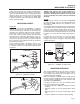
Section 3 DESCRIPTION & COMPONENTS Wire 4 connects to the positive (+) brush and Wire 0 to the negative (-) brush. Wire 0 connects to frame ground. Rectified and regulated excitation current, as well as current from a field boost circuit, are delivered to the rotor windings via Wire 4, and the positive (+) brush and slip ring. The excitation and field boost current passes through the windings and to frame ground via the negative (-) slip ring and brush, and Wire 0.
Section 3 DESCRIPTION & COMPONENTS 162 2 Figure 3-7. – Typical Voltage Regulator Found on 17.5 Units Figure 3-5. – Excitation Circuit Breaker VOLTAGE REGULATOR: A typical Voltage Regulator is shown in Figure 3-6 (12.5 & 15 kW Units) or Figure 3-7 (17.5 kW Units). Unregulated AC output from the stator excitation winding is delivered to the regulator’s DPE terminals, via Wire 2, the Excitation Circuit Breaker and Wire 162, and Wire 6.
Section 3 DESCRIPTION & COMPONENTS with a 62 Hz AC frequency (62 Hz equals 3720 rpm). At the stated no-load frequency, adjust to obtain a line-to-line AC voltage of about 252 volts. Circuit Breakers: Each individual outlet on the generator is protected by a circuit breaker to prevent overload. Rotor Residual Magnetism The generator revolving field (rotor) may be considered to be a permanent magnet. Some “residual” magnetism is always present in the rotor.
Section 3 DESCRIPTION & COMPONENTS The resulting direct current from the BCR is delivered to the 12 VDC receptacle, via Wire 13A, CB1, and Wire 15A. This receptacle allows the capability to recharge a 12 volt DC storage battery with provided battery charge cables. Insulation Resistance The insulation resistance of stator and rotor windings is a measurement of the integrity of the insulating materials that separate the electrical windings from the generator steel core.
Section 3 DESCRIPTION & COMPONENTS or DPE winding, (c) a center tapped battery charge winding and (d) a 10 Amp center tapped battery charge winding. Insulation tests of the stator consist of (a) testing all windings to ground, (b) testing between isolated windings, and (c) testing between parallel windings. Figure 3-9 is a pictorial representation of the various stator leads on units with air-cooled engine. cleaning and drying, the stator fails the second test, the stator assembly should be replaced. 6.
Section 3 DESCRIPTION & COMPONENTS 3. Repeat Step 1 at Pin Location 8 (Wire 55) and Stator Lead 11. 3. Turn the tester switch OFF. For the following steps (4 through 6) an additional paper clip (or similar item) will be needed: 4. Insert a paper clip into Pin Location 3 (Wire 55A). Connect the red tester probe to the paper clip. Insert additional paper clip into Pin Location 6 (Wire 2). Connect the black tester probe to this paper clip.
Section 4 ENGINE DC CONTROL SYSTEM Printed Circuit Board GENERAL: The printed board is responsible for cranking, startup, running and shutdown operations. The board interconnects with other components of the DC control system to turn them on and off at the proper times. It is powered by fused 12 VDC power from the unit battery. CIRCUIT BOARD CONNECTIONS: The circuit board mounts a 12-pin receptacle (J2) and a 5-pin receptacle (J1).
TERMINAL BOARD (TB1) EXCITATION CIRCUIT BREAKER (CB2) TERMINAL BOARD (TB2) PRINTED CIRCUIT BOARD START STOP RELAY (SSR) VOLTAGE REGULATOR 10 AMP AUTO RESET BREAKER (CB1) DIODE (D1) BATTERY CHARGE RECTIFIERS (BCR1 & BCR2) RESISTOR (R1) CONNECTOR (C1) IDLE CONTROL TRANSFORMERS (ICT) 50 AMP CIRCUIT BREAKER STARTER CONTACTOR RELAY (SCR) CONNECTOR (C2) 10 AMP FUSE (F1) LOCATED IN REAR OF CONTROL PANEL Section 4 ENGINE DC CONTROL SYSTEM Control Panel Component Identification Page 17
Section 4 ENGINE DC CONTROL SYSTEM 44S 55A 77A 11S 66A 2 PIN LOCATION 6 44S PIN LOCATION 1 66A 11S 2 55A 77A C1 FEMALE SIDE PIN LOCATION 7 6 C1 MALE SIDE 55 4 66 0 77 0 4 15 55 66 6 86 0 PIN LOCATION 1 18 167 13 PIN LOCATION 6 PIN LOCATION 12 0 77 86 18 167 15 13 C2 FEMALE SIDE PIN LOCATION 7 14 PIN LOCATION 7 PIN LOCATION 6 C2 MALE SIDE 17 15 0 13 16 86 15B 0 229 PIN LOCATION 12 167 BLK 17 15 0 13 16 PIN LOCATION 7 14 44S 11S 83 BLK TERMINAL BL
NOTES Page 19
Section 4 ENGINE DC CONTROL SYSTEM POWER WINDING 77A BA FIELD DPE WINDING BATTERY CHARGE WINDING 66A 0 55A C1-5 C1-4 44 44S 22 11 C1-3 C1-2 10A BATTERY CHARGE WINDING 77 6 C1-6 4 0 C1-7 C1-11 C1-12 RED C1-9 55 44S 11S I.C.T. 66A C1-8 77A 2 I.C. 66 C1-10 11S C1-1 2 6 4 0 0 44A C.B. 30A I.C.T.
Section 4 ENGINE DC CONTROL SYSTEM 120V DUPLEX 11B 11B 0 22 120/240V 30A TWISTLOK 120/240V 50A 22 22 120V/30A TWISTLOK 120V/30A TWISTLOK TEST 0 RESET BA FIELD 120V GFCI TEST RESET C1-12 0 0 44A 11A 0 44B 22 C.B. 30A C.B. 50A 11 0 11D C.B. 30A C.B. 30A 11 22 C2-12 0 C2-7 14 0 14 FSS C2-5 86 86 0 LOP R1 0 14 0 C2-2 15 15 C2-10 15 15 15 C2-4 167 167 SW1 C2-3 0 14 15 17 0 0 17 17 C2-1 13 15 0 C2-8 18 0 11C D2 18 18 IM1 SP1 F1 22 C.B. 20A 0 44C C.
Section 4 ENGINE DC CONTROL SYSTEM POWER WINDING 77A BA FIELD DPE WINDING BATTERY CHARGE WINDING 66A 0 55A C1-5 C1-4 44 44S 22 11 C1-3 C1-2 10A BATTERY CHARGE WINDING 77 6 C1-6 4 0 C1-7 C1-11 C1-12 RED C1-9 55 44S 11S I.C.T. 66A C1-8 77A 2 I.C. 66 C1-10 11S C1-1 2 6 4 0 0 44A C.B. 30A I.C.T.
Section 4 ENGINE DC CONTROL SYSTEM 120V DUPLEX 11B 11B 0 22 120/240V 30A TWISTLOK 120/240V 50A 22 22 120V/30A TWISTLOK 120V/30A TWISTLOK TEST 0 RESET BA FIELD 120V GFCI TEST RESET C1-12 0 0 44A 11A 0 44B 22 C.B. 30A C.B. 50A 11 0 11D C.B. 30A C.B. 30A C2-7 0 14 FSS C2-5 86 86 0 LOP R1 0 14 0 C2-2 15 15 C2-10 15 15 15 C2-4 167 167 SW1 C2-3 0 17 C2-8 17 C2-1 13 0 0 17 18 15 0 D2 18 18 IM1 SP1 F1 0 44C C.B.
Section 5 TROUBLESHOOTING FLOWCHARTS Introduction The “Flow Charts” in this section may be used in conjunction with the “Diagnostic Tests” of Section 6. Numbered tests in the Flow Charts correspond to identically numbered tests of Section 6. Problems 1 through 5 apply to the AC generator only. Beginning with Problem 5, the engine DC control system is dealt with.
Section 5 TROUBLESHOOTING FLOWCHARTS Problem 2 - Generator Produces Zero Voltage or Residual Voltage (2-12 VAC) TEST 2 - CHECK MAIN CIRCUIT BREAKER TEST 3 - TEST EXCITATION CIRCUIT BREAKER GOOD GOOD -PROCEED BAD -PROCEED, REPLACE AFTER TESTS CONCLUDE RESET TO “ON” OR REPLACE IF BAD A TEST 4 PERFORM FIXED EXCITATION / ROTOR AMP DRAW B TEST 6 - WIRE CONTINUITY C TEST 9 - TEST STATOR BAD GOOD D TEST 12 CHECK BRUSH LEADS BAD BAD GOOD GOOD TEST 7 FIELD BOOST BAD GOOD TEST 11 EXCITATION WIRING R
Section 5 TROUBLESHOOTING FLOWCHARTS Problem 2 - Generator Produces Zero Voltage or Residual Voltage (2-12 VAC) (continued) E TEST 4 PERFORM FIXED EXCITATION / ROTOR AMP DRAW CHECK VOLTMETER FUSES - VERIFY AMP METER FUNCTIONS G REPLACE FUSES - THEN RETEST F TEST 14 CHECK ROTOR ASSEMBLY BAD TEST 9 - TEST STATOR DPE WINDING REPAIR OR REPLACE INSULATION RESISTANCE TEST PAGE 14 GOOD INSULATION RESISTANCE TEST PAGE 13 BAD REPAIR OR REPLACE BAD BAD Problem 3 - Excessive Voltage/Frequency Droop Wh
Section 5 TROUBLESHOOTING FLOWCHARTS Problem 4 - No Battery Charge Output TEST 17 CHECK BATTERY CHARGE OUTPUT BAD TEST 19 CHECK BATTERY CHARGE RECTIFIER GOOD TEST 9 - TEST STATOR BAD BAD GOOD REPLACE FINISHED GOOD INSULATION RESISTANCE TEST PAGE 13 REPAIR OR REPLACE BAD REPAIR OR REPLACE Problem 5 - No 10A Battery Charge Output TEST 18 CHECK 10A BATTERY CHARGE OUTPUT BAD GOOD FINISHED TEST 19 CHECK BATTERY CHARGE RECTIFIER GOOD TEST 20 CHECK 10A CIRCUIT BREAKER BAD BAD REPLACE REPLA
Section 5 TROUBLESHOOTING FLOWCHARTS Problem 6 - Engine Will Not Crank TEST 22 - CHECK BATTERY & CABLES TEST 21 CHECK 10 AMP FUSE FUSE BAD RECHARGE OR REPLACE BATTERY - CLEAN, REPAIR OR REPLACE BAD CABLE(S) BAD REPLACE FUSE FUSE BLOWS GO TO PROBLEM 9 GOOD TEST 23 - CHECK VOLTAGE AT STARTER CONTACTOR TEST 26 - CHECK STARTER CONTACTOR RELAY (SCR) NO VOLTAGE MEASURED BAD 12 VDC MEASURED TEST 24 - CHECK STARTER CONTACTOR REPAIR OR REPLACE WIRING OR SCR BAD TEST 28 - CHECK START-RUN-STOP SWITCH (SW1)
Section 5 TROUBLESHOOTING FLOWCHARTS Problem 7 - Engine Cranks But Will Not Start CHECK FUEL SUPPLY CHECK FUEL SHUTOFF VALVE GOOD GOOD VERIFY THAT IDLE CONTROL SWITCH IS IN THE “OFF” POSITION OFF REPLENISH FUEL SUPPLY ON TURN ON TEST 38 CHECK FUEL PUMP GOOD PULL CHOKE FULL OUT OFF PULL OUT FULL OUT GOOD TEST 29 CHECK SPARK TURN OFF TEST 36 - CHECK FUEL SHUTOFF SOLENOID (FSS) GOOD TEST 30 CHECK SPARK PLUGS BAD BAD BAD REPLACE REPAIR OR REPLACE TEST 37 - CHECK FUEL SHUTOFF SOLENOID VOLT
Section 5 TROUBLESHOOTING FLOWCHARTS Problem 8 - Engine Starts Hard and Runs Rough CHECK FUEL SUPPLY GOOD CHECK CHOKE POSITION AND OPERATION TEST 29 CHECK SPARK GOOD TEST 30 CHECK SPARK PLUG GOOD ENGINE MISS IS APPARENT LOW FUEL GOOD BAD PUSH IN AFTER STARTING REPLACE SPARK PLUG REPLENISH FUEL SUPPLY TEST 38 CHECK FUEL PUMP TEST 35 - CHECK AND ADJUST IGNITION MAGNETOS GOOD TEST 39 - CHECK CARBURETION GOOD TEST 5 - CHECK STEPPER MOTOR CONTROL ADJUST OR REPLACE BAD TEST 40 - CHECK VALVE A
Section 5 TROUBLESHOOTING FLOWCHARTS Problem 10 - 10 Amp Fuse (F1) Blowing FUSE BLOWS WHEN RUNNING TEST 43 - CHECK START STOP RELAY (SSR) FUSE BLOWS UPON INSTALLATION INSTALL NEW 10 AMP FUSE GOOD CHECK FUEL SOLENOID (TEST 47) AND STARTER CONTACTOR RELAY (TEST 44) BAD FUSE IS GOOD BUT BLOWS WHEN PLACED TO START BAD REPLACE GOOD REPLACE TEST 45 - CHECK WIRE 15 VERIFY START-RUN-STOP SWITCH IS WIRED CORRECTLY (SEE FIGURE 6-46, pg.
Section 5 TROUBLESHOOTING FLOWCHARTS Problem 11 - Unit Overspeeds TEST 1 - CHECK NO-LOAD VOLTAGE & FREQUENCY CHECK TO SEE IF RED LED ON CIRCUIT BOARD IS “ON” PRODUCING VOLTAGE NO VOLTAGE OFF GO TO PROBLEM 2 TEST 51 - CHECK WIRES 11S / 44S ON TEST 5 - CHECK STEPPER MOTOR OPERATION GOOD BAD REPLACE CIRCUIT BOARD GOOD BAD REPAIR OR REPLACE Problem 12 - Idle Control “RPM Does Not Decrease” VERIFY THAT THERE IS NO LOAD ON THE GENERATOR TEST 52 - CHECK IDLE CONTROL SWITCH TEST 53 - CHECK IDLE CONTR
Section 6 DIAGNOSTIC TESTS Introduction The “Diagnostic Tests” in this chapter may be performed in conjunction with the “Flow Charts” of Section 5. Test numbers in this chapter correspond to the numbered tests in the “Flow Charts”. Tests 1 through 19 are procedures Involving problems with the generator's AC output voltage and frequency (Problems 1 through 5 in the “Flow Charts”).
Section 6 DIAGNOSTIC TESTS TEST 4 - FIXED EXCITATION TEST/ ROTOR AMP DRAW 20/30A C.B. 00.00 PROCEDURE: *NOTE: If the generator is not producing AC Power, loss of governor control may occur causing an overspeed or extremely high RPM condition. If this condition occurs manually control throttle (60Hz /3600 RPM) to perform test. 1. Unplug the six pin connector at the Voltage Regulator. 2. Disconnect Wire 14 from the Resistor (R1). Figure 6-8.
Section 6 DIAGNOSTIC TESTS 9. Shutdown the generator. 1.5 A 10. Reconnect Wire 2 to the Excitation Circuit Breaker. 11. Connect one meter test lead to Wire 11S located in the six pin connector previously removed from the Voltage Regulator. Connect the other meter test lead to Wire 44S located in the six pin connector previously removed from the Voltage Regulator. See Figure 6-11. Be careful not to damage the pin connectors with the test leads.
Section 6 DIAGNOSTIC TESTS TEST 5 - CHECK STEPPER MOTOR CONTROL PROCEDURE: 1. Remove air cleaner cover to access stepper motor. 2. Physically grab the throttle and verify the stepper motor, linkage and throttle do not bind in any way, if any binding is felt repair or replace components as needed. Some resistance should be felt as the stepper motor moves through it's travel. 3. Physically move the throttle to the closed position by pushing the throttle down as looking from above. a.
Section 6 DIAGNOSTIC TESTS Test 6 - Wire Continuity 86 15B 0 167 229 BLK 83 12.00 BLK PROCEDURE: 1. Set a Voltmeter to measure resistance. 2. Remove the six pin connector from the Voltage Regulator. 3. Connect one meter test lead to Wire 0 in the six pin connector previously removed from the Voltage Regulator. See Figure 611. Be careful not to damage the pin connectors with the test leads. TR2 TERMINAL BLOCK (TB1) TR1 3. Connect the other test lead to the ground terminal in the control panel.
Section 6 DIAGNOSTIC TESTS 16 16 87 15 86 87a OL 14 WIRE 14 REMOVED 17 85 14 30 13 WIRING DIAGRAM R1 87a 30 87 D2 86 85 4 4 Figure 6-13. – Starter Contactor Relay Figure 6-15. – Diode Test Step 5 6. Connect the positive meter test lead to the bottom terminal of the diode (D1). Connect the negative meter test lead to the top of the diode (D1). Approximately 0.5 Volts should be measured. 3.0 vdc 14 .5 vdc R1 14 D2 14 WIRE 14 REMOVED 14 4 4 R1 Figure 6-14.
Section 6 DIAGNOSTIC TESTS 14 WIRE 14 REMOVED 25 ohm 55A 77A 66A 2 PIN LOCATION 6 14 11S 44S PIN LOCATION 1 R1 PIN LOCATION 7 6 55 0 77 66 PIN LOCATION 12 4 D2 4 4 Figure 6-17. – Diode Test Step 9 10. Connect one meter test lead to the top terminal of the resistor (R1). Connect the other meter test lead to the ground terminal. INFINITY or an open condition should be measured. 11.
Section 6 DIAGNOSTIC TESTS 12. Connect the meter test leads across Stator lead 2 (Pin 6) at the C1 connector female side and frame ground. Be careful not to damage the pin connectors with the test leads, use paper clips - do not force probes into connectors. See Figure 6-18. INFINITY should be read. 13. Connect the meter test leads across Stator lead 66 (Pin 9) at the C1 connector female side and frame ground.
Section 6 DIAGNOSTIC TESTS TEST 11 - EXCITATION WIRING PROCEDURE: 1. Set a voltmeter to measure resistance. 2. Disconnect Connector C1. See Page 17 for connector location. 3. Locate the male side of the connector located on the bottom of the control panel. See Figure 6-19. Connect one meter test lead to Pin 6 Wire 2, it may be helpful to connect a small jumper lead to the individual pin. Disconnect Wire 2 from the Excitation Circuit Breaker (CB1). Connect the other meter test lead to Wire 2 .
Section 6 DIAGNOSTIC TESTS * Resistance values in ohms at 20° C. (68° F.). Actual readings may vary depending on ambient temperature. A tolerance of plus or minus 5% is allowed. BRUSHES 3. Connect the positive (+) meter test lead to the positive (+) slip ring, the common (-) test lead to a clean frame ground (such as the Rotor shaft). The meter should read INFINITY. Figure 6-21. – Brush Location 2. Remove Wire 4 from the positive (+) brush terminal. RESULTS: 1. Replace the Rotor if it fails the test. 2.
Section 6 DIAGNOSTIC TESTS 2. If load is within limits, but frequency and voltage still drop excessively, refer back to Flow Chart. TEST 17 - CHECK BATTERY CHARGE OUTPUT PROCEDURE: 1. Disconnect Wire 15 (center terminal) from the Battery Charge Rectifier 2 (BCR2), which is located under BCR1. They are stacked. See Page 17 for BCR2 location. 15 2.0 a 2. Set a voltmeter to measure DC Amperage. Connect the positive (+) test lead to the center terminal of the Battery Charge Rectifier.
Section 6 DIAGNOSTIC TESTS Short to Ground: 4. Set the VOM to measure resistance. Connect the positive (+) test lead to the case housing of the BCR. Connect the negative (-) test lead to an outer terminal. INFINITY should be measured. Now connect the negative test lead to the BCR center terminal. INFINITY should be measured. Next, connect the negative test lead to the remaining outer BCR terminal. Once again INFINITY should be measured. 66 00.
Section 6 DIAGNOSTIC TESTS measure at the battery terminals during cranking. If battery voltage is below 11 volts DC, recharge/replace battery. If battery or cables are still suspected, connect an alternate battery and cables to the generator and retest. 2. Use a battery hydrometer to test the battery for (a) state of charge and (b) condition. Follow the hydrometer manufacturer's instructions carefully. RESULTS: 1. Clean battery posts and cables as necessary. Make sure battery cables are tight. 2.
Section 6 DIAGNOSTIC TESTS 3. A defective Starter Motor switch. 4. Broken, damaged or weak magnets. 5. Starter drive dirty or binding. CHECKING THE PINION: When the Starter Motor is activated, the pinion gear should move and engage the flywheel ring gear. If the pinion does not move normally, inspect the pinion for binding or sticking. PROCEDURE: The battery should have been checked prior to this test and should be fully charged. Set a voltmeter to measure DC voltage (12 VDC).
Section 6 DIAGNOSTIC TESTS CLAMP ON AMP METER STARTER CONTACTOR STARTER MOTOR Figure 6-32. – Tachometer Test Bracket: A starter motor test bracket may be made as shown in Figure 6-33. TACHOMETER METAL STOCK 1/4" THICK STEEL 0.5" 12 VOLT BATTERY VISE 2.625" 0.5" 3.5" 1.
Section 6 DIAGNOSTIC TESTS Ground. 12 VDC should be measured. Reconnect Wire 13 to the SCR. If 12 VDC is NOT measured on Wire 13 Stop Testing and repair or replace Wire 13 between the Starter Contactor (SC) and the Starter Contactor Relay (SCR). Note: Jumper leads may be used if necessary. 4. Set voltmeter to measure resistance. 5. Remove Wire 13, Wire 16, and Wire 17 from the Starter Contactor Relay (SCR) 6. Connect the meter leads across Terminal 87 and Terminal 30 of the SCR. See Figure 6-35. 16 00.
Section x6 xxxxxxxxxxxxxxxxxxxxxxxxxx DIAGNOSTIC TESTS 5. Set voltmeter to measure DC voltage. 6. Remove Wire 15 from the Start-Run-Stop Switch (SW1). Connect the positive meter test lead to Wire 15. Connect the negative meter test lead to frame ground. 12 VDC should be measured. RESULTS: Repair or replace any wiring that did not have continuity. If voltage was not measured in Step 6 repair wiring between the Starter Contactor Relay (SCR) and the Start-Run-Stop Switch (SW1).
Section 6 DIAGNOSTIC TESTS TEST 31 - Remove Wire 18 / Shutdown Lead PROCEDURE: 1. Disconnect Wire 18 from the Stud located above the oil cooler that extends out From the shrouding. 2. Perform Test 29 again checking for Spark. RESULTS: Refer back to Flow Chart. WIRE 18 SHUTDOWN LEAD leads across TEST POINTS B INFINITY should be measured. Connect meter test leads across TEST POINTS C. INFINITY should be measured (See Figure 6-42). If the SSR fails any test replace it. 6. Remove Wire 229 from the SSR.
Section 6 DIAGNOSTIC TESTS 14 18 TEST POINTS C TEST POINTS B TEST POINTS A 15 15 1 2 4 5 6 8 9 10 12 13 15 SSR 3. Connect the positive test lead to Wire 167 at Terminal Block 1 (TB1). Connect the negative meter test lead to frame ground. Place the Start-Run-Stop Switch (SW1) to start. 12 VDC should be measured. If 12 VDC is measured, replace Wire 167 between TB1 and the J2 connector. If 12 VDC is not measured continue testing.
Section 6 DIAGNOSTIC TESTS TEST 34 - TEST START STOP RELAY WIRING PROCEDURE: 1. Set voltmeter to the diode test range. 86 15B 0 229 167 BLK 83 BLK 00.00 2. Disconnect Wire 229 from the Start Stop Relay (SSR). 3. Connect the positive meter test lead to Wire 229 previously removed. Connect the negative meter test lead to frame ground. See Figure 6-47. Place the Start-Run-Stop Switch to the start position. The meter should read approximately 1.0 VDC. If the correct voltage is indicated, stop testing.
Section 6 DIAGNOSTIC TESTS 9. Now check the flywheel magnet by holding a screwdriver at the extreme end of its handle and with its point down. When the tip of the screwdriver is moved to within 3/4 inch (19mm) of the magnet, the blade should be pulled in against the magnet. 10. Now check the flywheel key. The flywheel’s taper is locked on the crankshaft taper by the torque of the flywheel nut. A keyway is provided for alignment only and theoretically carries no load.
Section 6 DIAGNOSTIC TESTS PROCEDURE: 1. Remove the fuel line from the fuel filter on the inlet side of the carburetor. Use a suitable catch can to catch fuel. 2. Crank the engine over, fuel should flow from the fuel line. If fuel does not flow, verify that fuel is available to the pump. If fuel is available to the pump inspect the fuel filter, pulse line, and or replace the fuel pump. RESULTS: Refer to flow chart. 5.
Section 6 DIAGNOSTIC TESTS TORQUE SPECIFICATION ROCKER ARM JAM NUT 168 inch-pounds (19 Nm) CROW'S FOOT 5. Attach cylinder leak down tester adapter to spark plug hole. 6. Connect an air source of at least 90 psi to the leak down tester. 7. Adjust the regulated pressure on the gauge to 80 psi. 8. Read the right hand gauge on the tester for cylinder pressure. 20 percent leakage is normally acceptable. Use good judgement, and listen for air escaping at the carburetor, the exhaust, and the crankcase breather.
Section 6 DIAGNOSTIC TESTS • Loose cylinder head bolts. • Failed cylinder head gasket. • Burned valves or valve seats. • Insufficient valve clearance. • Warped cylinder head. • Warped valve stem. • Worn or broken piston ring(s). • Worn or damaged cylinder bore. • Broken connecting rod. • Worn valve seats or valves. • Worn valve guides. NOTE: Refer to Engine Service manual No. 0F6923 for further engine service information.
Section 6 DIAGNOSTIC TESTS RESULTS: 1. If the SSR measures continuity or zero resistance it is shorted to ground and should be replaced. RESULTS: 1. If the SCR measures continuity or zero resistance it is shorted to ground and should be replaced. 2. If the SSR resistance is correct refer to flow chart. 2. If the SCR resistance is correct refer to flow chart. 15 TEST 45 - CHECK WIRE 15 CIRCUIT 18 14 1 2 5 6 4 8 9 10 12 100 ohm 15B 2. Remove the Fuse (F1). 0 13 15 3.
Section 6 DIAGNOSTIC TESTS RESULTS: 1. If continuity or zero was measured in Step 3 or Step 4 replace the FSS. RESULTS: 1. If continuity was measured in Step 2 but not in Step 3, replace the printed circuit board. 2. (Units without Hourmeter) If correct resistance was measured refer to flow chart, repair or replace Wire 14 between the FSS and Resistor (R1). 2. If continuity was measured in Step 3, Wire 15B is shorted to ground, repair or replace Wire 15B between the SSR and printed circuit board. 3.
Section 6 DIAGNOSTIC TESTS Connect one meter test lead to pin location J2-10 Wire 44S of the connector just removed. Be careful not to damage the pin connectors with the test leads. Connect the other meter test lead to Wire 44S at Terminal Block 2 (TB2). CONTINUITY should be measured. 3. Connect one meter test lead to pin location J2-12 Wire 11S. Be careful not to damage the pin connectors with the test leads. Connect the other meter test lead to Wire 11S at Terminal Block 2 (TB2).
Section 6 DIAGNOSTIC TESTS 7. Apply a light load to the generator, such as a electric drill. 00.00 SW2 8. When the drill is activated measure the voltage output. The AC voltage should measure around 1-2 VAC. RESULTS: Refer back to flow chart. 83 BLK BLK 0 86 15B 0 J2-1 167 229 100 ohm 83 J2-12 TR2 TERMINAL BLOCK (TB1) J2 HARNESS CONNECTOR MAKE SURE THE TEST PROBE CONNECTOR IS MAKING CONTACT WITH THE CONNECTOR. DOUBLE CHECK TO MAKE SURE THAT THE TIP IS SHARP. Figure 6-60.
Section 6 DIAGNOSTIC TESTS PROCEDURE: 1. Set a voltmeter to measure resistance. 86 2. Disconnect the J2 connector from the printed circuit board. 3. Connect one meter test lead to Wire TR2 at Terminal Block 1 (TB1). See Figure 6-62. Connect the other meter test lead to pin location J2-6 on the J2 Connector previously removed. Be careful not to damage the pin connectors with the test leads. Continuity should be measured. 4. Connect one meter test lead to Wire TR1 at Terminal Block 1 (TB1).
Section 7 DISASSEMBLY AND EXPLODED VIEWS Major Disassembly Stator, Rotor, and Engine removal. Reference Figures A and B on Pages 68-71 for component location. 1. Disconnect and remove the battery (Figure B, Item #15) from the generator. 2. Remove Fuel Tank (Figure B, Item #4). Use proper safety precautions when handling gasoline. Figure 7-3. – Control Panel Removed Figure 7-1. – Fuel Tank Removed 3. Remove Control Panel.
Section 7 DISASSEMBLY AND EXPLODED VIEWS 6. Remove Stator. Disconnect Wire 4 and Wire 0 from the brush assembly, Figure A, Item 21. Remove the brush assembly. Remove the four stator hold down bolts, Figure A, Item 12. Lift the rear end of the alternator up to clear the muffler frame from the rubber alternator mount, place a 2x4 under the front bearing carrier for support. Using a rubber mallet carefully remove the rear bearing carrier, Figure A, Item 4.
Page 68 8 39 14 38 24 23 11 46 21 12 33 13 31 4 9 31 32 34 17 28 42 37 43 44 15 3 35 5 39 40 2 41 1 7 30 19 6 40 32 25 19 32 10 17 20 22 30 36 31 16 24 10 26 29 32 31 28 27 28 18 28 10 45 29 Section 7 DISASSEMBLY AND EXPLODED VIEWS Generator – Figure A
Section 7 DISASSEMBLY AND EXPLODED VIEWS ITEM QTY. 1 1 2 DESCRIPTION ITEM QTY. DESCRIPTION ADAPTOR, ENGINE 24 5 WASHER LOCK 3/8 1 STATOR 25 4 SCREW HHC 3/8-16 X 1-1/4 G5 3 1 ASSEMBLY, ROTOR W/FAN 26 4 WASHER FLAT 3/8-M10 ZINC 4 1 CARRIER, REAR BEARING 27 4 SCREW HHC M8-1.25 X 50 G8.8 5 1 EXHAUST MANIFOLD 28 21 WASHER FLAT 5/16 ZINC 6 1 MUFFLER 29 4 NUT LOCK HEX M8-1.25 NYLON INSERT 7 1 GASKET, EXHAUST 30 7 SCREW HHC M6-1.
Section 7 DISASSEMBLY AND EXPLODED VIEWS Frame, Handle & Wheels – Figure B 47 6 5 2 44 7 45 8 25 48 9 11 12 13 49 1 23 4 3 43 POWER WIRE TO ENGINE 50 10 14 15 46 37 Detail of Battery Tray 33 7 16 17 35 7 6 36 18 17 19 31 41 40 26 39 32 29/51 17 29 20 5 34 21 6 7 52 28 22 24 42 7 26 6 36 CONTROL PANEL 39 38 Page 70 30 27
Section 7 DISASSEMBLY AND EXPLODED VIEWS ITEM QTY. DESCRIPTION 1 4 SCREW HHC M6-1.0 X 55 2 4 RUBBER TANK MOUNT 3 1 CAP, FUEL WITH GAUGE & VENT 4 1 KIT, FUEL TANK ITEM QTY. DESCRIPTION 28 1 AXLE, 3/4”DIA X 30” (15 kW) AXLE, 3/4”DIA X 27.25” (12.5 kW) 29 2 4 WASHER FLAT 3/4” (15 kW) WASHER FLAT 3/4” (12.5 kW) 30 2 12.3” PNEUM WHEEL 3/4” AXLE (15 kW) 10” PNEUM WHEEL 3/4” AXLE (12.5 kW) 5 4 NUT HEX M8-1.
Section 8 ELECTRICAL DATA Wiring Diagram 12.5 & 15 kW (Units Without Hourmeter) – Drawing No. 0E0228 22 120V/30A 120V/30A TWISTLOK TWISTLOK 0 22 0 WHITE 22 4 3 LINE 5 0 0 WHITE LOAD WHITE 3 0 1 HOT 0 22 2 HOT 22 22 HOT G HOT G WHITE X 1 22 120V/20A GFCI 22 WHITE WHITE 120V/20A DUPLEX 120/240V 50A OUTLET 120/240V 30A TWISTLOK G GREEN 2 22 4 WHITE Y 0 5 0 22 0 44C 22 0 44D 22 0 0 22 11A 22 0 0 22 22 22 44B 11B 11C 11D 30A C.B. 30A C.B.
Section 8 ELECTRICAL DATA 120/240V 50A OUTLET 40V STLOK 0 0 G GREEN Y X IDLE CONTROL TRANSFORMERS 22 WHITE Y STATOR 0 11 22 22 11 22 11 11A 22 0 44 A B. 44 44S 2 77A 66A 3 11 44 55A 1 44 44 11 A B. 11S RED 11 11 44 22 44 44A 44 ON OFF 50A C.B.
Section 8 ELECTRICAL DATA Electrical Schematic 12.5 & 15 kW (Units Without Hourmeter) – Drawing No. 0E0229-A POWER WINDING BA FIELD DPE WINDING BATTERY CHARGE WINDING 77A 66A 55A C1-5 C1-4 44 44S 22 11 C1-3 10A BATTERY CHARGE WINDING C1-6 4 0 C1-7 C1-11 C1-12 RED C1-9 55 6 I.C. 66 44S 11S I.C.T. 66A C1-8 77A 2 C1-1 C1-2 77 C1-10 11S 2 6 4 0 C.B. 30A I.C.T.
Section 8 ELECTRICAL DATA 120V DUPLEX 11B 0 -11 11B 22 120/240V 30A TWISTLOK 120/240V 50A 22 22 120V/30A TWISTLOK 120V/30A TWISTLOK TEST 0 RESET BA FIELD 120V GFCI TEST RESET C1-12 0 0 44A 11A 0 44B 22 C.B. 30A 11 C.B. 50A 11 22 0 C.B. 30A 11 22 0 11D C.B.
Section 8 ELECTRICAL DATA Wiring Diagram 12.5 & 15 kW (Units With Hourmeter) – Drawing No. 0D4609-D 22 120V/30A 120V/30A TWISTLOK TWISTLOK 0 22 0 WHITE 3 0 22 4 3 LINE 5 0 0 WHITE LOAD WHITE 0 1 HOT 22 HOT 22 22 2 HOT G HOT G WHITE X 1 22 120V/20A GFCI 22 WHITE WHITE 120V/20A DUPLEX 120/240V 50A OUTLET 120/240V 30A TWISTLOK G GREEN 2 22 4 WHITE Y 0 5 0 22 0 44C 22 0 44D 22 0 0 22 11A 22 0 0 22 22 22 44B 11B 11C 11D 30A C.B. 30A C.B.
Section 8 ELECTRICAL DATA 120/240V 50A OUTLET 0V TLOK 0 0 G GREEN Y X Y IDLE CONTROL TRANSFORMERS 22 WHITE STATOR 0 11 22 22 11 22 11 11A 22 0 44 44 44 44S 2 77A 66A 3 11 44 55A 1 44 44 11 11S RED 11 44 22 44 44A 11 ON OFF 50A C.B.
Section 8 ELECTRICAL DATA Electrical Schematic 12.5 & 15 kW (Units With Hourmeter) – Drawing No. 0D6297-A POWER WINDING 77A BA FIELD DPE WINDING BATTERY CHARGE WINDING 66A 55A C1-5 C1-4 44 44S 22 11 C1-3 10A BATTERY CHARGE WINDING C1-6 4 0 C1-7 C1-11 C1-12 RED C1-9 55 6 I.C. 66 44S 11S I.C.T. 66A C1-8 77A 2 C1-1 C1-2 77 C1-10 11S 2 6 4 0 C.B. 30A I.C.T.
Section 8 ELECTRICAL DATA 120V DUPLEX 11B 22 120/240V 30A TWISTLOK 120/240V 50A 0 C1-11 11B 22 22 120V/30A TWISTLOK 120V/30A TWISTLOK TEST 0 120V GFCI RESET BA FIELD TEST RESET C1-12 0 0 44A 11A 0 44B 22 C.B. 30A 11 C.B. 30A 0 44D 22 C.B. 30A 11 22 0 11D C.B. 30A C.B. 50A 11 22 0 11C C.B. 20A 22 0 44C C.B.
Section 8 ELECTRICAL DATA Wiring Diagram 17.5 kW – Drawing No. 0G0731 22 120V/30A 120V/20A DUPLEX 120V/30A TWISTLOK TWISTLOK 22 2 1 LOAD WHITE G HOT HOT G G GREEN 2 3 LINE WHITE WHITE 22 4 HOT 3 0 HOT 0 5 44D 11D 0 0 11C 0 WHITE Y 22 4 5 44C 0 22 0 22 22 22 0 0 0 22 0 11A 22 0 22 22 11B 44B 30A C.B. 44A 44 44 44 44 11 11 0 44D 30A C.B. 11D 30A C.B. 11C 20A C.B. 44C 20A C.B. 44 30A 11B C.B.
Section 8 ELECTRICAL DATA 22 IDLE CONTROL TRANSFORMERS STATOR 22 11 11 22 11 22 44 11S 22S RED 11 44 44 55A 1 44 2 3 4 22S 83 167 229 77A 66A 11S 6 2 5 55A 55 6 66 7 15B BLK BLK 0 86 9 55 2 TB1 77 CLOSEST TO BEARING 8 BA 10 TB2 11 4 12 0 PIN # 83 229 167 0 15B 86 CB1 ON/OFF IDLE CONTROL SWITCH 12 11 10 9 8 7 6 5 4 3 2 11S 1 J2 55A 22S 162 4 55 0 77A 66A 77 66 6 ELECTRONIC GOVERNOR / ENGINE SHUTDOWN P.C.B.
Section 8 ELECTRICAL DATA Electrical Schematic 17.5 kW – Drawing No. 0G0733 POWER WINDING 77A 55A C1-5 66A 11S C1-4 C1-3 11 22S C1-1 44 C1-2 2 6 C1-6 22 10A BATTERY CHARGE WINDING BA FIELD DPE WINDING BATTERY CHARGE WINDING 4 C1-7 0 C1-11 C1-12 I.C. RED 77 55 C1-10 66 I.C.T. C1-9 C1-8 66A 77 66 22S 11S 22 I.C.T.
Section 8 ELECTRICAL DATA Wiring Diagram, 17.5 kW Manual Transfer Switch – Drawing No.
Section 8 ELECTRICAL DATA INTERCONNECTION DRAWING – 17.
NOTES Page 85
Section 9 SPECIFICATIONS & CHARTS GENERATOR SPECIFICATIONS MODEL Model # GPS 12500 GPS 15000 GPS 17500 004582 004451 004583 004987 004986 005308 005209 Rated Max. Power 12.5 kW 15.0 kW 17.5 kW Surge Power 18.75 kW 22.5 kW 26.25 kW 120/240 120/240 120/240 Current @ 240V 52.0 Amps 62.5 Amps 72.9 Amps Current @ 120V 104.0 Amps 125.0 Amps 145.
Section 9 SPECIFICATIONS & CHARTS Torque Specifications Flywheel Nut Cylinder Head Bolts Valve Cover Bolts Rocker Arm Jam Nut Ignition Coil Intake Manifold Exhaust Manifold Stator Bolt Rotor Bolt Spark Plug Starter Bracket To Block 150 ft. lbs. 22 ft. lbs. 4.8-5.5 ft. lbs. 14 ft. lbs. 9 ft. lbs. 14 ft. lbs. 14 ft. lbs. 12 ft. lbs. 30 ft. lbs. 15 ft. lbs. 18 ft. lbs. TRIM Torque Specifications M3-.
0F7713 Cover-rev.qxd 7/5/2006 4:18 PM Page 1 PORTABLES MODELS: 4451 & 4986 (12,500 Watt) 4582 & 4987 (15,000 Watt) 4583 (17,500 Watt) 5209 (15,000 Watt) 5308 (17,500 Watt) PO BOX 297 • WHITEWATER, WI 53190 www.guardiangenerators.com DIAGNOSTIC REPAIR MANUAL ULTRA SOURCE PORTABLE GENERATOR P/N OF7713 REV. A Printed in the USA 6.06 www.guardiangenerators.