AIR-COOLED DIAGNOSTIC REPAIR MANUAL AUTOMATIC HOME STANDBY GENERATORS Models: 4389, 4758 (6 kW NG, 7 kW LP) 4456, 4759 (12 kW NG, 12 kW LP) 4390, 4760 (13 kW, 15 kW LP) Visit us online at www.guardiangenerators.
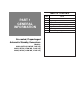
TABLE OF CONTENTS PART TITLE Specifications DIAGNOSTIC REPAIR MANUAL Air-cooled, Prepackaged Automatic Standby Generators Models: 04389, 04758 (6 kW NG, 7 kW LP) 04456, 04759 (12 kW NG, 12 kW LP) 04390, 04760 (13 kW NG, 15 kW LP) 1 General Information 2 AC Generators 3 V-Type Prepackaged Transfer Switches 4 DC Control 5 Operational Tests and Adjustments 6 Disassembly 7 Electrical Data
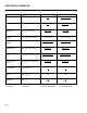
ELECTRICAL FORMULAS TO FIND KNOWN VALUES 1-PHASE 3-PHASE KILOWATTS (kW) Volts, Current, Power Factor ExI 1000 E x I x 1.73 x PF 1000 KVA Volts, Current ExI 1000 E x I x 1.73 1000 AMPERES kW, Volts, Power Factor kW x 1000 E kW x 1000 E x 1.73 x PF WATTS Volts, Amps, Power Factor Volts x Amps E x I x 1.73 x PF NO. OF ROTOR POLES Frequency, RPM 2 x 60 x Frequency RPM 2 x 60 x frequency RPM FREQUENCY RPM, No. of Rotor Poles RPM x Poles 2 x 60 RPM x Poles 2 x 60 RPM Frequency, No.
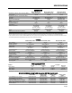
SPECIFICATIONS GENERATOR Rated Max. Continuous Power Capacity (Watts*) Rated Voltage Rated Max. Continuous Load Current (Amps) 120 Volts** 240 Volts Main Line Circuit Breaker Phase Number of Rotor Poles Rated AC Frequency Power Factor Battery Requirement Weight Output Sound Level @ 23 ft (7m) at full load Normal Operating Range Models 04389, 04758 6,000 NG/7,000 LP 120/240 Models 04456, 04759 12,000 NG/12,000 LP 120/240 Model 04390, 04760 13,000 NG/15,000 LP 120/240 50.0 NG/58.3 LP 25.0 NG/29.
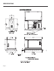
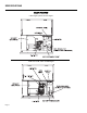
SPECIFICATIONS MOUNTING DIMENSIONS Page 3
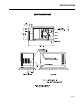
SPECIFICATIONS MOUNTING DIMENSIONS Page 4
SPECIFICATIONS MAJOR FEATURES 7 kW, Single Cylinder GH-410 Engine 12 kW and 15 kW, V-twin GT-990 Engine Page 5
TABLE OF CONTENTS PART PART 1 GENERAL INFORMATION Air-cooled, Prepackaged Automatic Standby Generators Models: 04389, 04758 (6 kW NG, 7 kW LP) 04456, 04759 (12 kW NG, 12 kW LP) 04390, 04760 (13 kW NG, 15 kW LP) TITLE 1.1 Generator Identification 1.2 Prepackaged Installation Basics 1.3 Preparation Before Use 1.4 Testing, Cleaning and Drying 1.5 Engine-Generator Protective Devices 1.6 Operating Instructions 1.
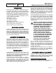
SECTION 1.1 GENERATOR IDENTIFICATION PART 1 GENERAL INFORMATION INTRODUCTION This Diagnostic Repair Manual has been prepared especially for the purpose of familiarizing service personnel with the testing, troubleshooting and repair of air-cooled, prepackaged automatic standby generators. Every effort has been expended to ensure that information and instructions in the manual are both accurate and current.
GENERAL INFORMATION PART 1 INTRODUCTION Information in this section is provided so that the service technician will have a basic knowledge of installation requirements for prepackaged home standby systems. Problems that arise are often related to poor or unauthorized installation practices. A typical prepackaged home standby electric system is shown in Figure 1 (next page). Installation of such a system includes the following: ❏ Selecting a Location ❏ Grounding the generator. ❏ Providing a fuel supply.
SECTION 1.2 PREPACKAGED INSTALLATION BASICS PART 1 Figure 1. Typical Prepackaged Installation Page 1.
GENERAL INFORMATION SECTION 1.2 PART 1 PREPACKAGED INSTALLATION BASICS POWER SOURCE AND LOAD LINES SYSTEM CONTROL INTERCONNECTIONS The utility power supply lines, the standby (generator) supply lines, and electrical load lines must all be connected to the proper terminal lugs in the transfer switch. The following rules apply:In 1-phase systems with a 2-pole transfer switch, connect the two utility source hot lines to Transfer Switch Terminal Lugs N1 and N2.
SECTION 1.3 PREPARATION BEFORE USE PART 1 GENERAL INFORMATION GENERAL ENGINE OIL RECOMMENDATIONS The installer must ensure that the home standby generator has been properly installed. The system must be inspected carefully following installation. All applicable codes, standards and regulations pertaining to such installations must be strictly complied with. In addition, regulations established by the Occupational Safety and Health Administration (OSHA) must be complied with.
GENERAL INFORMATION SECTION 1.4 PART 1 TESTING, CLEANING AND DRYING VISUAL INSPECTION When it becomes necessary to test or troubleshoot a generator, it is a good practice to complete a thorough visual inspection. Remove the access covers and look closely for any obvious problems. Look for the following: ❏ Burned or broken wires, broken wire connectors, damaged mounting brackets, etc. ❏ Loose or frayed wiring insulation, loose or dirty connections. ❏ Check that all wiring is well clear of rotating parts.
SECTION 1.4 TESTING, CLEANING AND DRYING PART 1 GENERAL INFORMATION 2. Before reading a DC voltage, always set the meter to a higher voltage scale than the anticipated reading. if in doubt, start at the highest scale and adjust the scale downward until correct readings are obtained. 3. The design of some meters is based on the "current flow" theory while others are based on the "electron flow" theory. a. b.
GENERAL INFORMATION PART 1 SECTION 1.4 TESTING, CLEANING AND DRYING If proper procedures are used, the following conditions can be detected using a VOM: ❏ A "short-to-ground" condition in any stator or rotor winding. ❏ Shorting together of any two parallel stator windings. ❏ Shorting together of any two isolated stator windings. ❏ An open condition in any stator or rotor winding. Component testing may require a specific resistance value or a test for INFINITY or CONTINUITY.
SECTION 1.4 PART 1 TESTING, CLEANING AND DRYING INSULATION RESISTANCE The insulation resistance of stator and rotor windings is a measurement of the integrity of the insulating materials that separate the electrical windings from the generator steel core. This resistance can degrade over time or due to such contaminants as dust, dirt, oil, grease and especially moisture. In most cases, failures of stator and rotor windings is due to a breakdown in the insulation.
GENERAL INFORMATION PART 1 TESTING ALL STATOR WINDINGS TO GROUND: 1. Disconnect stator output leads 11 and 44 from the generator main line circuit breaker. 2. Remove stator output leads 22 and 33 from the neutral connection and separate the two leads. 3. Disconnect C2 connector from the side of the control panel. The C2 connector is the closest to the back panel. SECTION 1.4 TESTING, CLEANING AND DRYING 6. Now proceed to the C2 connector. Each winding will be individually tested for a short to ground.
SECTION 1.4 TESTING, CLEANING AND DRYING 5. Insert a large paper clip into Pin Location No. 1 (Wire 77). Connect the red tester probe to the paper clip. Connect the black tester probe to Stator Lead 33. Refer to Steps 5a through 5c of “TESTING ALL STATOR WINDINGS TO GROUND” on the previous page. 6. Repeat Step 5 at Pin Location 3 (Wire 66A) and Stator Lead 33. PART 1 GENERAL INFORMATION 6. Observe the breakdown lamp, then turn the tester switch OFF. DO NOT APPLY VOLTAGE LONGER THAN ONE (1) SECOND.
GENERAL INFORMATION PART 1 GENERAL SECTION 1.5 ENGINE-GENERATOR PROTECTIVE DEVICES above. Standby electric power generators will often run unattended for long periods of time. Such operating parameters as (a) engine oil pressure, (b) engine temperature, (c) engine operating speed, and (d) engine cranking and startup are not monitored by an operator during automatic operation.
SECTION 1.6 PART 1 OPERATING INSTRUCTIONS CONTROL PANEL GENERAL: See Figure 1. The front face of this panel mounts (a) an hourmeter, (b) an AUTO-OFF-MANUAL switch ,(c) a 15 amp fuse, (d) a 5 amp fuse, (e) a set exercise switch and (f) the protection systems. HOURMETER: Equipped on some models only. The hourmeter indicates engine-generator operating-time, in hours and tenths of hours. Use the meter in conjunction with the periodic maintenance schedule for the applicable generator set.
GENERAL INFORMATION PART 1 THE SET EXERCISE SWITCH: The air-cooled, prepackaged automatic standby generator will start and exercise once every seven (7) days, on a day and at a time of day selected by the owner or operator. The set exercise time switch is provided to select the day and time of day for system exercise. See Page 5.1-3 ("The 7-Day Exercise Cycle") for instructions on how to set exercise time. DANGER: THE GENERATOR WILL CRANK AND START WHEN THE SET EXERCISE TIME SWITCH IS SET TO "ON".
SECTION 1.6 OPERATING INSTRUCTIONS 7. Set the generator main line circuit breaker to its "On" or "Closed" position. The generator now powers the electrical loads. MANUAL SHUTDOWN AND RETRANSFER BACK TO "UTILITY" To shut the generator down and retransfer electrical loads back to the UTILITY position, proceed as follows: 1. Set the generator main line circuit breaker to its OFF or "Open" position. 2. Let the generator run at no-load for a few minutes, to cool. 3.
GENERAL INFORMATION PART 1 INTRODUCTION When the prepackaged generator is installed in conjunction with a prepackaged transfer switch, either manual or automatic operation is possible. Manual transfer and engine startup, as well as manual shutdown and retransfer are covered in Section 1.6. Selection of fully automatic operation is also discussed in that section. This section will provide a step-by-step description of the sequence of events that will occur during automatic operation of the system.
SECTION 1.7 AUTOMATIC OPERATING PARAMETERS PART 1 GENERAL INFORMATION AUTOMATIC OPERATING SEQUENCES CHART SEQ. CONDITION ACTION SENSOR, TIMER OR OTHER 1 Utility source voltage is available. No action Voltage Dropout Sensor on circuit circuit board. 2 Utility voltage dropout below 60% of rated voltage occurs. A 15-second timer on circuit board turns on. Voltage Dropout Sensor and 15 second timer on circuit board. 3 Utility voltage is still below 60% of rated voltage.
TABLE OF CONTENTS PART PART 2 AC GENERATORS Air-cooled, Prepackaged Automatic Standby Generators Models: 04389, 04758 (6 kW NG, 7 kW LP) 04456, 04759 (12 kW NG, 12 kW LP) 04390, 04760 (13 kW NG, 15 kW LP) TITLE 2.1 Description and Components 2.2 Operational Analysis 2.3 Troubleshooting Flow Charts 2.
SECTION 2.1 PART 2 DESCRIPTION & COMPONENTS INTRODUCTION The air-cooled, pre-packaged automatic standby system is an easy to install, fully enclosed and selfsufficient electric power system. It is designed especially for homeowners, but may be used in other applications as well. On occurrence of a utility power failure, this high performance system will (a) crank and start automatically, and (b) automatically transfer electrical loads to generator AC output.
AC GENERATORS PART 2 SECTION 2.1 DESCRIPTION & COMPONENTS Wire 4 connects to the positive (+) brush and Wire 0 to the negative (-) brush. Wire 0 connects to frame ground. Rectified and regulated excitation current, as well as current from a field boost circuit, are delivered to the rotor windings via Wire 4, and the positive (+) brush and slip ring. The excitation and field boost current passes through the windings and to frame ground via the negative (-) slip ring and brush, and Wire 0.
SECTION 2.1 DESCRIPTION & COMPONENTS PART 2 AC GENERATORS Figure 5. Excitation Circuit Breaker VOLTAGE REGULATOR: A typical voltage regulator is shown in Figure 6. Unregulated AC output from the stator excitation winding is delivered to the regulator’s DPE terminals, via Wire 2, the excitation circuit breaker, Wire 162, and Wire 6. The voltage regulator rectifies that current and, based on stator AC power winding sensing, regulates it.
AC GENERATORS SECTION 2.2 PART 2 ROTOR RESIDUAL MAGNETISM The generator revolving field (rotor) may be considered to be a permanent magnet. Some ’residual" magnetism is always present in the rotor. This residual magnetism is sufficient to induce a voltage into the stator AC power windings that is approximately 2-12 volts AC. OPERATIONAL ANALYSIS Field boost voltage is reduced from that of battery voltage by the resistor action and, when read with a DC voltmeter, will be approximately 9 or 10 volts DC.
SECTION 2.2 OPERATIONAL ANALYSIS OPERATION STARTUP: When the engine is started, residual plus field boost magnetism from the rotor induces a voltage into (a) the stator AC power windings, (b) the stator excitation or DPE windings, (c) the stator battery charge, and (d) engine run winding. In an "on-speed" condition, residual plus field boost magnetism are capable of creating approximately one-half the unit’s rated voltage.
AC GENERATORS SECTION 2.3 PART 2 TROUBLESHOOTING FLOWCHARTS GENERAL Use the Flow Charts in conjunction with the detailed instructions in Section 2.4. Test numbers used in the flow charts correspond to the numbered tests in Section 2.4. The first step in using the flow charts is to correctly identify the problem. Once that has been done, locate the problem on the following pages. For best results, perform all tests in the exact sequence shown in the flow charts. Page 2.
SECTION 2.3 TROUBLESHOOTING FLOWCHARTS Page 2.
AC GENERATORS PART 2 SECTION 2.3 TROUBLESHOOTING FLOWCHARTS Page 2.
SECTION 2.3 TROUBLESHOOTING FLOWCHARTS Page 2.
AC GENERATORS SECTION 2.4 PART 2 INTRODUCTION This section is provided to familiarize the service technician with acceptable procedures for the testing and evaluation of various problems that could be encountered on prepackaged standby generators with air-cooled engine. Use this section of the manual in conjunction with Section 2.3, "Troubleshooting Flow Charts". The numbered tests in this section correspond with those of Section 2.3.
SECTION 2.4 PART 2 DIAGNOSTIC TESTS TEST 2- CHECK AC OUTPUT VOLTAGE DISCUSSION: A volt-ohm-milliammeter (VOM) may be used to check the generator output voltage. Output voltage may be checked at the unit’s main circuit breaker terminals. Refer to the unit’s DATA PLATE for rated line-to-line and line-to-neutral voltages. DANGER: USE EXTREME CAUTION DURING THIS TEST. THE GENERATOR WILL BE RUNNING. HIGH AND DANGEROUS VOLTAGES WILL BE PRESENT AT THE TEST TERMINALS.
SECTION 2.4 PART 2 Zero Current Draw Test 10 Test 7 Test 7 Test 8 Test 10 Test 7 Test 8 MATCH RESULTS WITH LETTER AND REFER TO FLOW CHART ON PAGE 2.3-1 1 & 2.3-2 2 “Problem 1” Test 5 Zero Current Draw 0.91-1.06A 0.80A 0.64A 0.71-0.82A Above 1.5A Above 1.3A Above 1.1A Above 1.3A Zero Current Draw 0.91-1.06A 0.80A 0.64A 0.71-0.82A 0.91-1.06A 0.80A 0.64A 0.71-0.82A Above 1.5A Above 1.3A Above 1.1A Above 1.3A Above 1.5A Above 1.3A Above 1.1A Above 1.3A Zero Current Draw 0.91-1.06A 0.80A 0.64A 0.71-0.
SECTION 2.4 DIAGNOSTIC TESTS 8. Set the AUTO-OFF-MANUAL switch to MANUAL. Once the engine starts, record the AC voltage. 9. Set the AUTO-OFF-MANUAL switch to OFF. Reconnect Wire 11 and Wire 22. 10.Set VOM to DC amperage. 11.Remove jumper lead connected to Wire 4 and Wire 15. 12.Connect one meter test lead to battery positive twelvevolt supply Wire 15, located at the 15A fuse. Connect the other meter test lead to Wire 4 (still disconnected from previous tests). Measure and record static rotor amp draw. 13.
AC GENERATORS SECTION 2.4 PART 2 DIAGNOSTIC TESTS from each other and are not touching the frame during the test. 5. Set a VOM to its "R x 1" scale and zero the meter. 6. Refer to Figure 5 for pin locations of Connector C2. Use a large paper clip or similar metallic object to access pins in connector C2. Note: Pins 9, 10, 11 & 12 are not used for this test. Figure 4.
SECTION 2.4 PART 2 DIAGNOSTIC TESTS AC GENERATORS TEST WINDINGS FOR A SHORT TO GROUND: 13. Make sure all leads are isolated from each other and are not touching the frame. 35. Connect one meter test lead to Pin 7 of the C2 connector, connect the other test lead to Wire 6 at the voltage regulator. CONTINUITY should be measured. 14. Set a VOM to its "R x 10,000" or "R x 1K" scale and zero the meter 36.
AC GENERATORS PART 2 RESULTS: 1. If the resistance reading is correct, check your VOM meters fuse and repeat Test 4. 2. If INFINITY is measured on your VOM meter, go to Test 9. TEST 9 - CHECK BRUSHES AND SLIP RINGS DISCUSSION: The function of the brushes and slip rings is to provide for passage of excitation current from stationary components to the rotating rotor. Brushes are made of a special long lasting material and seldom wear out or fail.
SECTION 2.4 DIAGNOSTIC TESTS PART 2 AC GENERATORS 14. Connect one meter test lead to Pin 10 (wire 4) of the C2 connector (male side). Connect the other meter test lead to Wire 4 removed from the Voltage regulator. CONTINUITY should be measured. If INFINITY is measured repair or replace wire 4 between the C2 connector and the voltage regulator. RESULTS: 1. Repair, replace or reconnect wires as necessary. 2. Replace any damaged slip rings or brush holder. 3. Clean and polish slip rings as required.
AC GENERATORS PART 2 generally proportional to AC frequency. A low or high governor speed will result in a correspondingly low or high AC frequency and voltage output. The governed speed must be adjusted before any attempt to adjust the voltage regulator is made. PROCEDURE (7KW UNITS): 1. Loosen the governor clamp bolt (Figure 9). 2. Hold the governor lever at its wide open throttle position, and rotate the governor shaft clockwise as far as it will go.
SECTION 2.4 DIAGNOSTIC TESTS TEST 13 - CHECK AND ADJUST VOLTAGE REGULATOR DISCUSSION: For additional information, refer to description and components Page 2.1-3. PROCEDURE: With the frequency between 61-62 Hertz, slowly turn the slotted potentiometer (Figure 12) until line voltage reads 244-252 volts. NOTE: You must remove the access panel on top of the control panel to adjust the voltage regulator. NOTE: The voltage regulator is housed above the generator control panel.
TABLE OF CONTENTS PART 3 V-TYPE PREPACKAGED TRANSFER SWITCHES Air-cooled, Prepackaged Automatic Standby Generators Models: 04389, 04758 (6 kW NG, 7 kW LP) 04456, 04759 (12 kW NG, 12 kW LP) 04390, 04760 (13 kW NG, 15 kW LP) PART TITLE 3.1 Description and Components 3.2 Operational Analysis 3.3 Troubleshooting Flow Charts 3.
SECTION 3.1 DESCRIPTION & COMPONENTS PART 3 V-TYPE PREPACKAGED TRANSFER SWITCHES GENERAL ENCLOSURE The prepackaged, V-Type transfer switch is rated 100 amps at 250 volts maximum. It is available in 2pole configuration only and, for that reason, is useable with 1-phase systems only. The standard prepackaged, V-Type transfer switch enclosure is a NEMA 1 type ("NEMA" stands for "National Electrical Manufacturer’s Association").
V-TYPE PREPACKAGED TRANSFER SWITCHES PART 3 TRANSFER MECHANISM The 2-pole transfer mechanism consists of a pair of moveable LOAD contacts, a pair of stationary UTILITY contacts, and a pair of stationary STANDBY contacts. The load contacts can be connected to the utility contacts by a utility closing coil; or to the standby contacts by a standby closing coil. In addition, the load contacts can be actuated to either the UTILITY or STANDBY side by means of a manual transfer handle. See Figures 2 and 3.
SECTION 3.1 DESCRIPTION & COMPONENTS TRANSFER RELAY Transfer relay operation is controlled by a circuit board. That circuit board is a part of a control panel assembly, mounted on the standby generator set. Figure 5 shows the transfer relay pictorially and schematically. Relay operation may be briefly described as follows: 1. Generator battery voltage (12 volts DC) is available to the transfer relay coil from the generator circuit board, via Wire 194 and relay terminal A. a.
V-TYPE PREPACKAGED TRANSFER SWITCHES PART 3 SECTION 3.1 DESCRIPTION & COMPONENTS FUSE HOLDER The fuse holder holds two (2) fuses, designated as fuses F1 and F2. Each fuse is rated 5 amperes. FUSES F1, F2: These two fuses protect the terminal board UTILITY 1 and 2 circuit against overload. Figure 6. Transfer Switch Terminal Block Terminals used on the terminal block are identified as Utility 1 and 2; 23 and 194.
SECTION 3.2 PART 3 OPERATIONAL ANALYSIS OPERATIONAL ANALYSIS Figure 1 is a schematic and wiring diagram for a typical V-Type transfer switch. Figure 1. Wiring Diagram and Schematic Page 3.
V-TYPE PREPACKAGED TRANSFER SWITCHES PART 3 SECTION 3.2 OPERATIONAL ANALYSIS UTILITY SOURCE VOLTAGE AVAILABLE Figure 2 is a schematic representation of the transfer switch with utility source power available. The circuit condition may be briefly described as follows: ❏ Utility source voltage is available to terminal lugs N1 and N2 of the transfer mechanism, transfer switch is in the UTILITY position and source voltage is available to T1, T2 and customer load.
SECTION 3.2 OPERATIONAL ANALYSIS PART 3 V-TYPE PREPACKAGED TRANSFER SWITCHES UTILITY SOURCE VOLTAGE FAILURE If utility source voltage should drop below a preset value, the generator circuit board will sense the dropout. That circuit board will then initiate generator cranking and startup after a time delay circuit times out. Figure 3 is a schematic representation of the transfer switch with generator power available, waiting to transfer. ❏ Generator voltage available E1, E2.
V-TYPE PREPACKAGED TRANSFER SWITCHES SECTION 3.2 PART 3 OPERATIONAL ANALYSIS TRANSFER TO STANDBY The generator circuit board delivers 12 volts DC to the transfer relay, via terminal 194 and back to the circuit board via terminal 23. However, circuit board action holds the Wire 23 circuit open and the transfer relay remains de-energized. On generator startup, an "engine warm-up timer" on the generator circuit board starts timing.
SECTION 3.2 PART 3 OPERATIONAL ANALYSIS V-TYPE PREPACKAGED TRANSFER SWITCHES TRANSFER TO STANDBY When the standby coil is energized it pulls the transfer switch mechanism to a overcenter position towards the standby power source side, the transfer switch mechanically snaps to the STANDBY position. On closure of the main contacts to the standby power source side, limit switches XA1 and XB1 are mechanically actuated to "arm" the circuit for re- transfer to utility power source side.
V-TYPE PREPACKAGED TRANSFER SWITCHES SECTION 3.2 PART 3 OPERATIONAL ANALYSIS UTILITY RESTORED Utility voltage is restored and is available to terminals N1 and N2. The utility voltage is sensed by the generators circuit board. If it is above a preset value for a preset time interval a transfer back to utility power will occur. Figure 6. Utility Restored, Generator Still Providing Output to Load. Page 3.
SECTION 3.2 OPERATIONAL ANALYSIS PART 3 V-TYPE PREPACKAGED TRANSFER SWITCHES UTILITY RESTORED, TRANSFER SWITCH DE-E ENERGIZED After the preset time interval expires the circuit board will open the Wire 23 circuit to ground. The transfer relay de-energizes, it’s normally closed contacts close, and utility source voltage is delivered to the utility closing coil (C1), via Wires N1A and N2A, closed Transfer Relay Contacts 1 and 7, and Limit Switch XA1. Figure 7.
V-TYPE PREPACKAGED TRANSFER SWITCHES PART 3 SECTION 3.2 OPERATIONAL ANALYSIS UTILITY RESTORED, RETRANSFER BACK TO UTILITY As the utility coil pulls the transfer switch to an OVER CENTER position, the switch mechanically snaps to UTILITY. On closure of the main contacts to the utility power source side, Limit Switches XA1 and XB1 are mechanically actuated to arm the circuit for transfer to STANDBY. Figure 8. Utility Restored, Retransfer Back to Utility. Page 3.
SECTION 3.2 PART 3 OPERATIONAL ANALYSIS V-TYPE PREPACKAGED TRANSFER SWITCHES TRANSFER SWITCH IN UTILITY When the transfer switch returns to the UTILITY side, generator shutdown occurs after approximately one (1) minute. Figure 9. Transfer Switch in UTILITY. Page 3.
V-TYPE PREPACKAGED TRANSFER SWITCHES PART 3 SECTION 3.3 TROUBLESHOOTING FLOW CHARTS INTRODUCTION TO TROUBLESHOOTING The first step in troubleshooting is to correctly identify the problem. Once that is done, the cause of the problem can be found by performing the tests in the appropriate flow chart. Test numbers assigned in the flow charts are identical to test numbers in section 3.4, Diagnostic Tests. Section Page 3.
SECTION 3.3 TROUBLESHOOTING FLOW CHARTS Page 3.
V-TYPE PREPACKAGED TRANSFER SWITCHES SECTION 3.4 PART 3 GENERAL DIAGNOSTIC TESTS PROCEDURE: Test numbers in this section correspond to the numbered tests in Section 3.3, "Troubleshooting Flow Charts". When troubleshooting, first identify the problem. Then, perform the diagnostic tests in the sequence given in the flow charts.
SECTION 3.4 PART 3 DIAGNOSTIC TESTS d. Actuate the generator main line circuit breaker to its "On" or "Closed" position. The utility power supply to the transfer switch must be turned OFF. e. Set the generator AUTO-OFF-MANUAL switch to AUTO. (1) The generator should crank and start. (2) When the generator starts, an "engine warm-up timer" should start timing. After about 15 seconds, the transfer relay should energize and transfer to the "Standby" source should occur. f.
V-TYPE PREPACKAGED TRANSFER SWITCHES SECTION 3.4 PART 3 DIAGNOSTIC TESTS TEST 23 - TEST TRANSFER RELAY TR DISCUSSION: In automatic operating mode, the transfer relay must be energized by circuit board action or standby source power will not be available to the standby closing coil. Without standby source power, the closing coil will remain de-energized and transfer to "Standby" will not occur. This test will determine if the transfer relay is functioning normally. PROCEDURE: 1. See Figure 2.
SECTION 3.4 PART 3 DIAGNOSTIC TESTS DISCUSSION: In automatic operating mode, when utility source voltage drops below a preset level, the engine should crank and start. On engine startup, an "engine warm-up timer" on the generator circuit board should start timing. When that timer has timed out (about 15 seconds), the transfer relay should energize to deliver utility source power to the standby closing coil terminals.
V-TYPE PREPACKAGED TRANSFER SWITCHES SECTION 3.4 PART 3 TEST 26 - CHECK 23 AND 194 WIRING/CONNECTIONS DISCUSSION: An open circuit in the transfer switch control wiring can prevent a transfer action from occurring. In the auto mode, the circuit board supplies +12 VDC to Wire 194. This DC voltage is supplied to the transfer relay (TR) at Terminal Location A . The opposite side of the transfer relay (TR) coil (Terminal B) is connected to Wire 23. Positive 12VDC is present on this also.
SECTION 3.4 PART 3 DIAGNOSTIC TESTS V-TYPE PREPACKAGED TRANSFER SWITCHES PROCEDURE: RESULTS: 1. Make sure that all main line circuit breakers in the utility line to the transfer switch are “On” or “Closed.” 1. If voltage reading across the "Utility I" and "Utility 2" terminals is zero, go to Test 30. 2. Test for utility source line-to-line voltage across terminal lugs N1 and N2 (see Figure 1). Normal utility source voltage should be indicated. 2. If voltage reading is good, go to Test 29. 3.
V-TYPE PREPACKAGED TRANSFER SWITCHES SECTION 3.4 PART 3 DIAGNOSTIC TESTS 6. Set the generator main line circuit breaker to its "On" or "Closed" position. 7. Set the generator AUTO-OFF-MANUAL switch to AUTO. a. The generator should crank and start. b. About 15 seconds after engine startup, the transfer relay should energize and transfer to the ’Standby" source should occur. 8. When you are certain that transfer to "Standby" has occurred, turn ON the utility power supply to the transfer switch.
SECTION 3.4 PART 3 DIAGNOSTIC TESTS V-TYPE PREPACKAGED TRANSFER SWITCHES 3. To prevent interaction, disconnect Wire 126 and Wire "A" from the limit switch terminals. CONTINUITY. If wiring tests good, proceed to Test 23. 4. Set a VOM to its "R x 1 " scale and zero the meter. TEST 33 - CONTINUITY TEST OF WIRING (C2) 5. Connect the VOM test leads across the two limit switch terminals from which Wires A and 126 were removed. DISCUSSION: 6.
V-TYPE PREPACKAGED TRANSFER SWITCHES a. Connect the negative meter lead to the ground lug. INFINITY should be measured. b. Connect the negative meter lead to Wire 23 at ICT or terminal strip. INFINITY should be measured. c. Connect the negative meter lead to Wire 194 at ICT or terminal strip. INFINITY should be measured. d. Connect the negative meter lead to the neutral connection. INFINITY should be measured. 6. Set your VOM to the 'R x 1" scale. Connect the positive meter test lead to wire N2. a.
SECTION 3.4 DIAGNOSTIC TESTS 12.Connect one test lead to TX terminal 1. Connect the other test lead to TX terminal 7. INFINITY should be measured. 13.Connect one test lead to TX terminal 10. Connect the other test lead t TX terminal 7. INFINITY should be measured. RESULTS: For steps 5, 6, and 7, replace transformer if an open is indicated, or if the resistance value indicated is zero. If the resistance value is not within the approximate range, proceed to test 65.
TABLE OF CONTENTS PART 4 DC CONTROL Air-cooled, Prepackaged Automatic Standby Generators Models: 04389, 04758 (6 kW NG, 7 kW LP) 04456, 04759 (12 kW NG, 12 kW LP) 04390, 04760 (13 kW NG, 15 kW LP) PART TITLE 4.1 Description and Components 4.2 Operational Analysis 4.3 Troubleshooting Flow Charts 4.
SECTION 4.1 DESCRIPTION AND COMPONENTS PART 4 3DC CONTROL GENERAL TRANSFORMER (TX) This section will familiarize the reader with the various components that make up the DC control system. Major DC control system components that will be covered include the following: ❏ A Terminal Strip / Interconnection Terminal ❏ A Transformer (TX) ❏ A Circuit Board. ❏ An AUTO-OFF-MANUAL Switch. ❏ A 15 Amp Fuse. ❏ A 5 Amp Fuse. The control panel assembly’s transformer is a stepdown type.
DC CONTROL SECTION 4.1 PART 4 DESCRIPTION AND COMPONENTS J1 PIN WIRE 1 4 CIRCUIT FUNCTION Field boost current to rotor (about 9-10 volts DC). 2 86 Low oil pressure shutdown. Automatic shutdown occurs when Wire 85 is grounded by loss of oil pressure to the LOP. 3 23 Switched to ground for Transfer Relay (TR) operation. 4 194 12 VDC output from the circuit board for transfer relay, present in AUTO or MANUAL operation.
SECTION 4.1 DESCRIPTION AND COMPONENTS The circuit board mounts a crank relay (K1) and a run relay (K2, see Figure 4). Crank relay (K1) is energized by circuit board action during both manual and automatic startup to crank the engine. Cranking is accomplished in crank-rest cycles, with the first cycle being 15 seconds on and 15 seconds off. After the first crank-rest cycle, the remaining cycles will be in equal 7-9 second durations.
DC CONTROL PART 4 SECTION 4.1 DESCRIPTION AND COMPONENTS Figure 6. Control Panel Component Identification Page 4.
SECTION 4.2 OPERATIONAL ANALYSIS PART 4 DC CONTROL INTRODUCTION This "Operational Analysis" is intended to familiarize the service technician with the operation of the DC control system on prepackaged units with air-cooled engine. A thorough understanding of how the system works is essential to sound and logical troubleshooting. The DC control system illustrations on the following pages include a "VType" prepackaged transfer switch. UTILITY SOURCE VOLTAGE AVAILABLE See Figure 1, above.
DC CONTROL PART 4 SECTION 4.2 OPERATIONAL ANALYSIS Page 4.
SECTION 4.2 OPERATIONAL ANALYSIS PART 4 DC CONTROL INITIAL DROPOUT OF UTILITY SOURCE VOLTAGE Refer to Figure 2, above. Should a "Utility" power source failure occur, circuit condition may be briefly described as follows: The circuit board constantly senses for an acceptable "Utility" source voltage, via transfer switch fuses F1/F2, transfer switch "Utility 1/Utility 2" terminals, connected wiring, control panel "Utility 1/Utility 2" terminals, the sensing transformer (TX), and Wires 224/225.
DC CONTROL PART 4 SECTION 4.2 OPERATIONAL ANALYSIS Page 4.
SECTION 4.2 OPERATIONAL ANALYSIS PART 4 DC CONTROL UTILITY VOLTAGE DROPOUT AND ENGINE CRANKING After fifteen (15) seconds and when the circuit board’s 15-second timer has timed out, if "Utility" voltage is still below 60 percent of nominal, circuit board action will energize the circuit board’s crank and run relays (K1 and K2) simultaneously. The crank relay (K1) will remain energized for about 15 seconds on the first crank cycle. The relay will then de-energize for 7 seconds and will again energize.
DC CONTROL PART 4 SECTION 4.2 OPERATIONAL ANALYSIS Page 4.
SECTION 4.2 OPERATIONAL ANALYSIS PART 4 DC CONTROL ENGINE STARTUP AND RUNNING With the fuel solenoid open and ignition occurring, the engine starts. Engine startup and running may be briefly described as follows: An AC voltage/frequency signal is delivered to the circuit board from the generator engine run winding, via Wire 66A. When AC frequency reaches approximately 30 Hz, the circuit board (a) terminates cranking, and (b) turns on an "engine warm-up timer".
DC CONTROL PART 4 SECTION 4.2 OPERATIONAL ANALYSIS Page 4.
SECTION 4.2 OPERATIONAL ANALYSIS PART 4 DC CONTROL INITIAL TRANSFER TO THE "STANDBY" SOURCE The generator is running, the circuit board’s "engine warm-up timer" is timing, and generator AC output is available to transfer switch terminal lugs E1 and E2 and to the open contacts on the transfer relay.
DC CONTROL PART 4 SECTION 4.2 OPERATIONAL ANALYSIS Page 4.
SECTION 4.2 OPERATIONAL ANALYSIS PART 4 DC CONTROL UTILITY VOLTAGE RESTORED / RETRANSFER TO UTILITY The "Load" is powered by the "Standby" power supply. The circuit board continues to seek an acceptable "Utility" source voltage. On restoration of "Utility" source voltage, the following events will occur: On restoration of utility source voltage above 80 percent of the nominal rated voltage, a "retransfer time delay" on the circuit board starts timing. The timer will run for about fifteen (15) seconds.
DC CONTROL PART 4 SECTION 4.2 OPERATIONAL ANALYSIS Page 4.
SECTION 4.2 OPERATIONAL ANALYSIS PART 4 DC CONTROL ENGINE SHUTDOWN Following retransfer back to the "Utility" source, an "engine cool-down timer" on the circuit board starts timing. When that timer has timed out (approximately one minute), circuit board action will de-energize the circuit board’s run relay (K2). The following events will then occur: The DC circuit to Wire 14 and the fuel solenoid (FS) will be opened. The fuel solenoid (FS) will de-energize and close to terminate the engine fuel supply.
DC CONTROL PART 4 SECTION 4.2 OPERATIONAL ANALYSIS Page 4.
SECTION 4.3 TROUBLESHOOTING FLOW CHARTS Page 4.
DC CONTROL PART 4 SECTION 4.3 TROUBLESHOOTING FLOW CHARTS Page 4.
SECTION 4.3 TROUBLESHOOTING FLOW CHARTS Page 4.
DC CONTROL PART 4 SECTION 4.3 TROUBLESHOOTING FLOW CHARTS Page 4.
SECTION 4.3 TROUBLESHOOTING FLOW CHARTS Page 4.
DC CONTROL PART 4 SECTION 4.3 TROUBLESHOOTING FLOW CHARTS Page 4.
SECTION 4.3 TROUBLESHOOTING FLOW CHARTS Page 4.
DC CONTROL SECTION 4.4 PART 4 DIAGNOSTIC TESTS INTRODUCTION TEST 42 - TRY A MANUAL START Perform these "Diagnostic Tests" in conjunction with the "Troubleshooting Flow Charts" of Section 4.3. DISCUSSION: The first step in troubleshooting for an "engine won’t crank" condition is to determine if the problem is peculiar to automatic operations only or if the engine won’t crank manually either. The test procedures and methods presented in this section are not exhaustive.
SECTION 4.4 PART 4 DIAGNOSTIC TESTS TEST 44- CHECK WIRE 15/15A/17/239 VOLTAGE PROCEDURE: Disconnect all wires from switch terminals, to prevent interaction. Then, use a volt-ohm-milliammeter (VOM) to test for continuity across switch terminals as shown in the following chart. Reconnect all wires and verify correct positions when finished.
DC CONTROL SECTION 4.4 PART 4 7. Connect the positive (+) test lead to the AUTO-OFFMANUAL switch Terminal 4, Wire 17/178. Connect the negative (-) test lead to a clean frame ground. Battery voltage should be measured. 8. Connect the positive (+) test lead to Pin location 11, wire 17 at the J1 connector on the circuit board. Connect the negative (-) test lead to a clean frame ground. Battery voltage should be measured. 9. Set a VOM to measure resistance "R x 1" scale.
SECTION 4.4 PART 4 DIAGNOSTIC TESTS a. b. c. d. An average reading of 1.260 indicates battery is 100% charged. An average reading of 1.230 means battery is 75% charged. An average reading of 1.200 means battery is 50% charged. An average reading of 1.170 indicates battery is 25% charged. the the the DC CONTROL circuit board connector J1. Connect the common (-) test lead to a clean frame ground. Then, repeat Step 2. a. The circuit board’s crank and run relays should energize. b.
DC CONTROL PART 4 Figure 5. The Starter Contactor Relay PROCEDURE: 1 Set a VOM to measure DC voltage. 2. Connect the positive (+) meter test lead to the Wire 13 connector. Connect the negative (-) meter test lead to a clean frame ground. Battery voltage should be measured. 3. Connect the positive (+) meter test lead to the Wire 16 connector. Connect the negative (-) meter test lead to a clean frame ground. SECTION 4.4 DIAGNOSTIC TESTS ground. Battery voltage (12 volts DC) should be indicated. 2.
SECTION 4.4 DIAGNOSTIC TESTS Figure 7. The Starter Contactor (V-twin Units) RESULTS: 1. If battery voltage was indicated in Step 1, but NOT in Step 2b, replace the starter contactor. 2. If battery voltage was indicated in Step 2b, but the engine did NOT crank, go on to Test 50. PART 4 DC CONTROL to engage (pinion engaged), but engine did NOT crank, check for mechanical binding of the engine or rotor. If engine turns over slightly, go to Test 62 Check and Adjust Valves.
DC CONTROL PART 4 SECTION 4.4 DIAGNOSTIC TESTS Figure 10. Check Pinion Gear Operation (V-Twin) Figure 12. Clamp-On Ammeter TACHOMETER: A tachometer is available from your Generac Power Systems source of supply. Order as P/N 042223. The tachometer measures from 800 to 50,000 RPM, Figure 13. Figure 11. Check Pinion Gear Operation (Single Cylinder) TOOLS FOR STARTER PERFORMANCE TEST: The following equipment may be used to complete a performance test of the starter motor: ❏ A clamp-on ammeter.
SECTION 4.4 DIAGNOSTIC TESTS Figure 14. Test Bracket REMOVE STARTER MOTOR: It is recommended that the starter motor be removed from the engine when testing starter motor performance. Assemble starter to test bracket and clamp test bracket in vise, Figure 15. TESTING STARTER MOTOR: 1. A fully charged 12 volt battery is required. 2. Connect jumper cables and clamp-on ammeter as shown in Figure 15. 3.
DC CONTROL SECTION 4.4 PART 4 DIAGNOSTIC TESTS 4. A starter motor in good condition will be within the following specifications: Minimum rpm Maximum Amps Single Cylinder 800 9 V-twin 4500 50 ❏ The gaseous fuel system must be properly tested for leaks following installation and periodically thereafter. No leakage is permitted. Leak test methods must comply strictly with gas codes. DANGER: GASEOUS FUELS ARE HIGHLY EXPLOSIVE. DO NOT USE FLAME OR HEAT TO TEST THE FUEL SYSTEM FOR LEAKS.
SECTION 4.4 PART 4 DIAGNOSTIC TESTS TEST 52 - TEST FUEL SOLENOID Note: This test is for fuel regulators equipped with idle circuit port only. See Figure 16. These units have an additional 1/4” fuel hose. DISCUSSION: When the Fuel Solenoid (FS) is energized, gas pressure is available internally to the on demand Fuel Regulator. Gas pressure will then be available to the idle circuit port of the Fuel Regulator. PROCEDURE: 1. Disconnect Wire 56 from the starter contactor relay (SCR).
DC CONTROL SECTION 4.4 PART 4 4. If the engine cranks but does not start and battery voltage was measured in Steps 2, 3 and 4, and CONTINUITY was NOT measured in Step 6, repair or replace Wire 0 between the Control Panel ground connection and the Fuel Solenoid terminal. If CONTINUITY was measured in Step 6, proceed to Test 52 or test 54 depending on the model. TEST 54 - CHECK FUEL SOLENOID DISCUSSION: DIAGNOSTIC TESTS RESULTS: 1. If solenoid actuates, go to Test 55. 2.
SECTION 4.4 PART 4 DIAGNOSTIC TESTS DC CONTROL 3. Attach the spark plug lead to the spark tester terminal. by defective spark plug(s). 4. Crank the engine while observing the spark tester. If spark jumps the tester gap, you may assume the engine ignition system is operating satisfactorily. PROCEDURE: NOTE: The engine flywheel must rotate at 350 rpm (or higher) to obtain a good test of the solid state ignition system. 2. Replace any spark plug having burned electrodes or cracked porcelain.
DC CONTROL SECTION 4.4 PART 4 1. Remove both spark plugs. 2. Insert a compression gauge into either cylinder. 3. Crank the engine until there is no further increase in pressure. 4. Record the highest reading obtained. 5. Repeat the procedure for the remaining cylinder and record the highest reading. DIAGNOSTIC TESTS 3. If spark now occurs with Wire 18 removed, check for a short to ground. Set the AUTO-OFF-MANUAL switch to OFF. Remove the 17 pin connector J1 from the circuit board. 4.
SECTION 4.4 DIAGNOSTIC TESTS PART 4 DC CONTROL 4. Tighten both mounting screws. 5. To remove the thickness gauge, rotate the flywheel. 6. Repeat the above procedure for the second magneto. Figure 25. Diode Failure Diagnosis 11.Connect the positive (+) test lead to Connector ”A” (as shown in Figure 26). Connect the negative (-) test lead to Connector “B.” a. If meter Beeps once and displays voltage drop, then the diode is good. b.
DC CONTROL SECTION 4.4 PART 4 DIAGNOSTIC TESTS 12.Now repeat Step 11 with the negative meter test lead connected to Connector “C” (Figure 26). 13.Now check the flywheel magnet by holding a screwdriver at the extreme end of its handle and with its point down. When the tip of the screwdriver is moved to within 3/4 inch (19mm) of the magnet, the blade should be pulled in against the magnet. 14.Now check the flywheel key.
SECTION 4.4 PART 4 DIAGNOSTIC TESTS the switch terminals. a. Set a VOM to its "R x 1" scale and zero the meter. b. Connect the VOM test leads across the switch terminals. With engine shut down, the meter should read CONTINUITY. c. Connect Wire 86 to Wire 0 for starting purposes only. After engine starts, remove Wire 86 from Wire 0. d. Crank and start the engine. The meter should read INFINITY. 5. Perform Steps 4a and 4b. If INFINITY is measured with the engine shutdown, replace the LOP switch. 6.
DC CONTROL SECTION 4.4 PART 4 DIAGNOSTIC TESTS RESULTS: 4. When the valve clearance is correct, hold the pivot ball stud with the allen wrench and tighten the rocker arm jam nut. Torque the jam nut to 174 inch pounds. After tightening the jam nut, recheck the valve clearance to make sure it did not change. 1. If the switch fails Step 4, or Steps 8-9, replace the switch. 5. Re-install the rocker cover gasket, rocker cover and the four (4) screws. 2.
SECTION 4.4 PART 4 DIAGNOSTIC TESTS meter to the output lugs of the generator main line circuit breaker. The fuel regulator is fitted with one (7 kW), or two (12 & 15 kW) adjustment screws. While watching the frequency meter, slowly turn the adjustment screw(s) clockwise or counterclockwise one at a time until highest frequency is read on the meter. Note: Only limited adjustment is available between the set pins on 7 kW fuel regulators.
DC CONTROL SECTION 4.4 PART 4 TEST 65 - CHECK TRANSFORMER (TX) VOLTAGE OUTPUT DISCUSSION: The Transformer (TX) is a STEP DOWN type and has two functions. It supplies approximately 16 VAC to the control panel circuit board for utility sensing. It also supplies approximately 16 VAC to the battery charger for trickle charging. A defective transformer will: a. not supply AC to the battery charger, and b. not supply sensing voltage to the circuit board. DIAGNOSTIC TESTS RESULTS: 1.
SECTION 4.4 PART 4 DIAGNOSTIC TESTS DC CONTROL RESULTS: 1. Replace the battery charge relay if it fails any of the steps in this chart. 2. If the BCR tests good, but still does not function during generator operation, check Wire 14 and Wire 0 connected to the BCR. Figure 33. Battery Charge Relay Test Points TEST 67 - CHECK BATTERY CHARGE RELAY (BCR) DISCUSSION: The battery charge relay is used to switch the AC source delivered to the battery charger.
DC CONTROL SECTION 4.4 PART 4 DIAGNOSTIC TESTS 5. Connect one meter test lead to Wire 0 at the three pin connector. Connect the other test lead to the ground terminal. CONTINUITY should be measured. RESULTS: 1. If CONTINUITY was NOT measured in Step 4, repair or replace Wire 13A between the battery charger and fuse F2. 2. If CONTINUITY was NOT measured in Step 5, repair or replace Wire 0 between the battery charger and frame ground. TEST 70 - CHECK ENGINE RUN WINDING Figure 34.
SECTION 4.4 PART 4 DIAGNOSTIC TESTS RESULTS: 1. If CONTINUITY is not measured in Step 5, repair or replace Wire 66A between Connector C2 and Connector J1 at the circuit board. 2. If CONTINUITY was not measured in Step 6, repair or replace Wire 55 between Connector C2 and the ground terminal. 3. If CONTINUITY was measured in both Step 5 and Step 6, go to Test 7. 4. If AC voltage is not correct in Step 9, proceed to Test 7. If frequency is not correct adjust no load frequency and re-test.
DC CONTROL SECTION 4.4 PART 4 6. Connect one meter test lead to Wire 351 (previously removed from SW2). Connect the other meter test lead to Pin Location J3 (Wire 351). CONTINUITY should be measured. 7. Connect one meter test lead to Wire 351 (previously removed from SW2). Connect the other meter test lead to the ground terminal. INFINITY should be measured. DIAGNOSTIC TESTS RESULTS: 1. If CONTINUITY was measured in Step 5, a short exists between Wire 178 and Wire 183.
SECTION 4.4 PART 4 DIAGNOSTIC TESTS J1-4, Wire 194 If CONTINUITY was measured, go to Step 4. Average nominal resistance reading: 110-120 ohms. J1-5, Wire 56 If CONTINUITY was measured, go to Step 5. Average nominal resistance reading V-twin (SCR): 150160 ohms, Single Cylinder (SC): 4 ohms. J1-10, Wire 15A J1-7, Wire 14 If CONTINUITY was measured, repair or replace shorted to ground Wire 15A between Connector J1 and switch SW1. If CONTINUITY was measured, go to Step 6. 4.
TABLE OF CONTENTS PART PART 5 OPERATIONAL TESTS Air-cooled, Prepackaged Automatic Standby Generators Models: 04389, 04758 (6 kW NG, 7 kW LP) 04456, 04759 (12 kW NG, 12 kW LP) 04390, 04760 (13 kW NG, 15 kW LP) 5.
SECTION 5.1 SYSTEM FUNCTIONAL TESTS INTRODUCTION Following home standby electric system installation and periodically thereafter, the system should be tested Functional tests of the system include the following: ❏ Manual transfer switch operation. ❏ System voltage tests. OPERATIONAL TESTS AND ADJUSTMENTS PART 5 DANGER: BE SURE TO TURN OFF ALL POWER VOLTAGE SUPPLIES TO THE TRANSFER SWITCH BEFORE ATTEMPTING MANUAL OPERATION.
OPERATIONAL TESTS AND ADJUSTMENTS PART 5 SECTION 5.1 SYSTEM FUNCTIONAL TESTS 2. Set the generator AUTO-OFF-MANUAL switch to the “OFF “ position. position. Let the engine run at no-load for a few minutes to stabilize internal engine generator temperatures. 3. Turn off all loads connected to the transfer switch terminals T1 and T2. 13.Set the generator AUTO-OFF-MANUAL switch to OFF. The engine should shut down. 4.
SECTION 5.1 SYSTEM FUNCTIONAL TESTS and T2. Apply an electrical load equal to the full rated wattage/amperage capacity of the installed generator. 10.Connect an accurate AC voltmeter and a frequency meter across terminal lugs E1 and E2. Voltage should be greater than 230 volts; frequency should be greater than 58 Hertz. 11.Let the generator run at full rated load for 20-30 minutes. Listen for unusual noises, vibration or other indications of abnormal operation.
TABLE OF CONTENTS PART PART 6 DISASSEMBLY Air-cooled, Prepackaged Automatic Standby Generators Models: 04389, 04758 (6 kW NG, 7 kW LP) 04456, 04759 (12 kW NG, 12 kW LP) 04390, 04760 (13 kW NG, 15 kW LP) TITLE 6.1 Major Disassembly 6.
SECTION 6.1 MAJOR DISASSEMBLY PART 6 DISASSEMBLY MAJOR DISASSEMBLY Figure 1. Exhaust Side Enclosure Removed STATOR/ROTOR/ENGINE REMOVAL: For stator removal, follow Steps 1-14. For rotor removal, follow Steps 1-15. For Engine removal follow Steps 1-16. 8. Remove Exhaust Pipe: Using a 13mm socket, loosen the exhaust clamp and remove the exhaust pipe. 1. Remove door. 2. Set the AUTO-OFF-MANUAL switch to OFF. Disconnect battery cables. Remove Fuse F1. Remove the utility power source to the generator.
DISASSEMBLY PART 6 SECTION 6.1 MAJOR DISASSEMBLY Figure 3 13.Remove Muffler: Using a 13mm socket, remove the four muffler hold down bolts. Remove the four exhaust manifold nuts. Remove the muffler and muffler base panel. Figure 5. Rear Bearing Carrier Removed 14.Stator Removal: Using a 13mm socket, remove the two nuts from the alternator mounting bracket/rubber mounts. Lift the back end of the alternator up and place a 2"x 4" piece of wood under the engine adapter. Figure 6.
SECTION 6.1 MAJOR DISASSEMBLY PART 6 DISASSEMBLY Using a 10mm socket, remove the six (6) nuts attaching the control panel to the side/back enclosure and the engine divider panel. Remove the two (2) nuts connected to the back enclosure located on the top side of control panel. Remove the two (2) nuts located underneath the middle of the control panel, connecting to the back/side enclosure and the engine divider panel.
TABLE OF CONTENTS DWG # PART 7 ELECTRICAL DATA 0D5700-C 0D5701-C 0C7830-C 0C7836-C 0D9013-C 0D9014-B 0D8500-B Air-cooled, Prepackaged Automatic Standby Generators Models: 04389, 04758 (6 kW NG, 7 kW LP) 04456, 04759 (12 kW NG, 12 kW LP) 04390, 04760 (13 kW NG, 15 kW LP) 0D8501-B TITLE WIRING DIAGRAM, 7 KW HSB MODEL 4389-0 SCHEMATIC, 7 KW HSB MODEL 4389-0 WIRING DIAGRAM, 12 & 15 KW HSB MODEL 4456-0 & 4390-0 SCHEMATIC, 12 & 15 KW HSB MODEL 4456-0 & 4390-0 WIRING DIAGRAM, 7 KW HSB MODEL 4389-1 SCHEMATIC,
WIRING DIAGRAM, 7 KW HOME STANDBY MODEL 4389-0 DRAWING #0D5700-C Page 7.
ELECTRICAL DATA PART 7 SCHEMATIC, 7 KW HOME STANDBY MODEL 4389-0 DRAWING #0D5701-C Page 7.
WIRING DIAGRAM, 12 & 15 KW HOME STANDBY MODEL 4456-0 & 4390-0 DRAWING #0C7830-C Page7.
ELECTRICAL DATA PART 7 SCHEMATIC, 12 & 15 KW HOME STANDBY MODEL 4456-0 & 4390-0 DRAWING #0C7836-C Page 7.
WIRING DIAGRAM, 7 KW HOME STANDBY MODEL 4389-1 DRAWING #0D9013-C (1 OF 2) Page 7.
ELECTRICAL DATA PART 7 WIRING DIAGRAM, 7 KW HOME STANDBY MODEL 4389-1 DRAWING #0D9013-C (2 OF 2) Page 7.
SCHEMATIC, 7 KW HOME STANDBY MODEL 4389-1 DRAWING #0D9014-B (1 OF 2) Page 7.
ELECTRICAL DATA PART 7 SCHEMATIC, 7 KW HOME STANDBY MODEL 4389-1 DRAWING #0D9014-B (2 OF 2) Page 7.
WIRING DIAGRAM, 12 & 15 KW HOME STANDBY MODEL 4456-1 & 4390-1 DRAWING #0D8500-B (1 OF 2) Page 7.
ELECTRICAL DATA PART 7 WIRING DIAGRAM, 12 & 15 KW HOME STANDBY MODEL 4456-1 & 4390-1 DRAWING #0D8500-B (2 OF 2) Page 7.
SCHEMATIC, 12 & 15 KW HOME STANDBY MODEL 4456-1 & 4390-1 DRAWING #0D8501-B (1 OF 2) Page 7.
ELECTRICAL DATA PART 7 SCHEMATIC, 12 & 15 KW HOME STANDBY MODEL 4456-1 & 4390-1 DRAWING #0D8501-B (2 OF 2) Page 7.
NOTES Page 7.
ELECTRICAL DATA PART 7 NOTES Page 7.
NOTES Page 7.
PO Box 297 Whitewater, WI 53190 www.guardiangenerators.com P/N OE3586/Printed in the USA/1.03/Rev. 3.
XXXXXXXXXXXXXXXXXXXXXXXX XXXXXXXXXXXXXXXXXXXXXXXX PART X SECTION X.X XXXXXXXXXXXXXXXXXXXXXXXXXXX RESULTS: 1. Repair engine, or replace defective part(s), or adjust as necessary. 2. If no engine problems are found, go to Test 7.
SECTION X.X XXXXXXXXXXXXXXXXXXXXXXXXXXX 3.4 provides detailed instructions for performance of each test.
XXXXXXXXXXXXXXXXXXXXXXXX XXXXXXXXXXXXXXXXXXXXXXXX PART X SECTION X.X XXXXXXXXXXXXXXXXXXXXXXXXXXX PROCEDURE: 1. Set the AUTO-OFF-MANUAL switch (SW1) to MANUAL. The generator should start. Set SW1 back to AUTO. Verify that SW1 has been in AUTO for weekly exercise to function. 2. Verify that DIP Switch 2 (REMOTE NOT AUTO) on the circuit board is set to the OFF position (see Figure 1, Page 1.6-1). 3. Hold the Set Exercise switch until the generator starts (approximately 10 seconds) and then release.
SECTION X.