ULTRA SOURCE Semi-Automatic Emergency Generator Owner’s Manual • SAFETY • ASSEMBLY • OPERATION • TROUBLESHOOTING • ELECTRICAL DATA • PARTS • WARRANTY COMMERCIAL • INDUSTRIAL • RESIDENTIAL MODEL: 005209 AUTHORIZED DEALER SUPPORT: 1-800-333-1322 15,000 WATT GENERATOR AND 100 AMP TRANSFER SWITCH WITH BUILT-IN LOAD CENTER
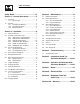
Table of Contents Residential Portable Generator System Safety Rules ..............................................1-3 Section 3 – Maintenance............................14 Section 1 – General Information ................4 3.1 Maintenance Schedule ................................................14 1.1 Unpacking ....................................................................4 1.1.1 Accessory Box..................................................4 3.2 1.2 Assembly ...............................
INTRODUCTION Thank you for purchasing this model of the GUARDIAN® product line by Generac Power Systems, Inc. This model is a compact, high performance, air-cooled, engine driven generator designed to supply electrical power to operate electrical loads when utility power is unavailable due to a power outage. READ THIS MANUAL THOROUGHLY If you do not understand any portion of this manual, contact your nearest GENERAC/GUARDIAN® Authorized Dealer for starting, operating and servicing procedures.
IMPORTANT SAFETY INSTRUCTIONS Residential Portable Generator System THESE INSTRUCTIONS – The manufacturer suggests that these rules for safe operation be copied and posted SAVE near the unit's installation site. Safety should be stressed to all operators and potential operators of this equipment. • Never start or stop the unit with electrical loads connected to receptacles AND with connected devices turned ON. Start the engine and let it stabilize before connecting electrical loads.
IMPORTANT SAFETY INSTRUCTIONS Residential Portable Generator System ELECTRICAL HAZARDS EXPLOSION HAZARDS • All generators covered by this manual produce dangerous electrical voltages and can cause fatal electrical shock. Utility power delivers extremely high and dangerous voltages as does the generator when it is in operation. Avoid contact with bare wires, terminals, connections, etc., while the unit is running.
Section 1 – General Information Residential Portable Generator System 1.1 UNPACKING 1.2 ASSEMBLY • Set the palleted carton on a rigid flat surface. • Remove staples along bottom of carton that fasten carton to pallet. Open carton from top. The generator requires some assembly prior to using it. If problems arise when assembling the generator, please call the Generator Helpline at 1-800-333-1322. • Remove all packaging material. 1.2.1 ASSEMBLING THE WHEEL KIT • Remove separate accessory box.
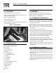
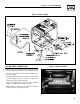
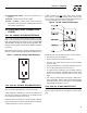
Section 1 - General Information Residential Portable Generator System Figure 2 - Handle Assembly 1.2.3 BATTERY CONNECTION • The battery shipped with the generator has been provided fully charged. Caution must be taken when connecting the battery. • Cut the tie wrap cable holding the RED and BLACK battery cables to the stator. Figure 3 - Battery Connections Negative Cable Positive Cable • Connect the RED battery cable to the battery Positive terminal (+).
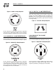
Section 2 – Operation Residential Portable Generator System OPERATION 7) 12 Volt DC, 10 Amp Receptacle – This receptacle allows the capability to recharge a 12 volt DC storage battery with provided battery charge cables. 120 Volt AC, 20 Amp, Duplex Receptacle – Supplies electrical power for the operation of 120 Volt AC, 20 Amp, single-phase, 60 Hz electrical lighting, appliance, tool and motor loads.
Section 2 – Operation Residential Portable Generator System 14) Start/Run/Stop Switch – Controls the operation of the generator. 15) Oil Fill – Use this point to add oil to engine. 16) Fuse - 10 Amp – Protects the DC control circuit from overload. If this fuse element has melted open the engine will not be able to crank and start. A GFCI receptacle does NOT protect against circuit overloads, short circuits, or shocks.
Section 2 – Operation Residential Portable Generator System Figure 9 - 120 VAC, 30 Amp Receptacle 2.2.5 12 VOLT DC, 10 AMP RECEPTACLE This receptacle allows you to recharge a 12 Volt automotive or utility style storage battery with the battery charge cables provided. This receptacle can not recharge 6 Volt batteries and can not be used to crank an engine having a discharged battery. See the section "Charging a Battery" (page 12) before attempting to recharge a battery.
Section 2 – Operation Residential Portable Generator System 2.3 HOW TO USE THE GENERATOR 2.3.2 CONNECTING ELECTRICAL LOADS If you have any problems operating your generator, please call the generator helpline at 1-800-333-1322. DO NOT connect 240 Volt loads to 120 Volt receptacles. DO NOT connect 3-phase loads to the generator. DO NOT connect 50 Hz loads to the generator. 2.3.1 GROUNDING THE GENERATOR • Let engine stabilize and warm up for a few minutes after starting.
Section 2 – Operation Residential Portable Generator System 2.5 WATTAGE REFERENCE GUIDE Device . . . . . . . . . . . . . . . . . . . . . . .Running Watts Hedge Trimmer . . . . . . . . . . . . . . . . . . . . . . . . . . . . .450 Impact Wrench . . . . . . . . . . . . . . . . . . . . . . . . . . . . . .500 Iron . . . . . . . . . . . . . . . . . . . . . . . . . . . . . . . . . . . . . .1200 *Jet Pump . . . . . . . . . . . . . . . . . . . . . . . . . . . . . . . . .800 Lawn Mower . . . . . . . . . . . . . . .
Section 2 – Operation Residential Portable Generator System Figure 15 - Fuel Shut-off Valve 2.6.2 ADDING GASOLINE ------------- WARNING ------------ WARNING: Never fill fuel tank indoors. Never fill fuel tank when engine is running or hot. DO NOT light a cigarette or smoke when filling the fuel tank. Caution: Do not overfill the fuel tank. Always leave room for fuel expansion. • Use regular UNLEADED gasoline with the generator engine. Do not use premium gasoline. Do not mix oil with gasoline.
Section 2 – Operation Residential Portable Generator System • Move engine CHOKE knob to “Full Choke” position. Figure 17 - Full Choke Position 2.9 AUTOMATIC IDLE CONTROL This feature is designed to greatly improve fuel economy. When this switch is turned “On,” the engine will only run at its normal fast governed engine speed when electrical load is connected. When the load is removed, the engine will run at a reduced speed of 2100 RPM.
Section 2 – Operation Residential Portable Generator System 2.12 CHARGING A BATTERY DANGER! Storage batteries give off explosive hydrogen gas while recharging. An explosive mixture will remain around the battery for a long time after it has been charged. The slightest spark can ignite the hydrogen and cause an explosion. Such an explosion can shatter the battery and cause blindness or other serious injury.
Section 3 — Maintenance Residential Portable Generator System 3.1 MAINTENANCE SCHEDULE Follow the calendar intervals. More frequent service is required when operating in adverse conditions noted below.
Section 3 — Maintenance Residential Portable Generator System 3.3 GENERAL RECOMMENDATIONS The warranty of the generator does not cover items that have been subjected to operator abuse or negligence. To receive full value from the warranty, the operator must maintain the generator as instructed in this manual. Some adjustments will need to be made periodically to properly maintain the generator. All adjustments in the Maintenance section (3) of this manual should be made at least once each season.
Section 3 — Maintenance Residential Portable Generator System 3.3.6 REPLACING THE SPARK PLUG To clean or replace foam pre-cleaner: Use Champion RC14YC spark plug or equivalent. The correct air gap is 0.76 mm (0.030 in.). Replace the plug once each year. This will help your engine start easier and run better. • Remove air cleaner cover, then foam pre-filter. 1. Stop the engine and pull the spark plug wire off of the spark plug. • Clean air cleaner cover before re-installing it. 2.
Section 3 — Maintenance Residential Portable Generator System Figure 21 - Spark Arrestor When valve clearance is correct, hold the pivot ball stud in place with the allen wrench and tighten the rocker arm jam nut. Tighten the jam nut to 174 in/lbs. torque. After tightening the jam nut, recheck valve clearance to make sure it did not change. Figure 22 - Valve Clearance Adjustment 3.6 ADJUSTING VALVE CLEARANCE After the first 50 hours of operation, you should adjust the valve clearance in the engine.
Section 3 — Maintenance Residential Portable Generator System 3.7 GENERAL 3.9 OTHER STORAGE TIPS: The generator should be started at least once every seven days and be allowed to run at least 30 minutes. If this cannot be done and you must store the unit for more than 30 days, use the following information as a guide to prepare it for storage. • Do not store gasoline from one season to another.
Section 4 — Troubleshooting Commercial-Industrial-Residential Portable Generator System 4.1 TROUBLESHOOTING SYMPTOM CAUSE SOLUTION Engine is running, but no AC output is available. 1. Circuit breaker is open. 2. Poor connection or defective cord set. 3. Connected device is bad. 4. Fault in generator. 1. Reset circuit breaker. 2. Check and repair. 3. Connect another device that is in good condition. 4. Contact Authorized Service Facility. 1. 2. 3. 4. 1. 2. 3. 4.
SECTION 5 - INSTALLATION GUIDE FOR GENERATOR READY KIT MAKES A HOME GENERATOR READY! GENERATOR READY KIT KIT INCLUDES: 1. 50 AMP PLUG ON 5FT. POWER CORD 3. Use with ULTRA SOURCE portable generator to supply power to load center. 2. THE EXTERNAL CONNECTION BOX Located outside the home where the generator will be operated. 3. 30’ FLEXIBLE CONDUIT Pre-wired from the automatic transfer switch with builtin 12 circuit load center for connection to the external connection box. 4.
1 Portable Generator Placement SECTION 5 - INSTALLATION GUIDE FOR GENERATOR READY KIT 3 2 1. PLAN THE LOCATION OF YOUR GENERATOR. 4. While adhering to all local electrical codes, route the 30 foot conduit along ceiling/floor joists and wall studs to the location where the conduit will pass through the wall to the exterior of the house. NOTE: Do not place the generator directly under a window. Select an area outside of your home where you can easily transport the portable generator to and from.
SECTION 5 - INSTALLATION GUIDE FOR GENERATOR READY KIT --- WARNING --- Threaded Lock Nut 6 The external connection box must be locked to ensure safety and to discourage tampering. The outer diameter of the threaded end is 15/16 inches. 9 Mounting Automatic Transfer Switch 1ft. 6. Remove the threaded lock nut from the conduit coupling. 7 Connect Wires Knockout 7. Remove the knock out in the lower right corner of the external connection box.
SECTION 5 - INSTALLATION GUIDE FOR GENERATOR READY KIT NOTE: Balance must be maintained when moving circuit locations from main electrical distribution panel to emergency load center. Circuit breaker positions alternate buss bars vertically. Circuits sharing a neutral wire should either be moved together to adjacent positions in emergency load center or not moved.
SECTION 6 - OPERATION OF GENERATOR WITH GENERATOR READY KIT GENERATOR READY KIT USING THE GENERATOR READY KIT WITH ULTRA SOURCE PORTABLE GENERATOR The GUARDIAN® Generator Ready Kit gives you the ability to hook up a GUARDIAN® ULTRA SOURCE portable generator to provide power safely and conveniently to vital items in your home including hard wired items. Included in the kit is a 5 foot electrical power cord and a 5 foot DC signal harness.
SECTION 6 - OPERATION OF GENERATOR WITH GENERATOR READY KIT SEMI-AUTOMATIC TRANSFER OPERATION USING GUARDIAN® PORTABLE GENERATOR TRANSFER TO GENERATOR POWER SOURCE WHEN UTILITY POWER FAILS 1. Connect ground strap to generator’s grounding lug and to grounding rod. 2. Set the generator’s 50 amp circuit breaker to its OFF (or open) position. 3. Insert the NEMA 14-50 plug (from the power cord that you have installed) into the mating receptacle on the generator control panel. 4. Start the generator. 5.
SECTION 6 - OPERATION OF GENERATOR WITH GENERATOR READY KIT GENERATOR READY KIT INTERCONNECTION DRAWING SEMI-AUTOMATIC TRANSFER SWITCH CONNECTED TO THE EXTERNAL CONNECTION BOX AND HOME’S MAIN ELECTRICAL DISTRIBUTION PANEL.
Section 7 - Notes Residential Portable Generator System 27
Section 8 — Electrical Data Commercial-Industrial-Residential Portable Generator System Wiring Diagram – Drawing No.
Section 8 — Electrical Data Commercial-Industrial-Residential Portable Generator System Schematic – Drawing No.
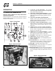
30 37 36 35 33 39 34 160 32 40 38 27 26 3 44 41 42 43 46 48 45 24 29 30 25 3 31 22 47 21 52 50 49 28 23 51 53 19 54 20 55 57 58 56 17 18 14 13 8 12 1 11 59 3, 30, 35, 65 60 2, 5, 17, 18, 34, 35, 40, 57, 139, 153 61 8, 11, 12, 13 62 4, 5, 6 63 7, 41, 42, 43, 44, 45, 46, 47, 49, 50, 51, 52, 53, 54, 57, 58 64 41, 42, 43, 44, 45, 46, 47, 49, 50, 51, 52, 53, 54, 56, 57, 58 65 25, 26, 27 10 15 6 2 7 9 4 160 5 16 Section 9 — Exploded Views and Parts Lists
Section 9 — Exploded Views and Parts Lists Commercial-Industrial-Residential Portable Generator System GT-990 & GT-760 Engine (Page 1) – Drawing No. 0E8589-J ITEM PART NO. QTY.
32 86 67 66 81 82 87 146 147 149 153 DETAIL "A" 74 73 69 68 80 85 143 144 37 150 75 71 72 145 70 83 143 140 151 79 142 84 78 141 100 76 139 107 101 93 160 92 90 91 77 92 93 136 135 108 138 109 106 152 108 110 137 89 103 104 94 97 98 99 102 105 95 96 160 147 108 132 131 133 129 130 134 155 111 128 154 157 158 126 108 127 157 159 114 155 122 123 125 115, 161 114 120 124 116 119 118 DETAIL "A" 113 112 113 121 117 Section
Section 9 — Exploded Views and Parts Lists Commercial-Industrial-Residential Portable Generator System GT-990 & GT-760 Engine (Page 2) – Drawing No. 0E8589-J ITEM PART # 66 67 68 69 70 71 72 73 74 75 76 77 78 79 80 81 82 83 84 85 86 87 89 90 QTY.
Section 9 — Exploded Views and Parts Lists Commercial-Industrial-Residential Portable Generator System Generator – Drawing No.
Section 9 — Exploded Views and Parts Lists Commercial-Industrial-Residential Portable Generator System Generator – Drawing No. 0D4488-D ITEM PART NO. QTY. DESCRIPTION ITEM PART NO. QTY.
36 2 1 5 60 43 42 44 41 9 8 56 21 3 11 8 14 10 9 63 20 6 64 17 18 23 12 40 59 39 13 15 42 46 27 41 26 8 59 42 28 59 42 18 41 9 8 17 55 41 16 19 41 22 45 25 17 42 18 50 53 33 7 34 35 37 36 4 31 32 30 49 29 54 51 47,48 17 52 4 18 24 58 38 61 62 57 Section 9 — Exploded Views and Parts Lists Commercial-Industrial-Residential Portable Generator System Control Panel – Drawing No.
Section 9 — Exploded Views and Parts Lists Commercial-Industrial-Residential Portable Generator System Control Panel – Drawing No. 0E0227-C ITEM PART NO. QTY. DESCRIPTION ITEM PART NO. QTY.
Section 9 — Exploded Views and Parts Lists Commercial-Industrial-Residential Portable Generator System Frame, Handle & Wheel Kit – Drawing No.
Section 9 — Exploded Views and Parts Lists Commercial-Industrial-Residential Portable Generator System Frame, Handle & Wheel Kit – Drawing No. 0E0695-A ITEM PART NO. 1 2 3 4 5 6 7 8 9 10 11 12 13 14 15 16 17 18 19 20 21 22 23 24 25 26 27 28 QTY.
Section 10 – Warranty Commercial-Industrial-Residential Portable Generator System CALIFORNIA EMISSION CONTROL WARRANTY STATEMENT YOUR WARRANTY RIGHTS AND OBLIGATIONS The California Air Resources Board (CARB) and Generac Power Systems, Inc. (Generac) are pleased to explain the Emission Control System warranty on your new engine. In California, new off-road Large Spark-Ignition (LSI) engines must be designed, built and equipped to meet the state's stringent anti-smog standards.
Section 10 – Warranty Commercial-Industrial-Residential Portable Generator System EMISSION CONTROL SYSTEM WARRANTY Emission Control System Warranty (ECS warranty) for 2001 and later model year LSI engines: (a) Applicability: This warranty shall apply to 1995 and later model year engines. The ECS Warranty period shall begin on the date the new engine or equipment is purchased by/delivered to its original, end-use purchaser/owner and shall continue for 24 consecutive months thereafter.
Section 8 – Warranty Commercial-Industrial-Residential Portable Generator System GENERAC POWER SYSTEMS "TWO YEAR" LIMITED WARRANTY FOR GUARDIAN® "ULTRA SOURCE 15,000 WATT GENERATOR WITH GENERATOR READY KIT" For a period of two years from the date of original sale, Generac Power Systems, Inc. (Generac) warrants that its Guardian generator and accompanying transfer switch will be free from defects in material and workmanship for the items and period set forth below.