Owner’s Manual and Installation Instructions Air-cooled Recreational Vehicle Generators This manual should remain with the unit.
Introduction Thank you for purchasing this model of the QUIETPACT product line. This model is designed and manufactured to supply electrical power for recreational vehicles. Read This Manual Thoroughly If any portion of this manual is not understood, contact an Authorized Service Dealer for starting, operating and servicing procedures.
Table of Contents Recreational Vehicle Generator Part I – Owner’s Manual Part II – Installation Instructions Introduction.........................................Inside Front Cover Safety Rules...................................................................... 16 Read This Manual Thoroughly........................................ IFC Contents......................................................................... IFC Operation and Maintenance............................................
Safety Rules Recreational Vehicle Generator S ave These Instructions – The manufacturer suggests that these rules for safe operation be copied and posted in potential hazard areas of the recreational vehicle. Safety should be stressed to all operators and potential operators of this equipment. WARNING! This product contains or emits chemicals known to the state of California to cause cancer, birth defects or other reproductive harm.
Safety Rules Recreational Vehicle Generator • When working on this equipment, remain alert at all times. Never work on the equipment when physically or mentally fatigued. • Inspect the generator regularly, and contact the nearest Authorized Service Dealer immediately for parts needing repair or replacement. • Before performing any maintenance on the generator, disconnect its battery cables to prevent accidental start up. Disconnect the cable from the battery post indicated by a NEGATIVE, NEG or (–) first.
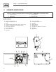
Section 1 – General Information Recreational Vehicle Generator 1.1 Generator Identification Please record the following information from the generator DATA DECAL or information decal. 1. Model Number______________________ 2. Serial Number___________________ 3. kW Rating_ _________________________ 4. Rated Voltage___________________ Model: 004701-0 1. Generator Air Intake 2. Engine Start/Stop Switch 3. Fuse 4. Optional Remote Panel Receptacle (Side View) 5. Generator AC Output Leads (Side View) 6.
Section 1 – General Information Recreational Vehicle Generator 1.2 GENERATOR APPLICABILITY These generators have been designed and manufactured for supplying electrical power for recreational vehicles. Do not modify the generator or use it for any application other than for what it was designed. If there are any questions pertaining to its application, write or call the factory. Do not use the unit until advised by a competent authority.
Section 1 – General Information Recreational Vehicle Generator 1.5.3 engine oil requirements Use only high quality detergent oil rated with American Petroleum Institute (API) Service Classification SF, SG or SH. The recommended oil weights include the following: • During summer months: SAE 30. An acceptable substitute is SAE 10W-30. • During winter months: SAE 5W-30. DO NOT USE SAE 10-W40. Crankcase and oil filter capacity is approximately 800 mL or .84 U.S. quarts. Do NOT use special additives.
Section 2 – Operation Recreational Vehicle Generator 2.2 optional remote start/stop panel A remote mounted Start/Stop Panel is available that permits starting and stopping the generator engine conveniently from inside the vehicle. Contact an Authorized Service Dealer to order, a remote panel that includes a Start/Stop switch, a generator run lamp, a fuel prime switch, and an hourmeter. The hourmeter provides a continuous indication of engine/generator operating time.
Section 2 – Operation Recreational Vehicle Generator NOTE: If starting from the generator control panel, turn OFF loads by setting the generator’s main circuit breaker to the OFF (or open) position. If starting from a remote panel, turn OFF loads using the means provided in the vehicle (such as a main circuit breaker). Electrical load circuits will be turned ON after the generator has started, stabilized and warmed up. 2.
Section 2 – Operation Recreational Vehicle Generator Figure 2.2 – Low Oil Pressure and High Temperature Switches Figure 2.4 – Solid State Voltage Regulator High Temperature Switch Low Oil Pressure Switch The voltage regulator also incorporates a “voltage surge protection circuit.” This circuit prevents troublesome surges in the generator AC output voltage. Voltage surge is a common cause of damage to electronic equipment. 2.8.
Section 3 – Maintenance Recreational Vehicle Generator 2.9.3 attention required after submersion If the recreational vehicle generator has been submerged in water, it must not be started and operated. Following any submersion in water, have an Authorized Service Dealer thoroughly clean and dry the generator. 2.9.4 OPERATion in high grass orbrush Never operate the generator while the vehicle is parked over high grass, weeds, brush, leaves or any other combustible substance.
Section 3 – Maintenance Recreational Vehicle Generator • Change the engine oil filter after the first 25 hours of operation, and every 100 operating hours thereafter. To change the oil and/or oil filter, proceed as follows (see Figure 3.1): 1. Run the engine until it is thoroughly warmed up (at least five minutes) then shut OFF the engine. 2. Immediately after the engine shuts OFF, pull the oil drain cover free of the base.
Section 3 – Maintenance Recreational Vehicle Generator Figure 3.3 – Cleaning Air Intake 3.6 clean spark arrestor The engine exhaust muffler has a spark arrestor screen. Inspect and clean the screen every 50 hours of operation or once each year, whichever comes first (Figure 3.5). NOTE: If using the generator on any forest-covered, brush-covered or grass-covered unimproved land, it must equipped with a spark arrestor. The spark arrestor must be maintained in good condition by the owner/operator.
Section 3 – Maintenance Recreational Vehicle Generator Do NOT use a forceful spray of water to clean the generator. Water will enter the generator interior and cause problems, and may also contaminate the generator fuel system. 3.8 Battery Maintenance All lead-acid batteries will discharge when not in use. The generator battery should be inspected as follows: 3.8.1 Weekly • Inspect the battery posts and cables for tightness and corrosion. Tighten and clean as necessary.
Section 3 – Maintenance Recreational Vehicle Generator 3. While the engine is still warm from running, drain the oil completely. Refill the crankcase with SAE 10W-30 oil having API classification “For Service SF.” 4. Attach a tag to the engine indicating the viscosity and classification of the oil in the crankcase. 5. Remove the spark plug and pour two or three tablespoons of clean, fresh engine oil into the spark plug threaded openings. Reinstall and tighten the spark plug. 6.
Part II – Installation Instructions danger Only qualified electricians or contractors
Safety Rules Recreational Vehicle Generator DANGER: For fire safety, installation of a generator into a recreational vehicle must comply strictly with article 551, NFPA 70; ANSI C1-1975; AND, ANSI A119.2-1975/NFPA 501C “Standard for Recreational Vehicles” (Part 3, “Installation of Electrical Systems”). In addition, installation must comply with the manufacturer’s instructions and recommendations.
Safety Rules Recreational Vehicle Generator Electrical Hazards Fire Hazards • The generator covered by this manual produces dangerous electrical voltages and can cause fatal electrical shock. Avoid contact with bare wires, terminals, connections, etc., while the unit is running. Ensure all appropriate covers, guards and barriers are in place before operating the generator. If work must be done around an operating unit, stand on an insulated, dry surface to reduce shock hazard.
Section 1 – General Information Recreational Vehicle Generator 1.1 PURPOSE AND SCOPE OF the MANUAL These Installation Instructions have been prepared especially for the purpose of familiarizing installers and owners of the applicable equipment with the product's installation requirements. Give serious consideration to all information and instructions in the manual, both for safety and for continued reliable operation of the equipment.
55.5 [2 3/16"] 37 6. 5 [14 13/16"] 429.5 [16 15/16"] 476.4 [18 3/4"] 342.2 [13 1/2"] 29 [1 1/8"] 48.1 [1 7/8"] TAIL PIPE EXIT 416 [16 3/8"] HOT AIR EXHAUST TYP. 6.7 [1/4"] 50.8 [2"] 222.7 [8 3/4"] 210 [8 1/4"] 369.7 [14 9/16"] 34 3.4 [13 1/2"] 300.7 [11 13/16"] 101 [4"] 82.5 [3 1/4"] 423.2 [16 11/16"] 736.4 [29"] OIL DRAIN 36.5 [1 7/16 7/16"] 83.5 [3 5/16"] 176.6 [6 15/16"] 170 [6 11/16"] FRONT DOOR ACCESS FOR ALL REQUIRED MAINTENANCE 778.9 [30 11/16"] REF. 688.
Section 2 – Installation Recreational Vehicle Generator 2.1 Location and Support 2.1.1 GENERATOR LOCATION The most desirable location for the generator set is between the vehicle's main frame members. However, this is seldom possible. Most units must be installed on the side of the vehicle and are difficult to reinforce. Many recreational vehicles have been factory equipped with an area for the generator set. Some vehicles may even have a generator compartment provided by the vehicle manufacturer.
Section 2 – Installation Recreational Vehicle Generator 2.2 Generator Compartments Figure 2.4 – Typical Compartment Construction Whether the generator set is being installed inside a compartment specifically manufactured to house a generator or inside a compartment that the installer constructs, the compartment must meet certain specifications as outlined in the following sections: 2.2.1 COMPARTMENT SIZE Plan the compartment size carefully.
Section 2 – Installation Recreational Vehicle Generator Figure 2.5 – Types of Lock Seams 2.2.4 ACOUSTICS For additional noise abatement, the installer may wish to consider the following: • Using special sound insulating materials. • Construction of a special noise abatement compartment. NOTE: Any method used to reduce noise must not adversely affect the flow of cooling and ventilating air into or out of the compartment.
Section 2 – Installation Recreational Vehicle Generator Figure 2.7 – Compartment Floor Cutout (Drawing 0F4610) VIEW FROM TOP 423.2 [16 11/16"] TYP. 6.7 [1/4"] 82.5 [3 1/4"] 717.7 [28 1/4"] 343.4 [13 1/2"] CONNECTIONS IN BACK OF GENERATOR 50.8 [2"] 476.4 [18 3/4"] 60 [2 3/8"] 376.5 [14 13/16"] 170 [6 11/16"] 210 [8 1/4"] HOT AIR EXHAUST 429.5 [16 15/16"] NOTE: ALL AIR INTAKES AND EXHAUST OUTLETS MUST BE KEPT CLEAR OF ANY OBSTRUCTIONS. ALL OPEN AREA IS REQUIRED FOR COOLING.
Section 2 – Installation Recreational Vehicle Generator Figure 2.8 – Airflow Through Engine/Generator danger Use only approved components in the fuel sup ply system. All components must be properly installed in accordance with applicable codes. Improper installation or use of unauthorized components may result in fire or an explosion. Follow approved methods to test the system for leaks. No leakage is permitted. Do not allow fuel vapors to enter the vehicle interior. Figure 2.
Section 2 – Installation Recreational Vehicle Generator • Use a length of approved flexible fuel hose between the gaseous fuel solenoid valve and rigid gas piping. The flexible line should be at least 6 inches longer than necessary. Figure 2.10 – LP Gas Carburetion Diagram 2.4.3 vapor withdrawal LP gas is stored in pressure tanks as a liquid. The gas systems used with these generators were designed only for vapor withdrawal type systems.
Section 2 – Installation Recreational Vehicle Generator 2.4.8 leakage tests Do not place the generator into service until the gas system has been properly tested for leaks. To test the system, a separate source of 12 volts DC is needed to open the gaseous fuel solenoid valve. The leak test must comply fully with NFPA, Paragraph 318.
Section 2 – Installation Recreational Vehicle Generator Figure 2.12 — Spark Arrestor Installation 2.6 Electrical Connections Be sure to read Section 1.6. The following general rules apply to electrical connections in a recreational vehicle: 27.4 [1.08"] I.D. 40 [1.58"] 5.5 [7/32"] DRILL BOTTOM SIDE ONLY 2.5.
LP FUEL INLET 414.5 [16 5/16"] Section 2 – Installation 360.5 [14 3/16"] Recreational Vehicle Generator 211.3 [8 5/16"] 6"] ] 71.2 [2 13/16"] POS. BAT. CONNECTION 34.3 [1 3/8"] • Conductors must be rated 221° F (105° C) or must NEG. BAT. be of a larger conductor size. 69.6 CONNECTION 39.6 [1 9/16"] [2 3/4"] 2.6.3 GENERATOR AC CONNECTIONS Generator AC output leads (BLACK) “hot” and (WHITE) grounded neutral come out of the generator as shown in Figure 2.13.
Section 2 – Installation Recreational Vehicle Generator Figure 2.14 – Transfer Switch Isolation Method Figure 2.15 – Installation With Isolation Receptacle These generators are rated at about 100 DC amperes of cranking current. CABLE LENGTH in Feet (Meters) CABLE SIZE Select battery cables based on (a) cable length and (b) prevailing ambient temperatures. Generally, the longer the cable and the colder the weather, the larger the cable size must be, as shown in the following chart.
Section 2 – Installation Recreational Vehicle Generator 2.7.3 BATTERY CABLE CONNECTIONS Figure 2.17 – Remote Panel Plug-in Receptacle 1. Connect the battery cable from the battery post or to NOTE: ALL AIR INTAKES AND EXHAUST OUTLETS MUST BE terminal indicated by a POSITIVE, POS or (+) KEPT CLEAR OF ANY OBSTRUCTIONS. ALL OPEN AREA the lug on the starter contactor (Figure 2.16). IS REQUIRED FOR COOLING. NOTE: Check to be sure the battery cable boot for the starter cable has been installed.
Section 3 – Post-installation Start-up Adjustments Recreational Vehicle Generator 3.1 Post Installation Tests The air-cooled generator set was factory tested and adjusted. It should not be necessary to adjust the unit any further except under special circumstances. Do not make any unnecessary adjustments. Factory settings are correct for most applica- tions. When making adjustments, however, be careful to avoid overspeeding the engine. 3.
Section 3 – Post-Installation Start-up Adjustments Recreational Vehicle Generator 3.5 Installation Checklist Electrical Connections Location and support ❑ Connections comply with local code requirements and all National Electrical Codes. ❑ Generator is properly located. ❑ Junction box is properly installed. ❑ Generator is properly supported. ❑ Wiring meets all standards. ❑ Generator is properly restrained. ❑ All connections are correct.
Appendix 1 – Troubleshooting Recreational Vehicle Generator Troubleshooting Guide Problem Cause Correction The engine will not crank. 1. 2. 3. 4. 5. 6. Fuse blown 1. Loose, corroded or defective 2. battery cables Defective engine Start/Stop 3. switch Defective starter contactor 4. Defective starter motor 5. Low or defective battery 6. Replace fuse. Tighten, clean or replace as necessary. Replace Start/Stop switch. The engine cranks but will not start. Out of fuel 1. Defective fuel solenoid 2.
Appendix 2 — Electrical Data Recreational Vehicle Generator Electrical Schematic and Wiring Diagram – Drawing No.
Appendix 2 — Electrical Data Recreationl Vehicle Generator Electrical Schematic and Wiring Diagram – Drawing No.
36 41 5 16 38 21 45 4 15 2 46 37 42 52 3 17 19 34 33 52 50 9 30 32 31 52 21 40 51 52 21 43 21 36 28 41 21 21 39 54 1 21 53 18 22 23 11 10 24 20 6 42 8 47 7 24 13 23 14 22 25 49 21 12 26 44 Appendix 3 — Exploded Views and Parts Lists Recreational Vehicle Generator Enclosure – Drawing No.
Appendix 3 — Exploded Views and Parts Lists Recreational Vehicle Generator Enclosure – Drawing No. 0F4589 ITEM 1 2 3 4 5 6 7 8 9 10 11 12 13 14 15 16 17 18 19 20 21 22 23 24 25 26 27 28 30 31 32 33 34 35 36 37 38 39 40 41 42 43 44 45 46 47 48 49 50 51 52 53 54 PART NO.
Appendix 3 — Exploded Views and Parts Lists 18 18 37 18 21 28 38 23 21 2 18 27 26 10 25 2 18 1 4 3 5 2 7 24 8 24 9 22 2 35 11 12 39 2 15 18 2 23 36 13 2 2 8 2 14 17 18 43 16 2 0 1 21 29 32 30 42 34 31 29 33 Recreational Vehicle Generator Generator – Drawing No.
Appendix 3 — Exploded Views and Parts Lists Recreational Vehicle Generator Generator – Drawing No. 0F4590 ITEM 1 2 3 4 5 6 7 8 9 10 11 12 13 14 15 16 17 18 19 20 21 22 23 24 25 26 27 28 29 30 31 32 33 34 35 36 37 38 39 41 42 43 PART NO.
Appendix 3 — Exploded Views and Parts Lists Recreational Vehicle Generator Control Panel – Drawing No.
Appendix 3 — Exploded Views and Parts Lists Recreational Vehicle Generator Control Panel – Drawing No. 0F4591 ITEM 1 2 3 4 5 6 7 8 9 10 11 12 13 14 15 16 17 18 19 20 21 22 23 24 25 26 27 28 29 30 31 32 33 34 35 36 37 PART NO. 0830490 075210A 092234 065795 023484F 023484R 075234 057159 054502 087798 092113 032300 0A9611 090145 0E2314 0A1658 075235 047411 049226 051716 075476 022264 051715 0A2053 022473 022097 049813 055440 049815 038750 051714 0D8794 025105 028739 0D8308 0F5025 023484S 043182 031879 QTY.
Appendix 3 — Exploded Views and Parts Lists 51 50 48 6 49 31 37 52 30 28 53 32 29 23 24 25 22 21 34 44 38 9 9 41 42 43 46 47 9 18 45 20 40 14 19 13 26 27 8 9 10 11 12 35 36 7 15 16 16 15 33 3 9 9 1 2 Recreational Vehicle Generator GN-220 H/SH Engine – Drawing No.
Appendix 3 — Exploded Views and Parts Lists Recreational Vehicle Generator GN-220 H/SH Engine – Drawing No. 0F5791 Part 1 ITEM 1 2 3 4 5 6 7 8 9 10 11 12 13 14 15 16 17 18 19 20 21 22 23 24 25 26 27 28 29 30 31 32 33 34 35 36 37 38 39 40 41 42 43 44 45 46 47 48 49 50 51 52 53 PART NO.
Appendix 3 — Exploded Views and Parts Lists 13 47 11 12 7 21 18 39 40 1 36 46 31 26 25 48 23 22 24 44 43 42 50 28 13 44 45 30 17 4 32 20 34 37 5 49 38 41 35 16 15 19 1 29 52 8 10 7 51 2 3 6 9 10 Recreational Vehicle Generator GN-220 H/SH Engine – Drawing No.
Appendix 3 — Exploded Views and Parts Lists Recreational Vehicle Generator GN-220 H/SH Engine – Drawing No. 0F5791 Part 2 ITEM N/A 1 2 3 4 5 6 7 8 9 10 11 12 13 14 15 16 17 18 19 20 21 22 23 24 25 26 27 28 29 30 31 32 33 34 35 36 37 38 39 40 41 42 43 44 45 46 47 48 49 50 51 52 PART NO.
Appendix 3 — Exploded Views and Parts Lists Recreational Vehicle Generator Regulator – Drawing No.
Appendix 3 — Exploded Views and Parts Lists Recreational Vehicle Generator Regulator – Drawing No. 0F5819 ITEM 1 2 3 4 5 6 7 8 9 10 11 12 13 14 15 16 17 18 19 20 21 22 23 24 25 26 PART NO. 0D5694 0F4795 0F5022 0C6070 0C4680 0C4647 0C4643 0D3973 0D7020A 026073 0D3308 070728 0C5764 0C4643A 0C5764 0C5968 0C5759 0C5761 0C6069 0C6731 0C6067 0C4706 0C6068 0C5762 045764 0C5760K QTY. 1 4 1 1 1 1 1 1 1 2 2 2 1 1 1 1 1 1 1 1 1 1 1 1 8 1 DESCRIPTION CASTING, TWIN REGULATOR HOUSING SCREW PPHM SEMS M4-0.
Appendix 4 – Warranty Recreational Vehicle Generator CALIFORNIA AND FEDERAL EMISSION CONTROL WARRANTY STATEMENT YOUR WARRANTY RIGHTS AND OBLIGATIONS The California Air Resources Board (CARB) and the United States Environmental Protection Agency (EPA), together with Generac Power Systems, Inc. (Generac), are pleased to explain the Emission Control System Warranty on your new engine.
Appendix 4 – Warranty Recreational Vehicle Generator EMISSION CONTROL SYSTEM WARRANTY Emission Control System Warranty (ECS Warranty) for 1997 and later model year engines: (a) Applicability: This warranty shall apply to 1997 and later model year engines. The ECS Warranty Period shall begin on the date the new engine or equipment is purchased by/delivered to its original, end-use purchaser/owner and shall continue for 24 consecutive months thereafter.
Appendix 4 – Warranty Recreational Vehicle Generator GENERAC POWER SYSTEMS’ Three-YEAR LIMITED WARRANTY FOR Guardian Recreational Vehicle Generators NOTE: All units must be installed by Generac Power Systems Authorized Service Facilities. For a period of 3 (three) years of operation from the date of original sale, Generac Power Systems, Inc.