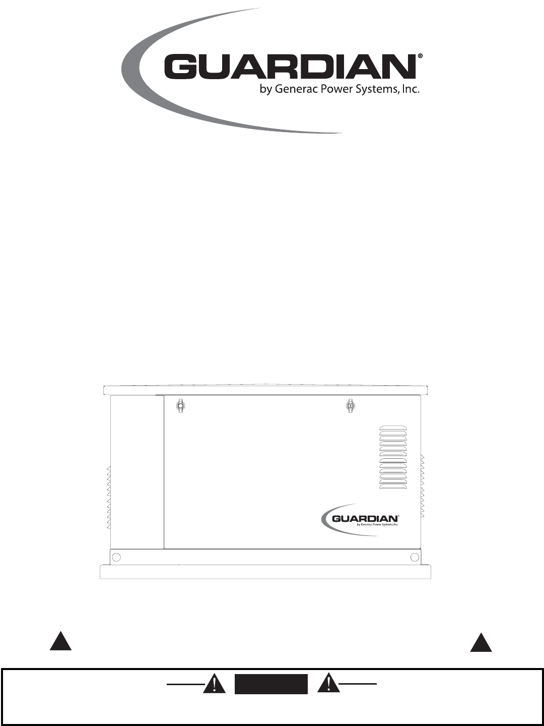
Installation and Owner’s Manual Air-cooled Automatic Standby Generators Models: 04758-2 (6 kW NG, 7 kW LP) 04759-2 (12 kW NG, 12 kW LP) 04760-2 (13 kW NG, 15 kW LP) GENERAC R POWER SYSTEMS, INC. R *This manual should remain with the unit.* ! Not intended for use as Primary Power in place of utility or in life-support applications. DANGER DEADLY EXHAUST FUMES.
INTRODUCTION Thank you for purchasing this Guardian model by Generac Power Systems Inc.. This model is a compact, high performance, air-cooled, engine-driven generator designed to automatically supply electrical power to operate critical loads during a utility power failure. This unit is factory installed in an all-weather, metal enclosure that is intended exclusively for outdoor installation. This generator will operate using either vapor withdrawn liquid propane (LP) or natural gas (NG).
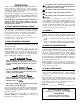
Table of Contents Guardian Air-cooled 7 kW, 12 kW and 15 kW Generators Introduction ........................Inside Front Cover 3.2.2 “Off” Position ....................................14 Read This Manual Thoroughly ........................IFC Contents ..........................................................IFC Operation and Maintenance ............................IFC How to Obtain Service ....................................IFC Authorized Dealer Locator Number ....................IFC 3.2.
IMPORTANT SAFETY INSTRUCTIONS Guardian Air-cooled 7 kW, 12 kW and 15 kW Generators SAVE THESE INSTRUCTIONS – The manufacturer suggests that these rules for safe operation be copied and posted near the unit’s installation site. Safety should be stressed to all operators and potential operators of this equipment. ! ! WARNING: ! GENERAL HAZARDS ! ! The engine exhaust from this product contains chemicals known to the state of California to cause cancer, birth defects or other reproductive harm.
IMPORTANT SAFETY INSTRUCTIONS Guardian Air-cooled 7 kW, 12 kW and 15 kW Generators ELECTRICAL HAZARDS • All generators covered by this manual produce dangerous electrical voltages and can cause fatal electrical shock. Utility power delivers extremely high and dangerous voltages to the transfer switch as does the standby generator when it is in operation. Avoid contact with bare wires, terminals, connections, etc., while the unit is running.
Section 1 — General Information Guardian Air-cooled 7 kW, 12 kW and 15 kW Generators DANGER ! 1.1 Only qualified electricians or contractors should attempt such installations, which must comply strictly with applicable codes, standards and regulations. UNPACKING/INSPECTION After unpacking, carefully inspect the contents for damage. • This standby generator set has been factory supplied with a weather protective enclosure that is intended for outdoor installation only. 1.
Section 1 — General Information Guardian Air-cooled 7 kW, 12 kW and 15 kW Generators 1.4 THE GENERATOR Figure 1.1 – 7 kW, Single Cylinder GH-410 Engine Oil Dipstick Control Panel Data Decal GFCI Outlet Exhaust Enclosure Fuel Regulator Fuel Inlet Battery Compartment Oil Filter Figure 1.
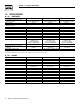
Section 1 — General Information Guardian Air-cooled 7 kW, 12 kW and 15 kW Generators 1.5 SPECIFICATIONS 1.5.1 GENERATOR Rated Max. Continuous Power Capacity (Watts*) Rated Voltage Rated Max.
Section 1 — General Information Guardian Air-cooled 7 kW, 12 kW and 15 kW Generators 1.6 FUEL REQUIREMENTS AND RECOMMENDATIONS 1.8 With LP gas, use only the vapor withdrawal system. This type of system uses the vapors formed above the liquid fuel in the storage tank. The engine has been fitted with a fuel carburetion system that meets the specifications of the 1997 California Air Resources Board for tamper-proof dual fuel systems.
Section 1 — General Information Guardian Air-cooled 7 kW, 12 kW and 15 kW Generators NOTE: The natural gas adjustment screw is preset during installation and should not need any further adjustment. ◆ 1.8.2 12KW AND 15KW, 990CC ENGINES 13. To adjust the system to run on LP fuel, turn BOTH adjuster screws 1/2 TURN CLOCKWISE. The system should now be set for maximum power and best perfomance. DO NOT, UNDER ANY CIRCUMSTANCES, REMOVE THE SET PINS FROM THE REGULATOR HOUSING. THIS WILL VOID THE WARRANTY.
Section 1 — General Information Guardian Air-cooled 7 kW, 12 kW and 15 kW Generators ◆ 1.9.2 TRANSFER SWITCH Figure 1.5 – Battery Cable Connections 1.9.2.1 7 kW, 12 kW and 15 kW Units Transfer switches for use with these generators are sold separately and can be purchased from Generac Authorized Dealers. • Install the transfer switch on a firm, sturdy supporting structure. • To prevent switch distortion, level the switch if necessary.
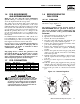
Section 2 — Post Installation Start-up and Adjustments Guardian Air-cooled 7 kW, 12 kW and 15 kW Generators • • • • Remove watches, rings or other metal objects; Use tools with insulated handles; Wear rubber gloves and boots; Do not lay tools or metal parts on top of the battery; and • Disconnect charging source prior to connecting or disconnecting battery terminals. ! Do not open or mutilate the battery. Released electrolyte has been known to be harmful to the skin and eyes, and to be toxic.
Section 2 — Post Installation Start-up and Adjustments Guardian Air-cooled 7 kW, 12 kW and 15 kW Generators 3. Check utility power source voltage across terminals N1 and the transfer switch neutral lug; then across terminal N2 and neutral. Nominal line-toneutral voltage should be 120 volts AC. 4. When certain that utility supply voltage is compatible with transfer switch and load circuit ratings, turn OFF the utility power supply to the transfer switch. 5.
Section 2 — Post Installation Start-up and Adjustments Guardian Air-cooled 7 kW, 12 kW and 15 kW Generators 4. Manually set the transfer switch to the UTILITY position, i.e., load terminals connected to the utility power source side. 5. Turn ON the utility power supply to the transfer switch, using the means provided (such as a utility main line circuit breaker). 6. Set the AUTO/OFF/MANUAL switch to AUTO. Then set the generator’s main circuit breaker to its ON (or closed) position.
Section 2 — Post Installation Start-up and Adjustments Guardian Air-cooled 7 kW, 12 kW and 15 kW Generators If this procedure or equipment are not available, locate the nearest Generac Guardian Dealer and they can perform the adjustments. NOTE: A service fee may be charged for this adjustment. 2.7 ◆ 2.7.2 12 KW AND 15 KW UNITS 1. Loosen governor clamp bolt (See Figure 2.4). Figure 2.
Section 3 — Operation Guardian Air-cooled 7 kW, 12 kW and 15 kW Generators ◆ 2.7.3 ADDITIONAL CORROSION PROTECTION Periodically spray all engine linkage parts and brackets with corrosion inhibiting spray such as WD-40 or a comparable product. 2.8 VOLTAGE REGULATOR ADJUSTMENT With the frequency between 62-63.5 Hertz, slowly turn the slotted potentiometer (Figure 2.6) until line voltage reads 244-252 volts. NOTE: Remove the access panel on top of the control panel to adjust the voltage regulator.
Section 3 — Operation Guardian Air-cooled 7 kW, 12 kW and 15 kW Generators 3.3 AUTOMATIC TRANSFER OPERATION To select automatic operation, do the following: 1. Make sure the transfer switch main contacts are set to their “Utility” position, i.e., loads connected to the utility power source (Figure 3.2). 2. Be sure that normal utility power source voltage is available to transfer switch terminal lugs N1 and N2. 3. Set the generator’s AUTO/OFF/MANUAL switch to AUTO. 4.
Section 3 — Operation Guardian Air-cooled 7 kW, 12 kW and 15 kW Generators Figure 3.2 – Manual Transfer Switch Operation 3.6 SETTING THE EXERCISE TIMER The generator is equipped with an exercise timer. Once it is set, the generator will start and exercise once every seven days, on the day of the week and at the time of day the following sequence is completed. During this exercise period, the unit runs for approximately 12 minutes and then shuts down.
Section 4 — Maintenance Guardian Air-cooled 7 kW, 12 kW and 15 kW Generators Figure 3.3 – Low Oil Pressure and High Temperature Switches Low Oil Switch High Temp Switch The generator panel’s 5 amp fuse protects the battery charge circuit against overload. If the fuse element has melted open, battery charging capability will not be possible. Replace the fuse using only an identical 5 amp replacement. To remove fuse, push cap down and rotate counterclockwise. Figure 4.
Section 4 — Maintenance Guardian Air-cooled 7 kW, 12 kW and 15 kW Generators 4. Install the dipstick. 5. Reset the AUTO/OFF/MANUAL switch to its original position. Figure 4.4 – Oil Drain Hose and Filter Figure 4.3 — Oil Dipstick and Fill, 12 kW and 15 kW Loos en Oil Dipstick Oil Fill Oil Drain Hose Oil Filter 4.4 CHANGING THE OIL FILTER Change the engine oil filter as follows: 4.3 CHANGING THE ENGINE OIL 4.3.
Section 4 — Maintenance Guardian Air-cooled 7 kW, 12 kW and 15 kW Generators Figure 4.6 — 7 kW, Engine Air Cleaner Location Air Cleaner Figure 4.8 – Setting the Spark Plug Gap Fuel Regulator SET PLUG GAP AT 0.76 mm (0.030 inch) 7kW (0.508 mm (0.020 inch) 12/15kW 4.7 3/4" Hole Figure 4.7 — 12 kW and 15 kW Engine Air Cleaner Screw Cover BATTERY MAINTENANCE The battery should be inspected per the “Service Schedule,” Section 4.13. The following procedure should be followed for inspection: 1.
Section 4 — Maintenance Guardian Air-cooled 7 kW, 12 kW and 15 kW Generators • Where electrolyte contacts the eyes, immediately flush thoroughly with water and seek medical attention; and • Spilled electrolyte is to be washed down with an acid neutralizing agent. A common practice is to use a solution of 1 pound (500 grams) bicarbonate of soda to 1 gallon (4 liters) or water. The bicarbonate of soda solution is to be added until the evidence of reaction (foaming) has ceased.
Section 4 — Maintenance Guardian Air-cooled 7 kW, 12 kW and 15 kW Generators Figure 4.9 – Cooling Vent Locations 6. Attach a tag to the engine indicating the viscosity and classification of the oil in the crankcase. 7. Remove the spark plug(s) and spray fogging agent into the spark plug(s) threaded openings. Reinstall and tighten the spark plug(s). 8. Remove the battery and store it in a cool, dry room on a wooden board. Never store the battery on any concrete or earthen floor. 9.
Section 4 — Maintenance Guardian Air-cooled 7 kW, 12 kW and 15 kW Generators 4.13 SERVICE SCHEDULE ATTENTION: It is recommended that all service work be performed by the nearest Generac Authorized Dealer. SYSTEM/COMPONENT X = Action R = Replace as Necessary * = Notify Dealer if Repair is Needed.
Section 5 — Troubleshooting Guardian Air-cooled 7 kW, 12 kW and 15 kW Generators 5.1 TROUBLESHOOTING GUIDE PROBLEM CAUSE The engine will not crank. 1. Fuse blown 1. Replace 15A fuse on generator control panel. 2. Loose, corroded or defective 2. Tighten, clean or replace battery cables as necessary. 3. Defective starter contactor (7 kW) 3. * 4. Defective starter motor 4. * 5. Dead Battery 5. Charge or replace battery. The engine cranks but will not start. 1. Out of fuel 2.
Section 6 — Electrical Data Guardian Air-cooled 7 kW, 12 kW and 15 kW Generators Wiring Diagram – 12 & 15 kW – Drawing No.
Section 6 — Electrical Data Guardian Air-cooled 7 kW, 12 kW and 15 kW Generators Wiring Diagram – 12 & 15 kW – Drawing No.
Section 6 — Electrical Data Guardian Air-cooled 7 kW, 12 kW and 15 kW Generators Electrical Schematic – 12 & 15 kW – Drawing No.
Section 6 — Electrical Data Guardian Air-cooled 7 kW, 12 kW and 15 kW Generators Electrical Schematic – 12 & 15 kW – Drawing No.
Section 6 — Electrical Data Guardian Air-cooled 7 kW, 12 kW and 15 kW Generators Wiring Diagram – 7 kW – Drawing No.
Section 6 — Electrical Data Guardian Air-cooled 7 kW, 12 kW and 15 kW Generators Wiring Diagram – 7 kW – Drawing No.
Section 6 — Electrical Data Guardian Air-cooled 7 kW, 12 kW and 15 kW Generators Electrical Schematic – 7 kW – Drawing No.
Section 6 — Electrical Data Guardian Air-cooled 7 kW, 12 kW and 15 kW Generators Electrical Schematic – 7 kW – Drawing No.
Section 7 — Exploded Views and Parts Lists Guardian Air-cooled 7 kW, 12 kW and 15 kW Generators Enclosure – Drawing No.
Section 7 — Exploded Views and Parts Lists Guardian Air-cooled 7 kW, 12 kW and 15 kW Generators Enclosure – Drawing No. 0F0080-C ITEM PART NO. QTY.
Section 7 — Exploded Views and Parts Lists 5 44 17 51 29 22 37 8,9 38 27 34 Generac® Power Systems, Inc. 19 46 10 47 45 44 48 49 6 38 7 21 2 4 17 49 23 27 13 2 33 40 15 20 49 43 45 39 21 1 41 15 35 3 11 30 47 45 24 45 31 47 Guardian Air-cooled 7 kW, 12 kW and 15 kW Generators Control Panel – Drawing No.
Section 7 — Exploded Views and Parts Lists Guardian Air-cooled 7 kW, 12 kW and 15 kW Generators Control Panel – Drawing No. 0E7974-G ITEM PART NO. QTY.
36 Generac® Power Systems, Inc.
Section 7 — Exploded Views and Parts Lists Guardian Air-cooled 7 kW, 12 kW and 15 kW Generators GT-990 Engine – Drawing No. 0E8774-K Part 1 ITEM PART NO. QTY.
Section 7 — Exploded Views and Parts Lists Guardian Air-cooled 7 kW, 12 kW and 15 kW Generators GT-990/760 Engine – Drawing No. 0E8774-K Part 2 74 138 75 122 124 76 139 125 135 136 123, 145 77 120 137 125 79 124 133 78 32 134 119 143 80 116 142 115 127 114 11 121 81 8 29 118 97 8 130 126 99 96 95 83 102 84 109 103 105 86 85 88 89 110 99 1 90 101 89 91 92 107 112 108 112 113 111 38 Generac® Power Systems, Inc.
Section 7 — Exploded Views and Parts Lists Guardian Air-cooled 7 kW, 12 kW and 15 kW Generators GT-990/760 Engine – Drawing No. 0E8774-K Part 2 ITEM PART NO. QTY.
Section 7 — Exploded Views and Parts Lists 32 31 28 13 33 11 23 5 31 53 7 21 51 52 1 39 6 8 31 3 17 38 40 34 46 45 30 3 20 47 14 2 15 36 1 19 10 17 322 10 32 19 30 34 25 4 16 26 34 48 28 27 18 10 28 31 32 Guardian Air-cooled 7 kW, 12 kW and 15 kW Generators 7 kW Generator – Drawing No. 0D3504-D 40 Generac® Power Systems, Inc.
Section 7 — Exploded Views and Parts Lists Guardian Air-cooled 7 kW, 12 kW and 15 kW Generators 7 kW Generator – Drawing No. 0D3504-D ITEM PART NO. QTY.
Section 7 — Exploded Views and Parts Lists 28 27 28 17 13 11 2 5 24 43 7 21 34 12 33 39 6 8 31 37 32 31 28 40 38 3 20 14 2 22 15 1 19 10 17 32 10 19 32 30 25 24 16 26 29 35 8 18 36 29 10 41 31 36 32 35 36 Guardian Air-cooled 7 kW, 12 kW and 15 kW Generators 12 kW and 15 kW Generator – Drawing No. 0D3417-J 42 Generac® Power Systems, Inc.
Section 7 — Exploded Views and Parts Lists Guardian Air-cooled 7 kW, 12 kW and 15 kW Generators 12 kW and 15 kW Generator – Drawing No. 0D3417-J ITEM 1 2 3 4 5 6 7 8 9 10 11 12 13 14 15 16 17 18 19 20 21 22 23 24 25 26 27 28 29 30 31 32 33 34 35 36 37 38 39 40 41 42 43 PART NO. QTY.
Section 7 — Exploded Views and Parts Lists 42 17 31 25 30 29 28 27 37 24 35 36 23 33 45 43 39 19 18 20 34 46 44 11 32 22 48 47 26 41 38 40 51 25 12 13 14 50 49 1 6 54 16 52 1 2 5 10 4 3 7 11 8 9 Guardian Air-cooled 7 kW, 12 kW and 15 kW Generators GN410 Engine – Drawing No. 0F3981-A Part 1 44 Generac® Power Systems, Inc.
Section 7 — Exploded Views and Parts Lists Guardian Air-cooled 7 kW, 12 kW and 15 kW Generators GN410 Engine – Drawing No. 0F3981-A Part 1 ITEM 1 2 3 4 5 6 7 8 9 10 11 12 13 14 15 16 17 18 19 20 21 22 23 24 25 26 27 28 29 30 31 32 33 34 35 36 37 38 39 40 41 42 43 44 45 46 47 48 49 50 51 52 53 54 PART NO.
Section 7 — Exploded Views and Parts Lists 26 34 27 46 Generac® Power Systems, Inc. 6 12 7 19 6 20 41 43 45 21 40 3 39 5 6 28 14 1 17 18 13 8 4 31 24 30 6 9 11 52 42 48 10 32 25 18 18 34 33 2 6 37 6 Guardian Air-cooled 7 kW, 12 kW and 15 kW Generators GN410 Engine – Drawing No.
Section 7 — Exploded Views and Parts Lists Guardian Air-cooled 7 kW, 12 kW and 15 kW Generators GN410 Engine – Drawing No. 0F3981-A Part 2 ITEM 1 2 3 4 5 6 7 8 9 10 11 12 13 14 15 16 17 18 19 20 21 22 23 24 25 26 27 28 29 30 31 32 33 34 35 36 37 38 39 40 41 42 43 44 45 46 47 48 49 50 51 52 PART NO.
Section 7 — Exploded Views and Parts Lists 21 13 13 26 48 Generac® Power Systems, Inc. 11 10 32 28 12 20 21 25 24 23 22 19 17 12 28 10 15 14 11 3 27 31 4 2 5 16 29 18 8 17 1 26 15 14 37 16 9 30 19 22 10 23 29 18 24 11 25 12 20 28 Guardian Air-cooled 7 kW, 12 kW and 15 kW Generators Gas Regulator – Drawing No.
Section 7 — Exploded Views and Parts Lists Guardian Air-cooled 7 kW, 12 kW and 15 kW Generators Gas Regulator – Drawing No. 0D8720-G ITEM 1 2 3 4 5 8 9 10 11 12 13 14 15 16 17 18 19 20 21 22 23 24 25 26 27 28 29 30 31 32 37 PART NO. 0D5694 0F5022 0C4647 0D4166 0C6070 0F4795 0C5760J 0C6606 097934 0C4645 0C5761 0C5968 0C6066 0C5759 0C5764 0C5764A 070728 0C6069 0C5762 045764 0C6731 0C6067 0C4706 0C6068 0C4643A 026073 026073 0A4032 0D3308 024310 028414A 0D5698A 0D3973 QTY.
50 Generac® Power Systems, Inc. 716 [28 743 [29 M6PEM M6P M6PEM-T PE T LEFT SIDE VIEW 622 [24.5"] 604 [23.5"] 76.2mm [3.00"] PEA GRAVEL MINUMUM 704 [27.7"] 207 [8.14"] TRANSFER SWITCH (IF SUPPLIED) 308 [12"] FRONT VIEW 1232 [48.5"] 1193 [47"] "DO NOT LIFT BY THE ROOF" LIFTING HOLES 4-CORNERS Ø30.2mm [Ø1.19"] 149 [5.9"] RIGHT SIDE VIEW 490.7 [ AIR 260 [10.2"] **ALL DIMENSIONS IN: MILLIMETERS [INCHES] REAR VIEW ROUNDING LUG CABLE ACCESS HOLES.
Section 9 — Notes Guardian Air-cooled 7 kW, 12 kW and 15 kW Generators Generac® Power Systems, Inc.
Section 10 – Warranty Guardian Air-cooled 7 kW, 12 kW and 15 kW Generators NOTE: This Emission Control Warranty Statement pertains to this product only IF the generator size is 15 kW or below. CALIFORNIA AND FEDERAL EMISSION CONTROL WARRANTY STATEMENT YOUR WARRANTY RIGHTS AND OBLIGATIONS The California Air Resources Board (CARB) and the United States Environmental Protection Agency (EPA), together with Generac Power Systems, Inc.
Section 10 – Warranty Guardian Air-cooled 7 kW, 12 kW and 15 kW Generators EMISSION CONTROL SYSTEM WARRANTY Emission Control System Warranty (ECS Warranty) for 1997 and later model year engines: (a) Applicability: This warranty shall apply to 1997 and later model year engines. The ECS Warranty Period shall begin on the date the new engine or equipment is purchased by/delivered to its original, end-use purchaser/owner and shall continue for 24 consecutive months thereafter.
Section 10 – Warranty Guardian Air-cooled 7 kW, 12 kW and 15 kW Generators GENERAC POWER SYSTEMS "TWO YEAR" LIMITED WARRANTY FOR GUARDIAN® "PREPACKAGED EMERGENCY AUTOMATIC STANDBY GENERATORS" For a period of two years from the date of original sale, Generac Power Systems, Inc. (Generac) warrants that its Guardian generator will be free from defects in material and workmanship for the items and period set forth below.