Table of Contents Commercial-Industrial-Residential Portable Generator System Safety Rules ..........................................1-3 Section 3 – Maintenance ............................14 Section 1 – General Information ....................4 3.1 Maintenance Schedule ................................................14 1.1 Unpacking ....................................................................4 1.1.1 Accessory Box..................................................4 3.2 1.2 Assembly ........
INTRODUCTION Thank you for purchasing this model of the GUARDIAN® product line by Generac Power Systems, Inc. This model is a compact, high performance, air-cooled, engine driven generator designed to supply electrical power to operate electrical loads where no utility power is available or in place of utility due to a power outage.
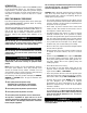
IMPORTANT SAFETY INSTRUCTIONS Commercial-Industrial-Residential Portable Generator System THESE INSTRUCTIONS – The manufacturer suggests that these rules for safe operation be copied and posted near the unit's SAVE installation site. Safety should be stressed to all operators and potential operators of this equipment. • Never start or stop the unit with electrical loads connected to receptacles AND with connected devices turned ON.
IMPORTANT SAFETY INSTRUCTIONS Commercial-Industrial-Residential Portable Generator System ELECTRICAL HAZARDS EXPLOSION HAZARDS • All generators covered by this manual produce dangerous electrical voltages and can cause fatal electrical shock. Utility power delivers extremely high and dangerous voltages as does the generator when it is in operation. Avoid contact with bare wires, terminals, connections, etc., while the unit is running.
Section 1 – General Information Commercial-Industrial-Residential Portable Generator System 1.1 UNPACKING 1.2 ASSEMBLY • Set the palleted carton on a rigid flat surface. • Remove staples along bottom of carton that fasten carton to pallet. Open carton from top. The generator requires some assembly prior to using it. If problems arise when assembling the generator, please call the Generator Helpline at 1-800-333-1322. • Remove all packaging material. 1.2.
1.2.3 BATTERY CONNECTION Figure 3 - Battery Connections • The battery shipped with the generator has been provided fully charged. Caution must be taken when connecting the battery. NOTE: A battery may lose some of it’s charge when not in use for prolonged periods of time. • Cut the tie wrap cable holding the RED and BLACK battery cables to the stator. • Connect the RED battery cable to the battery Positive terminal (+).
Section 2 – Operation Commercial-Industrial-Residential Portable Generator System OPERATION 2.1 KNOW THE GENERATOR Read the Owner’s Manual and Safety Rules before operating this generator.
Section 2 – Operation Commercial-Industrial-Residential Portable Generator System 14) Start/Run/Stop Switch – Controls the operation of the generator. 15) Oil Fill – Use this point to add oil to engine. 16) Fuse - 10 Amp (Located at rear of control panel) – Protects the DC control circuit from overload. If this fuse element has melted open the engine will not be able to crank and start. A GFCI receptacle does NOT protect against circuit overloads, short circuits, or shocks.
Section 2 – Operation Commercial-Industrial-Residential Portable Generator System Figure 9 - 120 VAC, 30 Amp Receptacle 2.2.5 12 VOLT DC, 10 AMP RECEPTACLE This receptacle allows you to recharge a 12 Volt automotive or utility style storage battery with the battery charge cables provided. This receptacle can not recharge 6 Volt batteries and can not be used to crank an engine having a discharged battery. See the section "Charging a Battery" (page 13) before attempting to recharge a battery.
Section 2 – Operation Commercial-Industrial-Residential Portable Generator System 2.3 HOW TO USE THE GENERATOR 2.3.2 CONNECTING ELECTRICAL LOADS If you have any problems operating your generator, please call the generator helpline at 1-800-333-1322. DO NOT connect 240 Volt loads to 120 Volt receptacles. DO NOT connect 3-phase loads to the generator. DO NOT connect 50 Hz loads to the generator. 2.3.1 GROUNDING THE GENERATOR • Let engine stabilize and warm up for a few minutes after starting.
Section 2 – Operation Commercial-Industrial-Residential Portable Generator System 2.5 WATTAGE REFERENCE GUIDE Device . . . . . . . . . . . . . . . . . . . . . . .Running Watts *Air Conditioner (12,000 Btu) . . . . . . . . . . . . . . . . .1700 *Air Conditioner (24,000 Btu) . . . . . . . . . . . . . . . . .3800 *Air Conditioner (40,000 Btu) . . . . . . . . . . . . . . . . .6000 Battery Charger (20 Amp) . . . . . . . . . . . . . . . . . . . . .500 Belt Sander (3") . . . . . . . . . . . . . . . . . . . . . .
Section 2 – Operation Commercial-Industrial-Residential Portable Generator System 2.6.2 ADDING GASOLINE ------------- WARNING ------------ WARNING: Never fill fuel tank indoors. Never fill fuel tank when engine is running or hot. DO NOT light a cigarette or smoke when filling the fuel tank. Caution: Do not overfill the fuel tank. Always leave room for fuel expansion. • Use regular UNLEADED gasoline with the generator engine. Do not use premium gasoline. Do not mix oil with gasoline.
Section 2 – Operation Commercial-Industrial-Residential Portable Generator System • Move engine CHOKE knob outward to “Full Choke” position. Figure 17 - Full Choke Position 2.9 AUTOMATIC IDLE CONTROL This feature is designed to greatly improve fuel economy. When this switch is turned “On,” the engine will only run at its normal fast governed engine speed when electrical load is connected. When the load is removed, the engine will run at a reduced speed of 2100 RPM.
Section 2 – Operation Commercial-Industrial-Residential Portable Generator System 2.12 CHARGING A BATTERY DANGER! Storage batteries give off explosive hydrogen gas while recharging. An explosive mixture will remain around the battery for a long time after it has been charged. The slightest spark can ignite the hydrogen and cause an explosion. Such an explosion can shatter the battery and cause blindness or other serious injury.
Section 3 — Maintenance Commercial-Industrial-Residential Portable Generator System 3.1 MAINTENANCE SCHEDULE Follow the calendar intervals. More frequent service is required when operating in adverse conditions noted below.
Section 3 — Maintenance Commercial-Industrial-Residential Portable Generator System 3.3.3 ENGINE MAINTENANCE 3.3 GENERAL RECOMMENDATIONS The warranty of the generator does not cover items that have been subjected to operator abuse or negligence. To receive full value from the warranty, the operator must maintain the generator as instructed in this manual. DANGER! When working on the generator, always disconnect negative cable from battery.
3.3.6 REPLACING THE SPARK PLUG To clean or replace foam pre-cleaner: Use Champion RC14YC spark plug or equivalent. The correct air gap is 1.01 mm (0.040 in.). Replace the plug once each year. This will help your engine start easier and run better. • Remove air cleaner cover, then foam pre-filter. 1. Stop the engine and pull the spark plug wire off of the spark plug. • Clean air cleaner cover before re-installing it. 2. Clean the area around the spark plug and remove it from the cylinder head.
Section 3 — Maintenance Commercial-Industrial-Residential Portable Generator System Figure 21 - Spark Arrestor To adjust valve clearance: • Loosen the rocker jam nut. Use an 10mm allen wrench to turn the pivot ball stud while checking clearance between the rocker arm and the valve stem with a feeler gauge. Correct clearance is 0.002-0.004 inch (0.05-0.1 mm). NOTE: You must hold the rocker arm jam nut in place as you turn the pivot ball stud.
Section 3 — Maintenance Commercial-Industrial-Residential Portable Generator System 3.7 GENERAL 3.9 OTHER STORAGE TIPS: The generator should be started at least once every seven days and be allowed to run at least 30 minutes. If this cannot be done and you must store the unit for more than 30 days, use the following information as a guide to prepare it for storage. • Do not store gasoline from one season to another.
Section 4 — Troubleshooting Commercial-Industrial-Residential Portable Generator System 4.1 TROUBLESHOOTING SYMPTOM CAUSE SOLUTION Engine is running, but no AC output is available. 1. Circuit breaker is open. 2. Poor connection or defective cord set. 3. Connected device is bad. 4. Fault in generator. 1. Reset circuit breaker. 2. Check and repair. 3. Connect another device that is in good condition. 4. Contact Authorized Service Facility. Engine runs good but bogs down when loads are connected. 1. 2.
Section 5 — Electrical Data Commercial-Industrial-Residential Portable Generator System Wiring Diagram, UltraSource Portable Generator – Drawing No. 0G0731 22 120V/30A 120V/30A TWISTLOK TWISTLOK 120V/20A GFCI 0 22 22 LINE G GREEN WHITE LOAD 2 WHITE 1 HOT 4 22 HOT 2 HOT G HOT G WHITE X 1 22 0 3 0 22 3 4 5 44D 11D 0 0 11C 0 WHITE Y 22 22 5 44C 0 22 0 22 22 0 0 22 0 11A 22 0 22 22 11B 44B 44A 44 44 44 30A 44 C.B. 11 0 30A C.B. 11D 30A C.B.
OUTLET 22 IDLE CONTROL TRANSFORMERS STATOR 22 11 11 22 11 44A 22 44 11S 22S RED 11 44 44 55A 1 44 2 66A 4 22S 83 167 229 77A 3 11S 6 2 5 55A 6 55 7 15B 66 9 55 2 TB1 77 CLOSEST TO BEARING 8 BLK BLK 0 86 BA 10 TB2 11 4 12 0 PIN # 83 229 167 15B 0 86 CB1 11S ON/OFF IDLE CONTROL SWITCH 8 55A 22S 162 4 55 77A 66A 0 77 66 6 ELECTRONIC GOVERNOR / ENGINE SHUTDOWN P.C.B.
Section 5 — Electrical Data Commercial-Industrial-Residential Portable Generator System Schematic, UltraSource Portable Generator – Drawing No. 0G0733 POWER WINDING 77A 55A C1-5 66A 11S C1-4 C1-3 11 22S C1-1 44 C1-2 2 6 C1-6 22 10A BATTERY CHARGE WINDING BA FIELD DPE WINDING BATTERY CHARGE WINDING 4 C1-7 0 C1-11 C1-12 I.C. RED 77 55 C1-10 66 C1-9 C1-8 77 I.C.T. 66A 66 22S 11S 22 I.C.T.
Section 6 - Notes Commercial-Industrial-Residential Portable Generator System 23
Section 6 - Notes Commercial-Industrial-Residential Portable Generator System 24
Section 6 - Notes Commercial-Industrial-Residential Portable Generator System 25
Section 7 — Exploded Views and Parts Lists Commercial-Industrial-Residential Portable Generator System GT-990 Engine (Page 1) – Drawing No.
Section 7 — Exploded Views and Parts Lists Commercial-Industrial-Residential Portable Generator System GT-990 Engine (Page 1) – Drawing No. 0E8589-R ITEM PART NO.
Section 7 — Exploded Views and Parts Lists Commercial-Industrial-Residential Portable Generator System GT-990 Engine (Page 2) – Drawing No.
Section 7 — Exploded Views and Parts Lists Commercial-Industrial-Residential Portable Generator System GT-990 Engine (Page 2) – Drawing No.
Section 7 — Exploded Views and Parts Lists Commercial-Industrial-Residential Portable Generator System Generator – Drawing No.
Section 7 — Exploded Views and Parts Lists Commercial-Industrial-Residential Portable Generator System Generator – Drawing No. 0G0742-A ITEM PART NO. QTY. DESCRIPTION ITEM PART NO. QTY.
Section 7 — Exploded Views and Parts Lists Commercial-Industrial-Residential Portable Generator System Control Panel – Drawing No.
Section 7 — Exploded Views and Parts Lists Commercial-Industrial-Residential Portable Generator System Control Panel – Drawing No. 0G0727-B ITEM PART NO. QTY. DESCRIPTION ITEM PART NO. QTY.
Section 7 — Exploded Views and Parts Lists Commercial-Industrial-Residential Portable Generator System Frame, Handle & Wheel Kit – Drawing No.
Section 7 — Exploded Views and Parts Lists Commercial-Industrial-Residential Portable Generator System Frame, Handle & Wheel Kit – Drawing No. 0E0695-B ITEM PART NO. 1 2 3 4 5 6 7 8 9 10 11 12 13 14 15 16 17 18 19 20 21 22 23 24 25 26 27 28 057058 0D5315 0D4570 0D22850SRV 045771 022129 022145 0D4565 0D3545 022287 022473 022097 022127 0388040AK0 0D4575 0D5202 0D5199 029809 0C3168 0D5198 0E0317 027007 0D5303 042909 090388 064101 039214 0D9165 QTY.
Section 8 – Warranty Commercial-Industrial-Residential Portable Generator System CALIFORNIA EMISSION CONTROL WARRANTY STATEMENT YOUR WARRANTY RIGHTS AND OBLIGATIONS The California Air Resources Board (CARB) and Generac Power Systems, Inc. (Generac) are pleased to explain the Emission Control System warranty on your new engine. In California, new off-road Large Spark-Ignition (LSI) engines must be designed, built and equipped to meet the state's stringent anti-smog standards.
Section 8 – Warranty Commercial-Industrial-Residential Portable Generator System EMISSION CONTROL SYSTEM WARRANTY Emission Control System Warranty (ECS warranty) for 2001 and later model year LSI engines: (a) Applicability: This warranty shall apply to 2001 and later model year engines.The ECS Warranty period shall begin on the date the new engine or equipment is purchased by/delivered to its original, end-use purchaser/owner and shall continue for 24 consecutive months thereafter.
Section 8 – Warranty Commercial-Industrial-Residential Portable Generator System GENERAC POWER SYSTEMS “TWO YEAR” LIMITED WARRANTY FOR GUARDIAN® “15,000 WATT PORTABLE GENERATOR” For a period of two years from the date of original sale, Generac Power Systems, Inc. (Generac) warrants its Guardian generator will be free from defects in materials and workmanship for the items and period set forth below.