FIELD SUPPORT MANUAL Guardian - Generation 2 (Gen2)
Guardian Field Support Manual 1. PURPOSE The purpose of this manual is to describe the process for the installation, fault finding and maintenance of Guardian - Generation 2 (Gen 2). Please refer to the Guardian Field Installation Manual (June 2016) for installations of the Guardian Gen 1. All Guardian Gen 2 installations must be completed in accordance with this manual. This document is the standard for Guardian Gen 2 installations.
Guardian Field Support Manual 2. SECTIONS SECTION TITLE 0. Preface and Compliance Certificates 1. Introduction to Guardian Gen 2 2. Installation of Guardian Gen 2 3.
Guardian Field Support Manual 3. REFERENCE DOCUMENTS The below referenced documents can be accessed via the Technical Communication Portal (TCP) at tcp.seeingmachines.com if you require access to the TCP, please make a request via the ‘Apply Here’ button on the TCP website. ITEM TITLE 1. Knowledge Base 2. Installation Checklist 3.
Guardian Field Support Manual 4. FCC COMPLIANCY This device complies with Part 15 of the FCC Rules. Operation is subject to the following two conditions: (1) this device may not cause harmful interference, and (2) this device must accept any interference received, including interference that may cause undesired operation. This product does not contain any user serviceable components.
Guardian Field Support Manual 5. Canada Certification This device complies with Industry Canada’s licence-exempt RSSs. Operation is subject to the following two conditions: (1) This device may not cause interference; and (2) This device must accept any interference, including interference that may cause undesired operation of the device. Le présent appareil est conforme aux CNR d'Industrie Canada applicables aux appareils radio exempts de licence.
FIELD SUPPORT MANUAL Section 1 – Introduction to Guardian Generation 2
Guardian Field Support Manual Table of Contents 1. OVERVIEW ....................................................................................................................................... 3 2. ABBREVIATIONS .............................................................................................................................. 4 3. TERMS ............................................................................................................................................. 7 4.
Guardian Field Support Manual 1. OVERVIEW The aim of this section is to introduce the acronyms, and components of Guardian Generation 2 (Gen 2) Section 1 A certified Guardian Technician must read and understand this section before commencing a physical installation of the System.
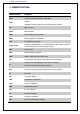
Guardian Field Support Manual 2. ABBREVIATIONS ABBREVIATION MEANING APN Access Point Name-Relates to SIM Card CELL Cellular -Wireless communications via a communications network DC Direct Current Demo Demonstration DSSi Driver Safety System interface EMC Electromagnetic Compatibility FFC Forward Facing Camera Finger Tight Something tightened with your thumb and two fingers. With or without a tool.
Guardian Field Support Manual PPE Personal Protective Equipment (e.g.
Guardian Field Support Manual MEASUREMENTS MEANING A Ampere C Celsius cm Centimeter DC Direct Current ft. Feet g gram GB Gigabyte F Fahrenheit in. Inch kg Kilogram lb.
Guardian Field Support Manual 3. TERMS TERM DEFINITION Black Box Guardian Gen 2 has an inbuilt function to record all footage for a set period. This is known as the Black Box Recorder which is like a Flight Information Recorder - “Black Box”. Certified Technician A Certified Technician is a person who has completed the Seeing Machines training program and has been assessed in the installation and maintenance of a system in a vehicle.
Guardian Field Support Manual System Yaw Refers to the Guardian Gen 2 System but predominately relates to the hardware. The angle in degrees, the In-Cab Sensor (ICS) is mounted left or right in relation to the driver’s head. Value range between -25 to 25 degrees.
Guardian Field Support Manual 4. SAFETY Safety must be considered prior to installing Guardian. You must comply with the client’s site safety policies, processes, arrangements and requirements in place at the site where you will install or maintain the System. If such policies do not exist, it is a requirement to follow the SAFE WORK practices detailed below. For additional Safety related information, contact the local Occupational Health & Safety authority in your country.
Guardian Field Support Manual 5. PACKAGING System Model Type: G2-SY-CON2-1001272 and G2-SY-CON2-1001484 ITEM QTY DESCRIPTION Packaging: Brown Carton Size: 280x270x560mm Weight: 4.7kg Box 1 Inner Cartons 2 Contents: 2 layers of shaped cardboard protecting components.
Guardian Field Support Manual System Model Type: G2-SY-CON2-1002244 ITEM QTY DESCRIPTION IMAGE Packaging: Brown Carton Size: 270x157x560 mm Weight: 3.8kg Box 1 Inner Cartons 2 Contents: 1 layer of shaped cardboard protecting components. Paperwork Markings: 1 Documentation: Installation Checklist Note: Vibration Motor and Forward Facing Camera are packaged separately. Both come in cartons containing 10 items each. Carton size is of similar size to the system carton.
Guardian Field Support Manual 6. STANDARD COMPONENTS ITEM QTY DESCRIPTION Controller Unit Hardware: Connection: This is the main processing unit, all components connect to this unit Size: 182x124x43mm 1 Adjustment: Input voltage: 10 to 30V DC (at the Controller) Function: This is the Processor of the system which runs the entire system. It is rated at IP50 and is not waterproof. The temperature rating is -40C to 65C.
Guardian Field Support Manual Adjustment: Must be squashed flat to be tight, and to be mounted on the opposite side of the Mounting Pan Function: To eliminate loosening from vibration Fastener - Washer: Connection: To fasten Mounting Pan to the vehicle 4 Size: M6 OD 20 SS Flat Washer Adjustment: To be mounted on the opposite side of the Mounting Pan Function: Provide a wider surface area for a stronger hold In-Cab Sensor (ICS) Module Hardware: Connection: To the ICS Cable Size: 200mm x 60mm x 38mm, cable
Guardian Field Support Manual Fastener - Mounting Arm Assembly Bolts: Connection: Connects the arm to the mount and the arm to the ICS module 2 Size: M6 x 12 T20 Security Torx Head Button Screw Adjustment: Allows adjustment of Yaw and Roll using your T20 driver Function: Provides position of the ICS to face to driver depending on dashboard Screw in Hard Mount Connection: Mounting plate for the ICS 1 Size: 63mm diameter Adjustment: Can be orientated for mounting the screws Function: To be used in a Hard
Guardian Field Support Manual Alcohol wipe: Connection: For prepping surface before adhesion. 4 Size: N/A Adjustment: After area is cleaned wait 1 minute for evaporation of alcohol. Function: For adhesive mounts to clean off dust or grease (ICS Adhesive mount, FFC mount, GPS Antenna, 3/4G Antenna) Forward Facing Camera (FFC) Hardware: Forward Facing Camera (FFC) Connection: To the Controller Unit Size: 72 x 41 x 40 mm, cable 7m 1 Adjustment: 1.
Guardian Field Support Manual Hose Clamp Hardware: Connection: To the Vibration Motor / Mounting Plate 2 Size: 320mm Hex Head 8mm Adjustment: Tightening up the hex head will give a stronger clamping connection Function: To clamp the vibration motor to the driver’s seat without the use of screws Vibration Plate Hardware: Connection: To the Vibration Motor Size: 135mm x 28mm 1 Adjustment: Mounting holes are compatible with Generation 1 vibration motor holes Function: This mounting plate is designed to sel
Guardian Field Support Manual Adjustment: Clean surface with Alcohol wipes before Function: To affix GPS antenna to the vehicle Power Cable Hardware: Connection: To the Controller Unit and to the In-line Fuse Holders 1 Size: 5m Adjustment: Can be shortened as required Function: 3 core cable to provide battery, ignition and ground to the Controller Unit In-line Fuse Holder: 2 Connection: To the open-ended side of the Power Cable to be used with Crimps and Joiners on the Battery and Ignition wires as clos
Guardian Field Support Manual Crimp Terminal: Connection: Connects a cut wire to a threaded bolt or screw 3 Size: Blue Ring 6.3mm Adjustment: Automotive crimps must be used to crimp terminal Function: For power connection Crimp Terminal: Connection: Connects a cut wire to a threaded bolt or screw 3 Size: Blue Ring 10mm Adjustment: Automotive crimps must be used to crimp terminal Function: For power connection Zip/Cable Ties: Connection: For cable formation, relief and safe cabling 20 Size: 188mm x 4.
Guardian Field Support Manual 7.
Guardian Field Support Manual 8. REQUIRED TOOLS FOR INSTALLATION TOOL IMAGE 1.
Guardian Field Support Manual Ratchet spanner set 8, 9, 10, 11, 12, 13, 14, 15, 16, 17, 18, 19mm Vice grips Drill bits 2, 4, 6, 7mm Hole Saws 25mm (1in) Multi-meter and leads Wire cutters/Flush Cutters Wire strippers
Guardian Field Support Manual Automotive crimpers Torch / Head Torch Scissors Utility Knife (Confirm site requirements) Cordless Drill Cordless Impact Driver Brush Electrical Tape
FIELD SUPPORT MANUAL Section 2 – Installation of Guardian Generation 2 1
Guardian Field Support Manual – Section 2 Table of Contents 1 OVERVIEW ....................................................................................................................................... 4 2 TECHNICAL COMMUNICATIONS PORTAL (TCP) .............................................................................. 4 3 LAPTOP & SMART PHONE SETUP .................................................................................................... 7 3.1 WINDOWS SETUP..........................
Guardian Field Support Manual – Section 2 7 6.6.1 TROUBLESHOOTING ......................................................... Error! Bookmark not defined. 6.6.2 VEHICLE SWAP ................................................................. Error! Bookmark not defined. 6.6.3 BLACKBOX RECOVERY ...................................................... Error! Bookmark not defined. 6.6.4 CONFIGURATION CHANGE ON A VEHICLE ....................... Error! Bookmark not defined. FINALISING THE INSTALLATION.......
Guardian Field Support Manual – Section 2 1 OVERVIEW This Section describes the process for installing the Guardian Generation 2 system (Guardian Gen 2). This Section is to be followed in sequence, when conducting your first installation. If at the end of a particular ‘Part’, the material states to refer to another ‘Part’, do so and continue until you are referred back to the original ‘Part’ in the Section. Note: A ‘Part’ is a titled block of information inside a Section e.g. Part 5.
Guardian Field Support Manual – Section 2 - Error Code information; and - Online Training Courses. You will access the TCP to complete your online training. Once you are certified you will continue to have access to the TCP (until you are no longer a Certified Technician for SM). The TCP holds your training certifications, and you can log in and download your certificates at any time. The TCP can be accessed at tcp.seeingmachines.com.
Guardian Field Support Manual – Section 2 When the link has opened select the password and change it to your preferred password (something you easily remember) and click “Reset Password”. We use the information in the TCP to communicate changes and updates to the system to our Installation Certified Technicians. We recommend you keep your details up to date within the TCP. How to edit your TCP profile After logging into the TCP, you will see your name in the top right-hand corner of the screen. 1.
Guardian Field Support Manual – Section 2 We use a program called Campaign Monitor to communicate to our Installation network regarding any changes to Guardian. Campaign Monitor allows Seeing Machines to review what actions email recipients take. We can see when recipients open emails AND if they click on any links provided within the email. We can also see if emails are not received and if recipients ask to ‘unsubscribe’ from emails.
Guardian Field Support Manual – Section 2 Start typing “View Network Connections” and click on the corresponding words. Right click on “Ethernet” (this can also be called “Local Area Connection”) and click on “Properties”. 1. Scroll down to “Internet Protocol Version 4” and select it. 2. Click on “Properties” once it is correctly selected.
Guardian Field Support Manual – Section 2 1. Select “Use the following IP address:”. 2. In the IP address: field type 192.168.1.2. 3. Click into the subnet mask and it will auto populate to 255.255.255.0. 4. Then click “OK” to save these settings. Note: When the connection is made between the Laptop and Guardian Controller Unit, the Ethernet section will show “Network [#]” where ‘#’ depends on the numbers of networks that have connected to your laptop previously.
Guardian Field Support Manual – Section 2 3.2 MAC OS SETUP MAC OS (X) (Supports OS X) These instructions are for Apple Mac laptops. These instructions will allow your Apple Mac laptop to communicate with the Controller Unit through the Ethernet Port. If you do not have an Ethernet Port on your computer, you will need to obtain a USB to Ethernet Adapter (not provided by SM). Notes: - If your computer is issued by your employer, you may require an IT Administrator to access the settings.
Guardian Field Support Manual – Section 2 Search or find “Network” and double click on it. 1. Select “Ethernet” in the left-hand panel. 2. Click in the dropdown. Select and click “Manually” to configure the ethernet settings.
Guardian Field Support Manual – Section 2 1. Enter under “IP Address:” 192.168.1.2. 2. Click into the subnet mask and it will auto populate to 255.255.255.0. 3. Click “Apply” to save the settings. Note: When the connection is made between the Laptop and Guardian Processor Unit, the Ethernet section will show Connected. To connect to the Guardian Controller, we recommend using Google Chrome setup on your laptop (instructions at Part 3.3).
Guardian Field Support Manual – Section 2 3.3 CHROME SETUP Google Chrome Setup If you do not have Google Chrome on your laptop you can download the latest version at www.google.com/chrome and follow the prompts. If you already have Google Chrome, you should ensure that you have the latest version downloaded. Once you have an internet connection: - Make sure you have an internet connection. - Open Google Chrome. 1. click on the 3 dots in the top righthand corner. 2. Hover over “Help”. 3.
Guardian Field Support Manual – Section 2 3.4 SMART PHONE SETUP 3.4.1 PHOTO ARCHIVE It is your responsibility to take photos while conducting Guardian installs. This is to protect you if there are issues with the install, or the client complains of damage to the vehicle after installation. You must take photos of any existing damage prior to commencing the install. At the completion of the install, you must take photos of all the installed components.
Guardian Field Support Manual – Section 2 An opening setup screen will appear. 1. Make sure “Backup & Sync” is on. 2. Make sure “(free unlimited storage)” is selected. 3. Make sure your Gmail/Google Account is entered, then click “Done”. To access Google Photos, you can use the app as normal. Alternatively you can go to www.google.com. 1. Sign into your Gmail/Google Account 2. Click on the 9 dots to reveal your app drawer 3.
Guardian Field Support Manual – Section 2 3.5 GUARDIAN SYSTEM RESTORATION REQUIREMENT 3.5.1 USB RECOVERY DONGLE RESTORATION The TCP will have the latest software download required for Guardian to function correctly. Your USB Recovery Dongle will NOT be programmed when you receive it in your installer kit (which will be given to you during your training). As a Installation Certified Technician you will receive notification of new software updates when they are available.
Guardian Field Support Manual – Section 2 During the Installation Wizard the software will automatically ‘look’ for the latest version of software provided internet is available and connected. If there is no internet connected, Guardian will continue to search for any software updates, post-installation.
4 PREPARATION FOR INSTALLATION This chart shows an overview of the steps required to successfully complete an installation Pre-Installation Call Site before arrival • Client has Nano SIM Cards • SIM Cards are activated • Confirm arrival time • Confirm opening hours • Confirm vehicle availability Safety Requirements • Make sure all site safety rules are followed before commencing the installation • Ensure you have all Personal Protection Equipment (PPE) according to site safety rules • Ensure all site indu
Guardian Field Support Manual – Section 2 During Installation Call Support • If you encounter any errors during the install, as prompted by the IVS Wizard, • At the end of the installation. Installation of Hardware • Complete the installation of the system into the vehicle System Checks & Configuration • Follow the IVS Wizard steps and confirm successful completion • Confirm the ICS is in the correct position.
Guardian Field Support Manual – Section 2 Post Installation Paperwork • Scan or photograph the paperwork for your records • Complete Job Card and submit to SM Support Store Photos • Archive photos for you to recall if needed • If you’re using Google Photos (or similar) allow a Wi-Fi connection to upload the photos
5 PRODUCT INSTALLATION The following instructions will allow you to install the Guardian Generation 2. Some general considerations for installs are as follows: 1. You should make sure that you are comfortable with where the cables will run. It is recommended that you conduct a ‘mock’ cable run to ensure that there is enough slack to easily access the Controller. This is to allow for removal when conducting maintenance or troubleshooting tasks. 2.
Guardian Field Support Manual – Section 2 5.
Guardian Field Support Manual – Section 2 5.3 INSTALLATION RECORDS The installation checklist is to be used to record the installation of a specific Guardian system (by SN) in a specific vehicle. This paperwork is a mandatory requirement for the installation of the system and must be retained for your own records. If there is an issue post-install, SM will contact you for your copies. If you are unable to provide these documents, you may be required to correct or remediate the issue at your own cost.
Guardian Field Support Manual – Section 2 Record the OR “P:-XXXXXXXX“ and the “S:-XXXXXXX” Numbers on the Installation Checklist. Important Points to Note: Prior to the installation, the Client, Installer, or the Client Account Manager will notify Support of the list of serial numbers to be installed in the Client’s fleet.
Guardian Field Support Manual – Section 2 5.4 COMPONENT INSTALLATION SPECIFICS 5.4.1 SIM CARD INSTALLATION SIM Card Installation Important Points to Note: Activated SIM cards must be provided prior to commencing the install. The install cannot continue if you do not have activated SIM cards as the system will not be able to connect to a Network. Confirm with the client, that the SIM has been activated with the telecommunications provider.
Guardian Field Support Manual – Section 2 Record the SIM’s serial number on the Installation Checklist (1). Punch out the Nano size SIM (2) SM does not recommend using SIM Cutters to cut the SIM to the correct size. The Nano SIM is to be inserted so that the metal chip is visible (facing up). You must match the cut corner on the SIM card to the matching corner on the tray. Once the SIM is inserted push the tray closed. An audible click should sound when the SIM tray is in the correct position.
Guardian Field Support Manual – Section 2 5.4.2 CONTROLLER UNIT INSTALLATION Controller Unit Image The Contoller Unit When installing the Contoller Unit you will need: The Mounting Pan - You should use at least 3 mounting screws. - It should be orientated so that you can easily access the 2 bottom T20 bolts to slide the controller panel off without removing the Controller Unit from the Mounting Pan.
Guardian Field Support Manual – Section 2 Considerations for mounting are: - Inside the cabin and away from potential water damage. The processor is rated to IP50 and is not waterproof. It cannot be mounted outside of the cabin. Water damage will void warranty. - In a place that is well ventilated (the processor radiates heat from the heat sink). It is rated from -40C to 65C. It is recommended that it is not exposed to direct sunlight.
Guardian Field Support Manual – Section 2 The Fasteners can be tightened up at both the ‘head’ and ‘foot’ of the bolt. The bolt can also be grabbed in place to hold the Mounting Pan allowing you to organise washers and nuts (see image). Adjusting the Mounts: The mounting pan separates into 2 parts. On the Mounting Pan, unscrew the T20 screws anti-clockwise to allow the 2 parts to separate. The two parts can be removed completely, or just loosened to allow the Controller Unit to be removed.
Guardian Field Support Manual – Section 2 5.4.3 IN-CAB SENSOR MODULE INSTALLATION In-Cab Sensor Module (ICS) Image Mounting Location: The In-Cab Sensor (ICS) houses the driver facing camera and the IR Pods and is to be mounted on the dashboard within -25 to 25 degrees of the driver’s straight-ahead position (see image). There is no preference to mounting the ICS to the left or the right of the driver. It is preferable to mount as close to the centre of the driver as possible.
Guardian Field Support Manual – Section 2 The mounting arm provides the Installer with a degree of flexibility to allow for optimal installation. Installers need to consider the effect that vibration can have on the ICS as a result of the way the mounting arm is secured. The KB Article on ICS Mounting Arm Positions provides more details on the preferred way to mount the ICS. Types of Mounting: WARNING: SM recommends using the Hard mount at all times.
Guardian Field Support Manual – Section 2 Soft Mount: The Soft Mount uses a strong adhesive automotive grade double sided tape. The soft mount can only be used once because the tape is single use. If the soft mount is to be used, the Client is to sign a waiver stating that they understand the risks associated with this mounting option. You need to avoid textured, soft or spongy surfaces where possible. You must ensure that the attaching surface has been cleaned.
Guardian Field Support Manual – Section 2 Adjusting the Mounts: The Sensor Mount has 4 points of movement to allow the flexiblility to achieve optimum sensor placement. The T20 security Torx is to be used for the screws on the Sensor Mount. You can partially lock the sensor in place as finer movements can be made using the ‘locking teeth’. When you have the final position, you can hard lock the ICS to the mount.
Guardian Field Support Manual – Section 2 The ICS is designed to be mounted at 0° or lower. 0° is considered to be directly in front of the driver’s head. If the ICS has been mounted above the steering wheel (for example) and it has been rotated in a downward direction, it will result in a negative (-ve) value. If the ICS has been mounted below the dash and it has been rotated in an upward direction, it will result in a positive (+ve) value.
Guardian Field Support Manual – Section 2 Adjusting the Yaw The Yaw should be set between -20 to 20 degrees of the drivers head position. Adjust the angle of the ICS (horizontally left and right) so that the sensor is perpendicular to the head position as shown in the image. Important Points to Note: Ensure the mounting plate is securely mounted to the vehicle so that it will not become a projectile in the event of harsh braking or impact.
Guardian Field Support Manual – Section 2 Mounting Location: You must check the regulations of the country where the vehicle will be operating to ensure that you are complying with mounting to windscreens. Restrictions may vary from country to country. If possible, the FFC is to be mounted within the ‘swept area’ of the windscreen. The swept area is where the wipers clean the winscreen. This will ensure that the FFC has a clear view through the windscreen.
Guardian Field Support Manual – Section 2 Adjusting the FFC: The 1.5mm Allen key is required to lock the camera in position when the optimal camera view has been achieved. A cap is provided to clip over the lock to prevent tampering. It is recommended that the ‘Guardian’ symbol is level when mounted to the windscreen, as shown in the image. Note: You can adjust the FFC more accurately when you complete the IVS Installation Wizard as the video feed will be displayed.
Guardian Field Support Manual – Section 2 5.4.5 3/4G ANTENNA INSTALLATION 3/4G Antenna Mounting Location: The 3/4G antenna must be mounted so that there is a clear line of sight to the sky. The 3/4G antenna can transmit through plastic, wood and fiberglass. It cannot transmit through metal. It is recommended that you mount the antenna as close to a window as possible. The shape of the antenna allows you to mount it close to the windscreen. Mount the 3/4G antenna at least 30cm from the GPS Antenna.
Guardian Field Support Manual – Section 2 Make sure you do not have to move the antenna before you affix it. Relocating the antenna after will destroy the adhesive tape and you will not be able to re-attach it. A high gain antenna can be fitted if needed. SM recommends using an FME male to right angle Fakra D key (colour Bordeaux part number Amphenol 3FA1ENDRJ-C04-3) as the patch lead. Positioning of the High Gain antenna should be done following the guidelines of the chosen antenna. 5.4.
Guardian Field Support Manual – Section 2 There is a separate adheisive pad allows you to attach the GPS to a surface so that it can be orientated to the sky appropriately. Use caution when applying the adhesive tape to the antenna to avoid removing the Serial Number sticker. Prepare the surface using the alcohol wipes provided.
Guardian Field Support Manual – Section 2 There is a magnet located internally on the bottom of the GPS. You may use this to mount the GPS without the need for tape. Note that metal blocks the clear line of site to the sky. It is not reccomended to use the magnet to affix the GPS.
Guardian Field Support Manual – Section 2 5.4.7 VIBRATION MOTOR INSTALLATION Vibration Motor Mounting Location: The Vibration Motor must be mounted on the driver’s seat. It must be located above the adjustment rails and within the red dotted lines as per the image. Do not drill the vibration motor to the seat or frame. This may damage the structural integrity of the seat. The Motor is to be mounted using the bracket supplied.
Guardian Field Support Manual – Section 2 You must mount the Motor to avoid the cable breaking during normal vehicle operation. Therefore, the seat must be able to move freely in all directions. The cabling must be installed with enough slack to allow this movement to occur. It is recommended you follow existing cabling if available. Types of Mounting: Bar Mount: The Vibration Motor has been designed to allow it to mount to different shapes.
Guardian Field Support Manual – Section 2 The hose clamps must be used to mount the Vibration Motor to an appropriate (strong) bar on the seat. Do not mount the Vibration motor to any flexible bars. You can use the 2 hose clamps in any of the 5 slots on the vibration motor (as per the image) Vibration Motor Plate: Mounting to the bar is the preferred option; however, there is a plate that allows you to screw into a surface if required.
Guardian Field Support Manual – Section 2 Use the 2 hose clamps on the outer slots to secure the vibration motor to the mount. Adjusting the Mounts: Using an 8mm socket and your impact driver to tighten the hose clamps (this is the easiest and fastest way to mount). The hose clamps can then be rotated to the final position prior to tightening them. Secure any excess hose clamp with the zip ties provided.
Guardian Field Support Manual – Section 2 The Vibration Motor cable plug connects to the MFC cable. It does not connect straight to the Controller. To reinforce the strength of the cable connector, it is recommended that you double back the wiring across the connection before securing with the provided zip ties. Zip tie the cable to reduce cable breakages (see image). Cut off excess zip tie (as per image).
Guardian Field Support Manual – Section 2 Note: - Where possible, prevent this connection from being in the footwell as it is at risk of being damaged. - The end of the cable has a locking mechanism. Ensure you press the locks before undoing any cables connected to the MFC.
Guardian Field Support Manual – Section 2 5.4.8 POWER CABLE INSTALLATION Power Cable Mounting Location: Ensure that you start at the Controller/Mounting Pan (to ensure you have enough length). Route the Power Cable to the fuse box for the power pickup. You will need to route the cable in such a way that it is not at risk of being damaged during normal vehicle operation. Once you have routed the cable to the fuse box cut off any excess cable with your wire cutters.
Guardian Field Support Manual – Section 2 Types of Connection: The system comes with enough crimps to enable you to crimp together the connections. This is the preferred method. Soldering is permitted; however, you must ensure that your soldering joints are protected from shorting out by covering them with electrical tape or heat shrink. Before power connection: Isolate the vehicle The wiring is as follows; RED WIRE – Battery Terminal (7.5A fuse). YELLOW WIRE - Ignition Terminal (7.5A fuse).
Guardian Field Support Manual – Section 2 To Find a Ground Source (Black Wire): All vehicles have a metal chassis, which is grounded. Most metal bodies around the fuse box are a good ground source; however, you must check the grounding during installation. Ensure the ground connection is free of grease, paint, plastic, corrosion, dirt, dust and is secure.
Guardian Field Support Manual – Section 2 To Find Ignition (Yellow Wire): Connect the positive (+ve) probe of your multimeter to your ignition source and the negative (-ve) probe to the ground pickup point you have identified. Switch your multi-meter to measure ‘DC voltage (V)’. When you turn on the vehicle key to ‘accessories’, the ignition pickup point should display ‘12-24V’ on your multi-meter. It should display ‘0V’ when you turn the key to ‘off’ or ‘lock’.
Guardian Field Support Manual – Section 2 Note: If the systems LED light turns off as soon as the ignition is turned off, then the ignition and battery wires may have been installed incorrectly. You will have to swap the wires. Incorrect power connection can result in a delay in the event data registering to the database and/or ungraceful shutdown which impacts on the system operation. Please refer to the Knowledge Base on how to install vehicles with a ‘non-essentials’ switch.
Guardian Field Support Manual – Section 2 5.4.9 MFC INSTALLTION Multi-Function Cable (MFC) Mounting Location: The MFC connects the system to: - The Vibration Motor. - The Cruise Control Disable Cable (Optional Extra See the TCP). - Mix Integration Cable - Other Fleet Management Systems (FMS) Serial and USB ports. Note that these connections are designed to work with other FMS/Telematics systems, not the FMS system in the truck. The MFC will be plugged into the Controller.
Guardian Field Support Manual – Section 2 The four pin connector plugs into Third Party Fleet Management Systems (FMS) Products (Optional extra) including the Mix Integration Cable. The female micro USB connector plugs into Third Party FMS Products (Optional extra) or any other USB. It cannot be used to connect to a standard USB. The three pin connector plugs into the Cruise Control Disable Cable (CCDC) (Optional extra).
Guardian Field Support Manual – Section 2 5.4.10 CABLING INSTALLATION Installation of Cabling Mounting Location: When installing the cabling, ensure you have enough length, with slack, to reach the Controller. Placement of cables: After all components have been installed and the cable routed correctly, the cables returning to the Controller should be fixed for easy access when the Controller is removed from the Mounting Pan.
Guardian Field Support Manual – Section 2 There are 2 slots cut into the Controllers case for cable relief. You must push a zip tie into the slot (as shown in the image). You must then secure the cables using the zip tie (as shown). You must complete the Software installation before closing the Controller Cover and locking it into the Mounting Pan. With sufficient cable slack, the Controller can be kept close during the Software Installation.
Guardian Field Support Manual – Section 2 6 SOFTWARE SETUP, TESTING & ACTIVATION The system will not be delivered with default software. If any software is delivered with the system, there is a very good chance that it is not the most recent version of the software. You will always be required to apply the most recent version of the software using a programmed USB Recovery Dongle. Additionally, the system software must always be adjusted to accommodate the vehicle setup and the Clients’ specifications.
Guardian Field Support Manual – Section 2 6.1 APPLYING LATEST SOFTWARE TO THE CONTROLLER Software Installation The Software (SW) Installation is to be conducted once you have completed installing all the Hardware components. As the system needs to be configured, all components (except for the processor) need to be in their final location. You will upload the SW using a USB Recovery Dongle (refer to Section 3.5). The latest version of the SW will be available via the TCP in the Knowledge Base.
Guardian Field Support Manual – Section 2 During the re-imaging process the status light on the face of the ICS will flash bright white (with blue tint). When the process has completed the status light will then transition to a steady bright green indicating it has completed successfully. If the re-imaging has failed, the face of the ICS will flash bright red with a repeated ‘chirp’ sound (no image for this status). When the system has stopped flashing, remove the USB Recovery Dongle.
Guardian Field Support Manual – Section 2 Identify the Ethernet cable and the USB to Ethernet adaptor from your Installer Kit (not provided in the system box). Plug them both together to create your access cable. Plug the Ethernet cable into your Laptop Ethernet Port. Plug the USB adaptor plug into the Guardian Controller. Before starting the IVS Installation Wizard ensure: - All peripherals are plugged in to the controller.
Guardian Field Support Manual – Section 2 Note: If the connection fails, check the icon in your System Tray (in the bottom right) and wait until the ‘Unidentified Network’ symbol appears. This will mean that the Controller is ready to connect. Try the previous step again. This setup assumes a standard installation using a SIM card with a USA based provider ‘AT&T’ used as the example provider.
Guardian Field Support Manual – Section 2 Tick the Health and Safety Agreement, which confirms that you have conducted a Health and Safety Check prior to commencing the installation. You will not be able to continue until you have accepted this agreement. Click ‘Continue’ to move to Step 2. Step 2 – Config and eJSON Upload During this step, you will load the Client’s configuration file and the eJSON file (both you will have received in the SW package prior to arriving at site).
Guardian Field Support Manual – Section 2 Click ‘Continue’. Step 3 – Network Connection This step allows you to enter the information for the SIM card to allow the processor to communicate with a cellular Network. The system will automatically Detect the SIM card (1) and will present a green tick when it is successful. Note: If the detection is not successful, a red “X” will appear with an error stating the SIM is missing.
Guardian Field Support Manual – Section 2 settings or call 24/7 Support. Use the Information button when talking to the Support Technician. Note: The bars represent the signal strength of the SIM card. The bars represent the following: 1. Red, one signal bar – 0 to 10% 2. Red, two signal bars – 11 to 20% 3. Yellow, three signal bars – 21 to 50% 4. Green, four signal bars – 51 to 75% 5.
Guardian Field Support Manual – Section 2 Step 5 – Time This step verifies that the GPS, System, or Network time is correct. The time will always be presented in UTC. There are articles on the Knowledge Base to help you work out the correct UTC. Use the Confirmation prompt to verify the time and date presented are accurate.
Guardian Field Support Manual – Section 2 “Save Configuration” and select ‘System Reboot’. The system will take approx. 2 minutes to reboot. Once the reboot has completed, proceed to the next step. If a Mix Integration cable is not installed, move directly to the next step. Third Party Event Relay Signal: 6.3 Third Party Event Relay Signal If a Cruise Control Disable Cable is installed, the cruise control can be disabled by the triggering of any of the events listed on this page.
Guardian Field Support Manual – Section 2 Rotation Example (90°): Once set using the slider (if necessary), select “Save Rotation” and select ‘System Reboot’. The system will take approx. 2 minutes to reboot. You will notice the ICS video feed is longer once the reboot is complete and the page refreshes.
Guardian Field Support Manual – Section 2 7.2 Camera ICS Angle (Pitch and Yaw) There are two ways to set the camera: 1. Using the Auto Calibration function (preferred). 2. Using the sliders for Pitch and Yaw (can be used if the Auto Calibration is not functioning properly). 1. Using Auto Calibration to set Pitch and Yaw Using the button ‘Configure Suggested ICS Angles’, select ‘Start’. You will be prompted to get into a typical driving position (facing the road) and given 5 seconds to get steady.
Guardian Field Support Manual – Section 2 2. Pitch and Yaw using sliders: Use the slider bars to adjust the Pitch and Yaw based on the feedback provided by the live calibration graphs (located to the right of the live feed). The graph should be at or as close to zero when you are in the normal driving position. Select “Save” any time an adjustment is made prior to reviewing the calibration graphs.
Guardian Field Support Manual – Section 2 Create Distraction: Step 8 – Authentication Status This step verifies that the system is Authenticated on the AWS server. The system will work through these steps automatically. When all boxes are green, and ticks appear you can proceed to the next step. If at any point you are unable to get a successful message on a step in the Authentication status, call Seeing Machines to ensure there is no issue on the server.
Guardian Field Support Manual – Section 2 Step 9 – Review This step confirms that all previous steps are complete and will indicate if an error has been detected (yellow or red symbols). If you see red X’s against any steps, you will have to return to that step (using the Icon button on the top or to the left) and conduct troubleshooting. Alternatively, you can call 24/7 Support for assistance.
Guardian Field Support Manual – Section 2 72
Guardian Field Support Manual – Section 2 6.3 SYSTEM CHECKS System Checks After the Installation Wizard been completed, you need to complete some system checks to ensure the system is running optimally. Users are required to navigate to the Dashboard page in order to complete these System Checks. \ 73
Guardian Field Support Manual – Section 2 Tracking Tests: In the ICS Diagnostics tab, make final adjustments to the ICS to ensure that tracking is maintained in multiple seating positions (high, low, close, further away etc). Forward Facing Camera Position: In the ICS Diagnostics tab, observe the FFC video feed. Bonnet - Adjust the camera so that: • The top of the image sees the horizon. • The bottom of the image sees the top of the bonnet.
Guardian Field Support Manual – Section 2 The vehicle can be turned off 75
Guardian Field Support Manual – Section 2 To remove your USB to Ethernet adaptor you will need to lift the release pin on the Controllers USB port, and pull out the USB to Ethernet Adaptor. Take care when removing the adaptor.
Guardian Field Support Manual – Section 2 Then pull out the USB port Note: Any USB port with the 2 square holes shown in this image will lock into the Controller USB devices without these holes won’t latch. This concludes the software setup.
Guardian Field Support Manual – Section 2 6.4 24/7 SUPPORT DETAILS 24/7 Support Center System Registration | Configuration | Troubleshooting support@seeingmachines.com USA: +1 855 377 4636 Australia: +61 2 6108 4313 Mexico: +1 520 838 8138 UK: +44 808 164 5774 South America: +56 2 2938 1718 Technical Communications Portal Support Manuals | Updates | Knowledge Base | Resources tcp.seeingmachines.com 6.
Guardian Field Support Manual – Section 2 - Any optional extras installed Y/N. The support team will give you a status of what they see over the network to make sure it is running correctly. Then an email will be sent to you confirming the installation. You will need to reply to this email with a scanned copy (this can be a photo) of the Installation Checklist, this is required for proof of warranty. The Allocation setup is now complete, you can now finish the installation.
Guardian Field Support Manual – Section 2 7 FINALISING THE INSTALLATION Finalising the Installation Note: These activities should be completed before leaving the vehicle, but after completing the rest of the install. Tuck all the cables in to the relief and slide the cover plate into position.
Guardian Field Support Manual – Section 2 Screw the T20 bolts to lock the Controller Cover onto the Controller. Place the controller in the Mounting Pan and screw the T20 Mounting Pan screws tight. Be respectful to the vehicle owner/driver and leave the vehicle the way you found it. Remove any off cuts and sweep out any shavings you may have left behind. All packaging (besides the plastic bags) is recyclable.
Guardian Field Support Manual – Section 2 7.1 FINAL QA Final QA At the end of the installation a final Quality Assurance (QA) check is required to be conducted. You must check the following: 1. All components of the system have been installed. 2. Cables are zip tied, excess lengths are removed, and the cables do not interfere with the normal function of the vehicle. 3. Cables are hidden from view (as much as possible). 4. All vehicle pieces and fasteners are returned to the correct place on the vehicle.