
Product Manual
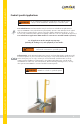


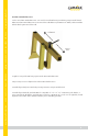

Ø: Total Working Angle
X: Working Distance
Along Leading Edge
Y: Distance From
Leading Edge
X
Y
ø
X
Leading Edge
Guardian Fall Protection 6305 S. 231st St., Kent, WA 98032 phone: (800) 466-6385 fax: (800) 670-7892 www.guardianfall.com
4
Components and Specifications
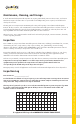
Correct Anchorage Positioning:
This chart details allowable working zones required
to reduce risk of swing falls and improper side loading.
ALWAYS adhere to information specified by chart.
Anchor Distance
From
Leading Edge (Y)
Working Distance
Along Roof Edge
(Either Direction) (X)
Working Angle
From
Perpendicular (Ø)
6’
10’
15’
20’
25’
30’
35’
40’
45’
50’
55’
60’
8’
9’ - 9”
11’ - 7”
13’ - 3”
14’ - 6”
16’
17’ - 2”
18’ - 3”
19’ - 4”
19’ - 10”
21’ - 4”
22’ - 3”
53°
45°
38°
33°
30°
28°
26°
24°
23°
21°
21°
21°
For example, if the anchorage connector is 6’ from the leading
edge (Y), the working distance (X) is 8’ in each direction from
the perpendicular, which translates to a 53° working angle.
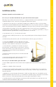
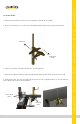
Carriage Bolt
Guardrail Post
Installation Location
Slide Assemblies
Materials: galvanized steel.
#15192: Trench Box Anchor
Type A anchorage connector.
Minimum permitted service temperature: -30° F.
5,000 lb. MBS (minimum breaking strength).
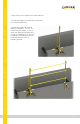
#15193: Trench Box Guardrail Receiver
PFAS Connection Point
Anchor Mast
Guardrail Post
Installation Location
Adjustment
Clamps