
Instructions

PSW Series User Manual
136
Timing diagrams
Below are 4 example timing diagrams covering
a number fo scenarios. Note that pins 18~22 are
all active low.
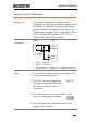
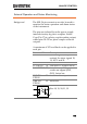
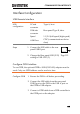
CV MODE:
Output turned on
The diagram below shows the timing diagram
when the output is turned on when the PSW is
set to CV mode.
CV status
H
L
CC status
H
L
Output status
H
L
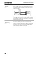
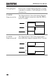
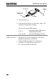
CV MODE:
Output turned off
The diagram below shows the output status
lines when the output is turned off in CV mode.
CV status
H
L
CC status
H
L
Output status
OFF
ON