Arbitrary Function Generator Module AFG-125 / 225 / 125P / 225P QUICK START GUIDE GW INSTEK PART NO.
This manual contains proprietary information, which is protected by copyright. All rights are reserved. No part of this manual may be photocopied, reproduced or translated to another language without prior written consent of Good Will Corporation. The information in this manual was correct at the time of printing. However, Good Will continues to improve its products and therefore reserves the right to change the specifications, equipment, and maintenance procedures at any time without notice.
OVERVIEW The AFG-125/225/125P/225P are arbitrary function generator modules for use with the GDS-2000A series DSOs. The options require the DS2-FH1 module extension bay to secure the module to the DSO. This Quick Start Guide gives a quick overview to the features, installation and basic operation for the AFG125/225/125P/225P. See the user manual for further details. The AFG-125P & 225P also incorporate a power supply output with a selectable voltage output of 2.5, 3.3 or 5V.
Front & Rear Panel Front Power Supply Status LEDs GND SYNC Output WP CH1 Output V V V Negative Output Power Supply Status LEDs Negative Output GND Positive Output SYNC Ouput CH1 Output CH2 Output Positive Output CH2 Output Indicates the state of the power supply (AFG-125P/225P only). Negative output port. Ground port Positive output port Sync signal output.
Installation AFG APP Installation The AFG-125/225 modules require a separate APP installation. 1. Load the AFG.gz APP file onto a USB flash drive. Insert the USB flash drive into the USB slot on the front panel. 2. Press Utility > File Utilities. Select the AFG.gz file on the USB flash drive. 3. Press 4. After the installation has completed, restart the oscilloscope. twice to install the AFG APP.
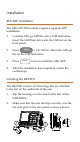
Installing the AFG-125/225 Module The AFG-125/225 modules are installed into the area that is left between both of the DS2-FH1 housings. 1. Slide the module into the slot that was created between the DS2-FH1 housings. The front of the module should be facing forwards. 2. Make sure the module is secure. The module will click into place when it is inserted properly. 3. Make sure the GDS-2000A is turned off before proceeding. 4.
Removing an Installed Module 1. At the rear of the housings are two tabs. Pull both tabs outwards. 2. The module can now be slid out from the housing. USB Configuration The USB Device port needs to be configured to provide power for the AFG-125/225 if an external power supply is not used. 1. As shown previously in the “Installing the AFG125/225 Module” section, connect the GTL-254 USB cable. 2. Press the Utility key and select USB Device Port > USB Power.
Accessing the Arbitrary Function Generator Like all options, the AFG-125/225 options can be accessed with the Option key. O 1. Press the key and select AFG. The AFG-125/225 is now ready to be used. Basic Waveform Selection The AFG-125/225 options have five selectable basic waveforms. 1. Select the output channel by pressing Signal 1 Setup or Signal 2 Setup. 2. Press Waveform Mode and select a waveform type from the side menu. Sine, Square, Pulse, Ramp, Noise 3.
ARB Waveform The following will describe how to create and output an arbitrary waveform. 1. Select the output channel by pressing Signal 1 Setup or Signal 2 Setup. 2. Press ARB from the bottom menu. Press ARB on the side menu and toggle ARB On. 3. Press Edit. 4. Press Edit Method and select the method to edit the arbitrary waveform. Point/Line: Creates pulses of a user-defined length and amplitude. Diagonal: Creates a diagonal line between Addr1/Data1 and Addr2/Data2.
Modulation The following will describe how to modulate a carrier waveform (shape) with the basic waveform shown previously. 1. Select a basic waveform as shown previously. This will be used as the modulating (baseband) signal. 2. Press MOD from the bottom menu. Press MOD on the side menu and toggle MOD On. 3. Select the type of modulation on the side menu: AM, FM, FSK, PM, SUM. 4. Set the parameters for the chosen modulation type from the side menu.
Burst Modulation The following will describe how to create a burst waveform. 1. Press Burst from the bottom menu. Press Burst on the side menu and toggle Burst On. 2. Press N Cycle set the burst parameters. 3. Choose Infinite for an infinite number of burst cycles or press Cycle to set the number of burst cycles for each period. 4. Press Phase to set the phase of the burst. 5. Press Period to set the period of each burst cycle in seconds (not for infinite). 6.
5. To toggle the load impedance between 50Ω and High Z, press Load. 6. For basic waveforms, press Phase to set the output phase. 7. On dual channel models, both output channels can be phase-synchronized by pressing the S_Phase soft-key. State Display The State Display function gives an overview of the arbitrary function generator settings for both channels. 1. Press State Disp to toggle the State Display on. The State Display screen will appear in the center of the display.
Dual Channel (AFG-225/225P only) The following will describe the basic 2 channel functions. Ensure both channels have already been turned on in the Signal 1 Setup/ Signal 2 Setup menus. 1. Press UTIL > Dual Chan from the first level of the AFG menu level. 2. From the side menu choose the relevant tracking functions: Freq Cpl turns frequency coupling on and sets the type of frequency coupling: Offset, Ratio Ampl Cpl turns amplitude coupling on or off.
1. Press UTIL > Sync Setup from the first level of the AFG menu level. 2. Press Sync and toggle Sync on. 3. Press Source and choose Signal 1 or Signal 2 as the source signal to follow. 4. Press Mode and select the SYNC signal mode: 5. Marker forces the marker signal to be the basis of the SYNC signal. Carrier forces the carrier waveform to be the basis of the SYNC signal. Press Polarity and select the SYNC signal polarity. Normal for normal polarity. Inverted for inverted polarity.