
User guide

GAD-201G user manual
7
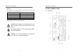
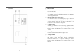
z Rear Panel
GAD-201G user manual
8
(1) INPUT terminal
The terminal is used commonly for the measurements of distortion
factor and AC voltage.
(2) AUTO and HOLD function control
The pushbutton is used for automatic measurement or holding the
desired range during testing.
(3) Function and Frequency range selector
The selectors are used to set a basic frequency range of distortion
factor. Simultaneously use the frequency knob referring to (15) to
set a basic frequency range, then, press the spot button and one of
three buttons to select a desired spot frequency.
(4) X-output terminal
A binding post terminal is used for observing signal waveforms.
Connect the terminal to the “X” input of oscilloscope to observe
Lissajous’s figure. The full scale position of output voltage is about
1V rms.
(5) GND output terminal
Ground the terminal when the X and Y output is used.
(6) Y-output terminal
The terminal is used to observe signal waveforms, which is used as a
total harmonic signal output during distortion measurement.
Connect the terminal to the “Y” input of oscilloscope to observe
Lissajous’s figure. The full scale position of output voltage is about
0.5V rms.