Please read this instruction manual before using the meter and keep it properly for contingent use. PRECAUTION: To avoid danger and damage happened during operation, the following symbols are used as points for attention. :Warning: Improper use of the meter may bring hurt or even death to body. Please read the operation carefully. :Caution: Improper use of the meter may bring hurt or even death to body. Please read the operation carefully.
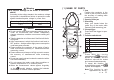
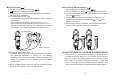
( 1 ) NAME OF PARTS Warning j Jaw 4 To prevent damage to the meter or electrical shock! According to the safety standard, the maximum voltage input power is classified as follows to protect the users against transient impulse voltage in power lines. 2 1 Over-voltage Category (CAT.) Maximum input voltage CAT II 600V 3 Caution 1 Do not use the meter near equipment emitting noise or under an environment with sudden temperature change; otherwise, unstable or erroneous reading will appear.
7 SELECT key Transform between diode and continuity check.
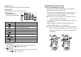
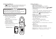
n AC Voltage Measurement ( V ) n Resistance Measurement ( Measuring range: 2V-600V (4 ranges, auto-ranging) 1.Set the function switch knob on V 2.Plug the black test lead into COM terminal and the red one into + terminal 3.Connect the test leads to the cir c uit under test and then read the value when it stabilizes 4.The meter will choose the appropriate range to measure automatically 5.When measurement finished, set the function switch knob on OFF position to turn off t he meter.
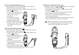
n Diode Check ( n Continuity Measurement ( ) 1.Set the function switch knob on 2. Symbol will appear on the LCD 3.Connect the test leads to the diode and then read the value when it stabilizes (A)Forward-bias Diode Test Connect black test lead to the cathode and red one to the anode Silicon diode value reading approximate 0.5~0.7V Germanium diode value reading approximate 0.5~0.7V Note that reading close to 0V represents a shortcircuit and "OL" symbol indicates an open-circuit. ) 1.
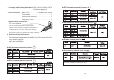
(6) Specification (4) Replacing Batteries If symbols appears, the batteries fall below the normal operation voltage. Replace them with 2 new batteries. (Standard UM-4 or R03 AAA batteries) CAUTION l Before replacing batteries, make sure to disconnect the clamp meter from the circuit under test. l Replace two new batteries at the same time, and make sure you put the batteries at correct polarities. (5) Battery Replacement Steps 1.Abort the measuring action 2.Turn the function switch knob back to OFF 3.
Comply with Safety Standard: IEC 61010-1 600V CAT ll Pollution degree 2 AAA 1.5V ..............2 (inside the case) l Accessories: Test leads.......................................1 Instruction manual ..........................1 Carrying case.................................1 l Optional Accessories: AC Line Splitter l (Direct measuring with no necessity to split the wire away by negative and positive independently.