
User manual

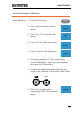
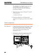
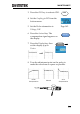
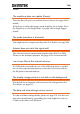
Table Of Contents
- SAFETY INSTRUCTIONS
- GETTING STARTED
- QUICK REFERENCE
- Menu Tree / Operation Shortcuts
- Convention
- Acquire Key
- Acquire Key - Segments
- Autoset Key
- CH1 ~ 4 Key
- Cursor Key
- Display Key
- Help Key
- Math Key
- Measure Key
- Hardcopy Key
- Run/Stop Key
- REF Key
- Save/Recall Key
- Test Key
- Test Key – Go-NoGo
- Trigger Type Menu
- Trigger Edge Menu
- Trigger Delay Menu
- Trigger Pulse Width Menu
- Trigger Video Menu
- Trigger Pulse Runt Menu
- Trigger Rise & Fall Menu
- Trigger Timeout Menu
- Utility Key
- Utility Key – I/O
- Utility Key – File Utilities
- Utility Key – Wave Generator - Demo Outputs
- Search - Edge
- Search – Pulse Width
- Search - Runt
- Search – Rise/Fall Time
- Zoom Key
- Option Key
- Default Settings
- Built-in Help
- Menu Tree / Operation Shortcuts
- MEASUREMENT
- CONFIGURATION
- OPTIONAL SOFTWARE and APPS.
- SAVE/RECALL
- FILE UTILITIES
- HARDCOPY KEY
- REMOTE CONTROL CONFIG
- MAINTENANCE
- FAQ
- I connected the signal but it does not appear on the display.
- I want to remove the (Measurement result / FFT result / Help contents) from the display.
- The waveform does not update (frozen).
- The probe waveform is distorted.
- Autoset does not catch the signal well.
- I can’t save files to the internal memory.
- The display image printout is too dark on the background.
- The date and time settings are not correct.
- The accuracy does not match the specification.
- APPENDIX
- INDEX

GDS-2000A Series User Manual
244
The calibration for Channel 1 starts and ends
automatically, in less than 5 minutes. A
message is displayed when the calibration
procedure has ended.
9. Repeat the above step for Channel 2, 3* and 4*
when prompted.
*4 channel models only.
10. When the calibration for all channels has
completed, the display goes back to the default
state.
Probe Compensation
Panel Operation
1. Connect the probe between the Channel 1 input
and the probe compensation output (Demo 3
output, by default set as 2Vp-p, 1kHz square
wave) on the front panel. Set the probe
attenuation to x10.
2. Alternatively, the probe compensation signal
can be changed. See page 171 for details.
POSITION
CH1
Demo
x1
x10
X
10
X
1
CH1
Demo