
User manual
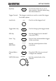
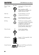
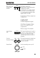
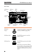
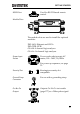
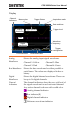
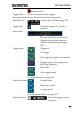
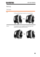

Table Of Contents
- SAFETY INSTRUCTIONS
- GETTING STARTED
- QUICK REFERENCE
- Menu Tree / Operation Shortcuts
- Convention
- Acquire Key
- Acquire Key - Segments
- Autoset Key
- CH1 ~ 4 Key
- Cursor Key
- Display Key
- Help Key
- Math Key
- Measure Key
- Hardcopy Key
- Run/Stop Key
- REF Key
- Save/Recall Key
- Test Key
- Test Key – Go-NoGo
- Trigger Type Menu
- Trigger Edge Menu
- Trigger Delay Menu
- Trigger Pulse Width Menu
- Trigger Video Menu
- Trigger Pulse Runt Menu
- Trigger Rise & Fall Menu
- Trigger Timeout Menu
- Utility Key
- Utility Key – I/O
- Utility Key – File Utilities
- Utility Key – Wave Generator - Demo Outputs
- Search - Edge
- Search – Pulse Width
- Search - Runt
- Search – Rise/Fall Time
- Zoom Key
- Option Key
- Default Settings
- Built-in Help
- Menu Tree / Operation Shortcuts
- MEASUREMENT
- CONFIGURATION
- OPTIONAL SOFTWARE and APPS.
- SAVE/RECALL
- FILE UTILITIES
- HARDCOPY KEY
- REMOTE CONTROL CONFIG
- MAINTENANCE
- FAQ
- I connected the signal but it does not appear on the display.
- I want to remove the (Measurement result / FFT result / Help contents) from the display.
- The waveform does not update (frozen).
- The probe waveform is distorted.
- Autoset does not catch the signal well.
- I can’t save files to the internal memory.
- The display image printout is too dark on the background.
- The date and time settings are not correct.
- The accuracy does not match the specification.
- APPENDIX
- INDEX

GDS-2000A Series User Manual
26
Display
Memory bar
Digital
waveforms
Analog
Waveforms
Bus
Channel status Horizontal status
Trigger
configuration
Waveform
frequency
Date and time
Trigger position
Acquisition modeTrigger Status
Trigger level
Channel
Indicators
Analog
Waveforms
Shows the analog input signal waveforms.
Channel 1: Yellow
Channel 2: Blue
Channel 3: Pink
Channel 4: Green
Bus Waveforms
Shows the bus waveforms for either parallel or
serial buses. The values are displayed in hex or
binary.
Digital
Waveforms
Shows the digital channel waveforms. There can
be up to 16 digital channels.
Channel
Indicators
The channel indicators show the zero volt level of
the signal waveform for each activated channel.
Any active channel is shown with a solid color.
Analog channel indicator
Bus indicator(B)
Digital channel indicator
Reference waveform indicator