
User manual

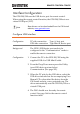
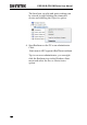
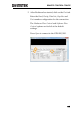
Table Of Contents
- SAFETY INSTRUCTIONS
- GETTING STARTED
- OPERATION
- REMOTE CONTROL CONFIG
- FAQ
- I connected the signal but it does not appear on the display.
- I want to remove the measurement or FFT results from the display.
- The waveform does not update (frozen).
- The probe waveform is distorted.
- Autoset does not catch the signal well.
- The date and time settings are not correct.
- The accuracy does not match the specification.
- APPENDIX
- INDEX

REMOTE CONTROL CONFIG
165
Interface Configuration
The GDS-200/300 uses the USB device port for remote control.
When using the remote control function, the GDS-200/300 acts as a
virtual COM port (VCP).
Note
New drivers can be downloaded from the GW Instek
website, www.gwinstek.com.
Configure USB Interface
Configuration
PC side connection
GDS side connection
Type A, host port
Type Mini-B, device port
Background
The GDS’s USB device port needs to be
configured to the “Communication” mode to
enable the remote connection.
Configuration
1. Connect the PC to the GDS-200/300 using the
supplied USB-A to USB Mini-B cable.
2. From the Drop Down menu press the Utility
icon>USB device port and select
Communication. (See page 102).
3. When the PC asks for the USB driver, select the
USB driver included on the accompanying User
Manual CD or download the driver from the
GW Instek website, www.gwinstek.com. The
driver automatically sets the GDS-200/300 as a
virtual COM port.
4. The DSO should now be ready for remote
control. See page 166 for the remote control
function check.