
User Manual


MULTI-OUTPUT POWER SUPPLY
USER MANUAL
18
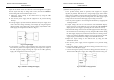
(4) CH3 Power Supply Operation
The CH3 supply provides 2.2~5.2V(GPS-4302/4303) and 3~6V(GPS-4251)
DC output with 3 amps (GPS-3303&4302), 1 amp (GPS-4303) and 2.5 amp
(GPS-4251) current capacity. The supply is ideal for us with TTL circuits
(GPS-3303 5V Fixed).
A. Turn off the power supply and the equipment to be powered during
hook-up.
B. Connect the positive polarity of the device being powered to the red (+)
terminal of the CH3 supply.
C. Connect the negative polarity of the device being powered to the black (-)
terminal of the CH3 supply.
D. If the red OVERLOAD indicator lights, means exceeding load has been
placed on the supply, it will cause voltage and current to drop and interfere
the proper operation of the CH3 supply. To correct this situation, the load
on the supply must be decreased so that no more than 3 amps
(GPS-3303&4302), 1amp (GPS-4303) and 2.5 amps (GPS-4251) of
current are required.
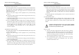
(5) CH4 Power Supply Operation
The CH4 supply provides an 8~15V(GPS-4302/4303/4251) DC output with
a 1 amps current capacity.
A.Turn off the power supply and the equipment to be powered during
hook-up.
B. Connect the positive polarity of the device being powered to the red (+)
terminal of the CH4 supply.
C. Connect the negative polarity of the device being powered to the black (-)
terminal of the CH4 supply.
D. If the red OVERLOAD indicator lights, exceeding load has been placed on
the supply, it will cause voltage and current to drop and interfere proper
operation of the CH4 supply. Under this situation, the load on the supply
must be decreased so that no more than 1 amp of current is required.
MULTI-OUTPUT POWER SUPPLY
USER MANUAL
19
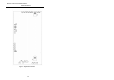
(6) Dynamic Load Operation & Application
A. When select to dynamic load position, the max peak current is at 1.7 times
rating current. The features are only applied for audio circuit of amplifier
and audio production lines. Change the position of wafer J111 of CH1 and
J309 of CH2 from “OFF” to “ON”. Please refer to Fig.6-1 Adjustment
Location.
B. For other application and testing (Safety or CE. etc.), must set the wafer at
“OFF” position
(7) Output ON/OFF Action
The output ON/OFF action is controlled with a single control, the output
switch is pushed on, a high single output is on and output LED is on, while
the output switch is pushed off, or tracking switch is pressed, output will
disable.
CAUTION: The output terminals are for use only with the equipment
which has no accessible live parts. The output terminals should not
be connected to any hazardous live parts.
(8) Fan Control
1) The fan of the power supply will not work upon power on until the
temperature of the heat sink rises up to 32℃±5℃ after adding load
to output terminal. The more the temperature of the heat sink rises,
the more the rolling speed of the fan gets fast. The fastest rolling
speed is when the temperature reaches to 70℃.
2) To avoid damaging the power supply, if the fan fails to work when
the temperature reached to the appropriate value, turn off the
instrument and check the cause.