Precision LCR Meter LCR-800 USER MANUAL GW INSTEK PART NO. 82CR-81900MK1 This manual contains proprietary information, which is protected by copyright. All rights are reserved. No part of this manual may be photocopied, reproduced or translated to another language without prior written consent of the Good Will Instrument company. The information in this manual was correct at the time of printing.
SAFETY INSTRUCTIONS LCR-800 User Manual Table of Contents INTERACE ...................................................................... 111 RS232 Interface Configuration ........... 112 Signal Overview ................................. 116 SAFETY INSTRUCTIONS ................................................... 5 FAQ ............................................................................... 121 GETTING STARTED ......................................................... 10 Main Features ...........
SAFETY INSTRUCTIONS LCR-800 User Manual Safety Guidelines SAFETY INSTRUCTIONS General Guideline CAUTION This chapter contains important safety instructions that you must follow when operating or storing the LCR-800. Read the following before any operation to insure your safety and to keep the LCR-800 in the best possible condition. Safety Symbols Do not place any heavy object on the LCR-800. Avoid severe impact or rough handling that leads to damaging the LCR-800.
SAFETY INSTRUCTIONS Cleaning LCR-800 Operation Environment To ensure fire protection, replace the fuse only with the specified type and rating. Disconnect the power cord before fuse replacement. Make sure the cause of fuse blowout is fixed before fuse replacement. Disconnect the power cord before cleaning. Use a soft cloth dampened in a solution of mild detergent and water. Do not spray any liquid.
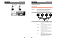
SAFETY INSTRUCTIONS Power cord for the United Kingdom LCR-800 User Manual GETTING STARTED When using the LCR-800 in the United Kingdom, make sure the power cord meets the following safety instructions. NOTE: This lead/appliance must only be wired by competent persons This chapter describes the instrument’s main features, front & rear panels, power up sequence, fixture connections and calibration.
GETTING STARTED Main Features Performance Operation Interface LCR-800 User Manual Model comparison 12Hz ~ 200kHz wide test frequency (LCR-821) 5 digit measurement resolution Test Frequency 821 2V DC bias voltage (12Hz~200kHz) 0.05% basic measurement accuracy (LCR821/819/817) • (12Hz~100kHz) 0.
GETTING STARTED LCR-800 User Manual 7. Bias Front Panel Overview 8.On/Off The On/Off key turns the internal or external bias on or off. 4. PPM Measures Dissipation and Quality factor as PPM. 1. C.V Turns constant voltage mode on or off. 0. R.H LCD Display Function keys Used to turn Range Hold On or Off. 240 by 128, dot matrix LCD display. Assigned to the menu on the right side of the display. -.
GETTING STARTED The Start key is used to start measuring when in manual mode. Start LCR-800 User Manual Rear Panel Overview The start key can also be used to select automatic or manual measuring modes. Hold the Start key for 3 seconds to toggle between auto and manual mode. Force and Sense terminals Current return LSENSE Low potential HSENSE High potential HFORCE Current output LCR-819, LCR-817, LCR-816 Turns the power on or off.
GETTING STARTED Fuse / Power Socket The fuse holder contains the main fuse, 5TT 3A/250V. For fuse replacement details, see page 123. The mains socket accepts the power cord. See page 18 for power-up details. Ground Handler Interface RS-232 Interface LCR-800 User Manual Power Up Tilt stand Low Angle Ensure the stand is up. High Angle Ensure the stand is down. Ground input. Handler interface for binning (LCR-829/827/826 only). RS232 interface (LCR-821).
GETTING STARTED Counterclockwise: bright Clockwise: dark LCR-800 User Manual Fixture Connection Fixture structure Background The standard fixture is a four-wire type (Kelvin 4 wire). The outer terminals (Hforce and Lforce) provide the current and the inner terminals (Hsense and Lsense) measures the potential. Diagram Description 19 20 HFORCE Carries the signal current source. Connected to the + side of the device under test. HSENSE Together with Lsense, monitors the Potential.
GETTING STARTED LCR-800 User Manual H side Fixture connection Panel operation 1. Discharge the test component before connecting the fixture set. L side 2. Connect the Kelvin clip test lead into the front terminals. Line the lead fixture up to the front terminals and slide in. Turn the BNC handle counter clockwise to unlock the fixture. Turn the handles clockwise to lock the fixture. 4.
GETTING STARTED LCR-800 User Manual Zeroing Zeroing calibration Power Supply + Background + LCD EXTERNAL BIAS 30V 200mA MAX MAX CAT Don’t connect Open and short circuit calibration (zeroing) should be performed on a daily basis to correct for cable and fixture errors before taking measurements. When test fixtures or test cables are changed, the zeroing process should be performed again. All data performed during the calibration is stored in the internal memory of the LCR-800.
GETTING STARTED Warning Short circuit LCR-800 User Manual If the test failed, ensure your cables or test fixtures are open and not shorted. Ensure R.H is OFF. After inspection try again. Component Measuring Guidelines The short test will calibrate the short circuit impedance of the cables or test fixtures. This is used for low impedance measurements Background 4. Short the cables or test fixtures using a short thick copper wire if necessary. 5. Press R/L offset in the offset menu. 6.
GETTING STARTED General Capacitors LCR-800 User Manual Air-cored coils Air-cored coils can pick up noise very easily, therefore they should be kept well clear of any test equipment that may contain power transformers or display scan circuitry. Also, keep the coils away from metal objects which may modify inductor characteristics. Iron-cored and ferrite inductor The effective value of iron-cored and ferrite inductors can vary widely with magnetization and test signal level.
BASIC MEASUREMENT LCR-800 User Manual Measurement Item Description BASIC MEASUREMENT In general, two measurement items, primary and secondary, are combined in a single measurement. The following table shows the available combinations. Details of the measurement modes and the circuit theory and formula can be found in the appendix, page 124. Basic Measurement details how to measure individual components and how to configure the LCR-800 settings.
BASIC MEASUREMENT Parameter Configuration LCR-800 User Manual Displayed measurement unit Measurement Speed Measurement units The LCR-800 series support 3 different measurement speeds: slow, medium or fast at approximately 1, 5 or 12 (LCR-829/827/826) measurements per second. The faster the measurement speed, the lower the accuracy. Conversely the slower the measurement speed, the higher the accuracy. The measurement speed and accuracy are dependent on the mode, voltage and frequency.
BASIC MEASUREMENT Panel operation Measurement Modes Measurement mode Panel operation Note LCR-800 User Manual The LCR-800 has a number of different measurement modes. Primary and secondary measurements are displayed on the screen simultaneously. For detailed information regarding the measurement combinations, see the specifications on page 136. The measurement combinations are shown in the table below.
BASIC MEASUREMENT Panel operation LCR-800 User Manual The LCR-821 can provide 504 different frequencies with a 5 digit resolution including decimal places. Any frequency can be keyed from the number pad, and the closest available frequency (of 504) will be selected automatically. The LCR-818/829 has 503 different frequencies and the LCR-817/827 and LCR-816/826 have 489 and 245, respectively. 1. Press the 7/Bias key on the number pad to cycle from internal to external bias.
BASIC MEASUREMENT LCR-800 User Manual 1V 1.1kHz The nearest frequency will be selected from the 504(LCR-281) nominal frequencies, and updated in the display. Here, the nearest frequency to 1.1kHz is 1.0909kHz. Note After the test frequency has been changed, the zeroing must be performed again. See page 24 The voltage is updated in the display. If the voltage entered is outside the allowable voltage range, the nearest voltage is selected.
BASIC MEASUREMENT LCR-800 User Manual Set Range hold PPM will be displayed on the right hand side of the screen, next to mode. Background When DUTs are disconnected from the test cables/fixtures during continuous testing, Range Hold can be used to avoid range switching. This is particularly useful for repetitively testing a number of DUTs. For more information on Range and range hold, see the specifications, page 136. Panel operation 1.
BASIC MEASUREMENT LCR-800 User Manual Inductance (L) Capacitance (C) Impedance (Z) Resistance (R) The average of 10 tests H, mH nF, uF, pF Ω, KΩ Ω, KΩ 3. Press MENU (F5), followed by SORT (F2) and NOM.VAL (F1). 3. Enter the nominal number using the numerical pad, followed by ENTER. Up to 5 digits can be entered. 0.6800mH The number of averages is displayed in the main panel and in the AVGE menu icon after a short processing time. 2. Press EXIT to exit to the main menu.
BASIC MEASUREMENT LCR-800 User Manual Running Measurement Select Automatic measurement Select Single measurement Background Background Panel operation In continuous mode (AUTO), measurements are automatically done and the display is updated according to the measurement speed setting. Measurements can be manually controlled (MANU) or automatically updated (AUTO). In manual mode, one measurement is performed by pressing the start key.
BASIC MEASUREMENT LCR-800 User Manual 4. Store Recall Store or Recall Memory Settings Background Note The LCR-800 series have 100 blocks of memory available for saving settings. All memory is stored using an internal battery. The battery should last 3 years before replacement. If any files cannot be saved or recalled, please contact your local GW Instek distributor to have the battery changed. 1. From the main menu, press MENU, SETTING AND MEMORY. 2. 3.
LCR-800 User Manual 2. Press 1 to recall the calibration settings or 2 to cancel. BIN FUNCTIONS OR CAUTION 3. When the status bar has completed, the calibration settings are recalled. 4. Press EXIT to exit to the main menu. The Handler interface is used to sort components into different bins. The handler menu compares results from a number of different user defined limits. Component sorting can be accomplished in either manual or automatic mode.
BIN FUNCTIONS Bin Summary Menu Bin Summary Menu Overview ................................... 68 Bin Summary/Results................................................. 70 LCR-800 User Manual Binning Menu Handler Menu Overview Mode Setting The mode setting area shows basic settings for the current bin mode.
BIN FUNCTIONS Parameter Delay MANU/ AUTO 1,2,3,4 Handler Menu Delay between each measurement Parameter 0~99999 ms Selects between automatic and manual mode Parameter LCR-800 User Manual Auto, Manu Background Before Bin Sorting, the measurement settings must be configured. Panel operation 1. To access the handler menu, press MENU, SORT, HANDLER from the main menu. INT.B/EXT.B Internal and External voltage Bias Parameter C.V Constant voltage Parameter AVG 2. The Handler menu appears.
BIN FUNCTIONS Circuit Setting LCR-800 User Manual Display Setting Background Use Circuit setting to change the equivalent circuit. Panel Operation 1. 2. Use the arrow menu keys (F1/F2) to move the cursor to CIRCUIT. Background Use the Display setting to change the measurement results as values or bins. Panel Operation 1. Use the arrow menu keys (F1/F2) to move the cursor to Display. 2. Press SET repeatedly to make a selection. VAL.
BIN FUNCTIONS LCR-800 User Manual Select/Run Auto/Manu Sorting Background Set the test mode from manual to automatic. Panel operation 1. Hold the START key for a few seconds to toggle from automatic or manual bin sorting. Voltage Setting Background Set the testing voltage. Panel Operation 1. Use the arrow menu keys (F1/F2) to move the cursor to V (Voltage) 2. Use the number pad to enter a voltage and press ENTER to confirm. 1.
BIN FUNCTIONS Bias Setting LCR-800 User Manual Range Setting Background Set internal or external bias voltage. Panel Operation 1. Background Use the arrow menu keys (F1/F2) to move the cursor to INT.B or EXT.B. 2. Press INT (F3) to use internal biasing. 3. Press EXT (F4) to use external biasing. 4. Use the arrow menu keys to highlight OFF/ON. 5. Press ON (F3) to turn bias voltage on. 6. Press OFF (F4) to turn bias voltage off.
BIN FUNCTIONS 2. Press ON (F3) to turn constant voltage on. Average Setting 3. Press OFF (F4) to turn constant voltage off. Background The average function chooses how many averages (1-255) are used for each measurement. Panel Operation 1. Use the arrow menu keys (F1/F2) to move the cursor to AVERAGE. 2.
BIN FUNCTIONS LCR-800 User Manual Set Bin Menu Set Bin Menu Overview Menu Keys Q_Max Sets the Maximum Q value for the current bin. Q_Min Sets the minimum Q value for the current bin. Scroll up through the menu items Scroll down through the menu items Clears the current bin settings. Goes to the next bin. Exit the menu Bin number Displays the current bin. Bin Settings Configures the nominal value, nominal units and the total amount of bins.
BIN FUNCTIONS 2. Use the arrow menu keys (F1/F2) to move the cursor to SET BIN. 4. Press SET (F3). 5. The Bin menu appears. LCR-800 User Manual Bin Number Background Up to 13 sorting bins can be configured, with a minimum of 1 bin. Panel operation 1. Move the cursor to TOT_BIN in the Bin menu. 2. Use the number pad to enter the amount of sort bins. Ω Ω+ : 4.02% Ω- : 4.
BIN FUNCTIONS LCR-800 User Manual For example: 20 Ω. 2. Use the number pad to enter the maximum percentage value for the current sort bin. For example: Set Max/Min Absolute Limit 10%. Background The maximum and minimum absolute limits of the current bin can be set. The limit units depend on the measurement type, see Sort Type, page 63. Panel operation 1. 2. Move the cursor to MAX to set the absolute maximum limit. 3.
BIN FUNCTIONS Bin Summary Menu Clear Bins Background All the bin settings can be cleared for all the bins. Panel operation 1. 2. Note Press NEXT BIN until BIN1 is the current bin. Press F1 to clear all the bin settings. 4. Press F2(YES ->) to confirm the clear or press F1(NO->) to cancel. Ω F2 Move the cursor to SORT BY in the Bin menu. 3. Bin Summary Menu Overview Bin Parameters Test ResultsFail F4 Test ResultsPass F5 Ω Or Ω Bin settings can only be cleared from Bin1. 1.
BIN FUNCTIONS PHI Indicates that a test result is greater than the maximum limit. LCR-800 User Manual Bin Summary/Results PHI= Primary Hi PLO Indicates that a test result is less than the minimum limit. Background After the bins have been set up (page 61) and sorting has been completed (page 55) the measurement results/summary can be shown. Panel Operation 1. Use the arrow menu keys (F1/F2) to move the cursor to BIN SUM. 2. Press SET to enter the BIN SUM menu. 3.
BIN FUNCTIONS 5. 6. To clear the test results, press CLR followed by F3 (YES->) to confirm. LCR-800 User Manual RS232 REMOTE Press EXIT to exit the bin summary results. The LCR-821 (LCR-816/817/819 as options) includes RS232C remote connectivity. With the RS232 VIEWER software, the LCR meter can be remotely controlled and all test results can be saved to a PC. 71 LCR Setup RS232 Settings .............................................................73 LCR Viewer LCR VIEWER Display Overview .......
RS232 REMOTE LCR Setup LCR-800 User Manual LCR Viewer RS232 Settings LCR VIEWER Display Overview Background RS232 must first be enabled on the LCR-800 before trying to connect with a PC. Panel operation 1. From the main menu, press MENU, SORT AND RS232. 2. Press F1 to turn the RS232 interface ON or F2 to turn RS232 OFF. Background LCR-Viewer mimics the LCR-800 series front panel and operates in a similar manner. Menu Bar Virtual Panel Meter Time ON OR 3.
RS232 REMOTE Message Area LCR-800 User Manual The message area displays the current status of connection, results, files saved and restored. Message Display The Message Display Key turns the Message Area Key on/off. LCR Viewer Connection and File Settings Background Before LCR Viewer can be used the connection settings and file settings must be set appropriately. Please ensure LCR Viewer has been installed. Connection Settings 1. Connect the LCR meter to the PC with an RS232 cable. 2.
RS232 REMOTE LCR-800 User Manual LCR Viewer File Settings Background Note DataBits, StopBits, Parity and Flowcontrol cannot be edited. Note All file menus (File, Option, Data, Help) are restricted in Auto mode. To change to manual mode see page 43 or 80 to change to Manual mode manually or remotely. The LCR Viewer file system stores 10000 test results per file. The files are comprised of the file name identifier and file number identifier.
RS232 REMOTE File Settings 3. 4. Type a file name identifier in the File_Name panel. LCR_ is the default. 5. Check FileNum Reset if you want the file number identifier to be reset to 0001. Then left-click Yes to confirm. Confirm Settings 6. Note Choose a drive and directory from the drop down selections. LCR-800 User Manual LCR Viewer Remote Measurement Background The LCR Viewer Software mimics the LCR-800 meter front panel. Remote operation is identical.
RS232 REMOTE 6. To exit LCR Viewer, press the POWER button or go to the File Exit menu. 7. To turn the message area on or off press the Message button. LCR-800 User Manual View Data Background Up to 10000 test results are stored in each file. Each test result is stored as comma separated variables in a text file. Each test result stores the test number, mode, primary and secondary measurements and the time. 4. Note To exit the data window, click Exit.
RS232 REMOTE LCR-800 User Manual Terminal Connection Configure Terminal Connection 4. Note Background To connect the LCR-800 to a terminal program, follow the instructions below. Connection Settings 1. Connect the LCR meter to the PC with an RS232 cable. 2. Ensure the LCR-800 is set to manual (single) measurement mode. 3. Ensure RS232 has been enabled on Page 73 the LCR meter. 4. Open a terminal program such as MTTTY (Multithreaded TTY). 5. Check the COM port settings on the PC.
RS232 REMOTE 6. Terminal Initiation 7. Connect to the terminal program with the following configuration settings: LCR-800 User Manual Disconnection 10. To disconnect remote control send the following command with ^END^M or ^J^M as the terminal character. COM port (as per PC) Baud rate- 38400 Terminal command: COMU:OFF.
PROGRAMMING LCR-800 User Manual Command forms Commands and queries can be written in either ASCII or hexadecimal. PROGRAMMING Below are examples of ASCII and hexadecimal commands Command overview lists all the LCR-800 commands and command queries. The command syntax section shows you the basic rules you have to apply when using commands. ASCII SORT:NOMV +32.
PROGRAMMING 2D 31 2E 30 30 30 35 As can be seen above, positive input numbers use the ASCII “+” whilst the output will use a “sp” space character to represent a positive number. Negative numbers are identical for both input and output. Output -1.0000 -1.0000 Combining Commands Commands and queries can be combined to form a large continuous command. Each command must be separated with a line feed character< ^END>(or <^J>).
PROGRAMMING LCR-800 User Manual Display VALU Unit Value DELP Delta % The speed command sets the measurement speed of the instrument. The faster the measurement speed the lower the accuracy. This command also queries the current measurement speed.
PROGRAMMING LCR-800 User Manual MAIN:CIRC:PARA<^END> Example MAIN:MODE:RQ<^END^M> Query Example Sets the mode to R/Q (Resistance/Quality factor) Query Syntax Parallel MAIN:CIRC?<^END^M> MAIN:CIRC:PARA<^END> Returns a parallel equivalent circuit as the current setting. MAIN:MODE?<^END^M>or<^J^M> Return String Current measurement mode FREQUENCY MAIN:MODE:RQ<^END> R/Q Set or queries the test frequency.
PROGRAMMING 0.005~1.275 (5 characters, including a 5mV~1.275 decimal) Example MAIN:VOLT 0.005<^END^M> Query Syntax Returns Auto mode as the current measurement mode. Sets the test signal voltage to 5mV. START MAIN:VOLT?<^END^M>or<^J^M> Starts a measurement in manual mode. Return String Voltage MAIN:VOLT :< variable ><^END> (= 0.005~1.275) Returns the test voltage. Query Example LCR-800 User Manual MAIN:VOLT?<^END^M> MAIN:VOLT 0.
PROGRAMMING LCR-800 User Manual Query Example C.V Command/Query Returns the Bias Status (External Bias is on). Turns Constant Voltage on or off. Queries the constant voltage status. Syntax MAIN:BIAS?<^END^M> MAIN:EXTB:ON..<^END> INT.B MAIN:C.V.: <^END^M>or<^J^M> Command/Query Constant Voltage Sets and queries the internal bias. MAIN:INTB:<^END^M>or<^J^M> Syntax OFF. Off Parameter ON.. On Internal Bias MAIN:C.V.:OFF.<^END^M> OFF.
PROGRAMMING Example Query Syntax LCR-800 User Manual MAIN:EXTB:OFF.<^END^M> Turn External Bias off. OPEN MAIN:EXTB?<^END^M>or<^J^M> This command will perform an open circuit calibration. A return string will indicate if the calibration was successful or not. Return String External Bias status Syntax MAIN:EXTB:OFF.<^END> MAIN:EXTB:ON..<^END> Off On Return String Query Example MAIN:EXTB?<^END^M> MAIN:EXTB:ON..<^END> Returns the External Bias status (On). PPM Syntax PPM OFF. Off ON.
PROGRAMMING MEMO:NUMB <^END> (= 1spsp~100) sp=space character Parameter < variable > Nominal Value -XXXXXXX ~ +XXXXXXX Must be any 8 digit +XXXXXX~-XXXXXX character including a (Mode dependant) decimal place and signage (- or +). Example SORT:NOMV –0.12345<^END^M> LCR-800 User Manual Query Example Not Ok. The memory slot is empty, therefore no data to recall. MEMO:NUMB?<^END^M> MEMO:NUMB:100<^END> Data was recalled from memory slot 100.
PROGRAMMING LCR-800 User Manual Example AVERAGE Command/Query Sets the average number from 1~255. The average number indicates how many test samples are used to create an averaged test result. Syntax STEP:AVER <^END^M>or<^J^M> 1.00~255. Note Example Ensure the number has a total of 4 characters. If a number does not use 4 characters, use a “.” and additional zero’s (0) to “pad out” the number. Example 10 = 10.0 STEP:AVER 255.
PROGRAMMING COMU:MONO:819.<^END> LCR-819 COMU:MONO:821.<^END> LCR-821 Query Example Example LEVEL DISPLAY The model number is LCR-816 Command Displays a menu level on the LCR-800 display. Returns the menu level. Query Syntax The On-line function queries the RS232 connection status. Query Syntax COMU:RECO<^END^M> Resume measurement. (recover measurement). COMU:MONO<^END^M> COMU:MONO:816.
PROGRAMMING Test result Any 7 digit ASCII including sp (+) or – Primary measurement value characters and a decimal point. MAIN:PRIM 32.705<^END> Example The primary measurement is 32.705 (primary measurement unit).
PROGRAMMING SECONDARY FACTOR, PRIMARY UNIT, SECONDARY UNIT Measurement MAIN:SECO <^END> Secondary units k, sp kΩ, Ω Example Secondary measurement result is returned along with the primary unit and secondary unit (C/R, L/R only). This measurement is the second measurement displayed after measurements have been started.
INTERACE LCR-800 User Manual RS232 Interface Configuration INTERACE Configure RS-232 interface Connector DB-9, Male Baud rate 38400 (default) This chapter describes basic interface aspects of the RS-232 and Handler interfaces. Parity None Data bit 8 RS232 Interface Configuration Configure RS-232 interface ....................................... 112 Handler interface ...................................................... 114 Stop bit 1 Signal Characteristics Signal Overview ................
INTERACE LCR Meter DB9 Pin Signal Signal DB9 Pin 2 RxD TxD 3 3 TxD RxD 2 4 DTR DSR, DCD 6,1 5 GND GND 5 6,1 DSR, DCD DTR 4 7 RTS CTS 8 8 CTS RTS 7 Handler interface Connection Connect the male DSUB 25 pin cable to the Handler interface socket.
INTERACE Pin11 /O_BIN_11 Go, Assigned BIN 11 Pin12 /O_BIN_12 Go, Assigned BIN 12 Pin13 /O_BIN_13 Go, Assigned BIN 13 Pin14 /O_S_OVER No-Go/D or Q fail Pin15 /O_P_OVER RLC FAIL(O) Pin16 GND GROUND Pin17 VCC VCC Pin18 GND GROUND Pin19 /O_P_HI RLC FAIL(O) Pin20 /O_P_LO RLC FAIL(O) Pin21 /O_S_REJ No-Go/D or Q fail Pin22 /O_INDEX LCR-800 User Manual Signal Overview Background The signal overview section describes the functions and the overall characteristics of the signals used in the ha
INTERACE /O_S_REJ /O_S_OVER /O_EOM Electrical Characteristics The /O_S_REJ or /O_S_OVER signal will go low when the secondary measurement is over D_Max or under D_Min, whilst in C/D , R/Q, C/R or L/R mode. The signals will go high at time T4 Parameter The End of Measurement signal becomes active low when the Bin comparison/assignment has completed. The signal goes high after the next time I_E_TRIG is active low.
INTERACE Handler Timing Background The handler timing characteristics are described in the timing diagram. Times T1 to T6 are described in the relevant tables. LCR-800 User Manual Analog Measurement time T5 Trigger Wait Time T6 After /O_EOM Output Slow 0.012kHz 817ms 0.1kHz 901ms 0.
FAQ LCR-800 User Manual For more information, contact your local dealer or GW Instek at www.gwinstek.com / marketing@goodwill.com.tw. FAQ Q1. What is the correct procedure for Open/Short Zeroing when using the LCR-06A test fixture? A1. The LCR-06A test fixture is very sensitive and thus must be used correctly. For Open Zeroing, make sure that the test fixture wires do not move and that there is nothing in close proximity to the test clips. For Short Zeroing ensure the clips are properly shorted.
APPENDIX LCR-800 User Manual Circuit Theory and Formula APPENDIX Series/Parallel circuit models Background Below are the circuit diagrams and formulas describing the six types of series and parallel equivalent circuits: Capacitive, Inductive and Resistive. The formulas for all the primary and secondary measurement types are also shown. Capacitance (C) Series diagram Fuse Replacement Step 1. Disconnect the power cord and then remove the fuse socket using a flat screwdriver.
APPENDIX Resistance (R) Series diagram Parallel diagram LCR-800 User Manual Resistance (R) and Conductance (G = 1/R) Formula Background Parallel formula Series formula RS RP 1 Q2 RP RS 1 Q 2 Q=quality factor Note Q=quality factor Type Formula Resistance measures how difficult it is for the electricity to flow between two terminals. Conductance is the reciprocal of Resistance and measures how easily the electricity flows.
APPENDIX Capacitance (C) Formula Reactance (X) and Susceptance (B = 1/X) Formula Background Capacitance measures the amount of electronic charge stored between two terminals.
APPENDIX Impedance (Z) and Admittance (Y = 1/Z) Formula Background Note Type Formula Quality factor (Q) and Dissipation factor (D) Formula Impedance measures the total amount of opposition between two terminals in an AC circuit. Admittance is the reciprocal of Impedance and measures how easily the electricity flows in an AC circuit. Admittance is only shown for its relation to impedance. Admittance is not measurable with the LCR-800 series.
APPENDIX Accuracy Definitions Angle (θ) Formula Background The Angle (θ) measures the phase on which Impedance (Z), Admittance (Y), Quality factor (Q), and Dissipation factor (D) are measured. Type Angle (θ) Formula Z S R jX R j L R Q LCR-800 User Manual YP G jB j C 1 1 tan 90 D G j C G j L D tan 90 RS Z cos GP Y cos X S Z sin BP Y sin 1 Q Primary Measurement Readout Error Formula C 2 counts±0.03%+0.
APPENDIX R(L/R) Q≦1 Q≧1 Conditions 2counts + 0.02%[(1+Ka)* or (Rx/Rmax)* or (Rmin/Rx)*] (1+ | Q│)(1+Kb+Kc)+0.03% 2counts + 0.02%[(1+Ka)** or (Lx/Lmax)** or (Lmin/Lx)**] (1+| Q│)(1+Kb+Kc)+0.03% LCR-800 User Manual Table 1 KC (Ranges 1,2,3) Frequency & RMS Voltage factor Voltage 0.03≦V<0.1 0.1≦V<0.25 0.25≦V<1 Frequency 35 0.012≦f<0.03 30 0.030≦f<0.1 25 0.1≦f<0.25 20 0.25≦f<1 1 14 15 1<f≦3 15 3<f≦6 15 6<f≦10 20 10<f≦20 30 20<f≦50 50 50<f≦100 200 Not applicable # 1. if X>Ymax, please select (X/Ymax) 2.
APPENDIX Specifications Table3 Y Range constant- Range Hold Component Inductor Capacitor Range Max Min Max Min Range1 16mH/f 1mH/f 25uF/f 1.6uF/f Range2 256mH/f 16mH/f 1600nF/f 100nF/f Range3 4100mH/f 256mH/f 100nF/f 6.4nF/f Range4* 65H/f 4.1H/f 6400pF/f 400pF/f f= test frequency in kHz * This range is not used above 20 kHz Resistor Max Min 100Ω 6.25Ω 1.6kΩ 0.1kΩ 25.6kΩ 1.6kΩ 410kΩ 25.
APPENDIX Accuracy Basic Accuracy Test Frequency Measurement displays Dissipation 1 ppm ~ 9999 ppm factor (D)+ in ppm Quality 1 ppm ~ 9999 ppm factor (Q)** in ppm DELTA % 0.00001% ~ 99999% *s=series, p=parallel ESR=Rs ** with L or R + with C Note: Only LCR-821 has Z/θ and L/R measurement parameters. If any of these quantities is negative, the “-“ negative indicator is displayed. LCR-821/819/817 R, L, C, Z 0.05%(Basic) D, Q 0.0005(Basic) θ 0.03˚(Basic) LCR-829/827/826/816 R, L, C, Z 0.10%(Basic) D, Q 0.
APPENDIX Power Source Dimensions Weight 100V~240V AC, 50~60Hz/ 400Hz Power Consumption 45 Watts maximum Fuse Slow-blow 5X20 mm, 3A/250V UL/CSA 5TT GMD 330mm (W) × 149mm (H) × 437mm (D) 5.5kg LCR-800 User Manual Line Voltage EC Declaration of Conformity We GOOD WILL INSTRUMENT CO., LTD. No. 7-1, Jhongsing Rd., Tucheng City, Taipei County 236, Taiwan GOOD WILL INSTRUMENT (SUZHOU) CO., LTD. No. 69 Lushan Road, Suzhou New District Jiangsu, China.
INDEX LCR-800 User Manual specification ......................... 136 Display unit settings handler menu ........................ 54 INDEX Absolute limit settings set bin menu ........................... 65 Admittance Dissipation accuracy definition .............. 132 Dissipation factor overview ............................... 130 series/parallel model .......... 124 Caution symbol .........................5 Circuit settings overview ............................... 129 handler menu ................
INDEX wire capacitance .................... 27 Memory specification ......................... 138 Mode settings handler menu ......................... 52 Nominal value set bin menu ........................... 64 Nominal value setting basic measurement ................ 41 Operation environment specification ......................... 138 Parallel circuit selection.......... 33 Percentage limit settings set bin menu ........................... 65 Power source specification .........................
INSTEK LCR METER-RS232 CODE Ver 2.2 2010/05/03 Command Reference z Message Terminator (Last data byte with END message) or : New Line or ASCⅡ Line Feed Character (Hex 0A).
z Initialization 1. Power on the LCR Meter 2. Selects “MANU” mode. How to change MANU mode? Please refer to user manual showing about the panel description (13) in chapter 3. 3. PC sends command COMU?^END^M (or ^J^M) 4. Waiting for LCR Meter response. If LCR Meter response is COMU:ON..^END(or ^J^M) then go to step 5. If LCR Meter response is COMU:OFF.^END(or ^J^M) then check below: (1) LCR Meter‘s baud rate set 38400(default),so PC have to set the same. (2) LCR Meter’s RS232 item have to be set on.
Command String 1 2 3 4 5 6 7 8 9 FUNCTION SPEED Command Syntax MAIN:SPEE:SLOW<^END^M> MAIN:SPEE:MEDI<^END^M> MAIN:SPEE:FAST<^END^M> DISPLAY MAIN:DISP:VALU<^END^M> MAIN:DISP:DELP<^END^M> MAIN:DISP:DELT<^END^M> MODE MAIN:MODE:RQ<^END^M> MAIN:MODE:CD<^END^M> MAIN:MODE:CR<^END^M> MAIN:MODE:LQ<^END^M> MAIN:MODE:LR<^END^M> MAIN:MODE:ZQ<^END^M> CIRCUIT MAIN:CIRC:SERI<^END^M> MAIN:CIRC:PARA<^END^M> FREQUENCY MAIN:FREQ <^END^M> Example: MAIN:FREQ 0.
Query Syntax MAIN:C.V.?< ^END^M> 11 FUNCTION Command Syntax C.V MAIN:C.V.:OFF.< ^END^M> MAIN:C.V.:ON..< ^END^M> BIAS 12 INT.B MAIN:INTB?< ^END^M> 13 EXT.B 14 PPM. 15 OPEN MAIN:INTB:OFF.< ^END^M> MAIN:INTB:ON..< ^END^M> MAIN:EXTB:OFF.< ^END^M> MAIN:EXTB:ON..< ^END^M> MAIN:PPM.:OFF.< ^END^M> MAIN:PPM.:ON..< ^END^M> OFFS:OPEN< ^END^M> 16 SHORT OFFS:SHOR< ^END^M> 17 NOM.VAL 18 RECALL SORT:NOMV< ^END^M> SORT:NOMV?<^END^M> Example: SORT:NOMV +0.12345< ^END^M> SORT:NOMV –0.
19 FUNCTION STORE Command Syntax MEMO:STOR < ^END^M> Example: MEMO:STOR 100.< ^END^M>. 20 AVERAGE 21 RECALL CALIBRATION BAUDRATE SETP:AVER <^END^M> Example: SETP:AVER 255.< ^END^M> STEP:RECA< ^END^M> 22 23 MODE L NO. 24 ONLINE 25 MEASURE HOLD MEASURE RECOVER 26 Query Syntax SETP:AVER?< ^END^M> COMU:< ^END^M> Example: COMU:9600< ^END^M> Query Response NOTE MEMO:STOR <^END> value:1.00 – 100.
FUNCTION 27 LEVEL DISPLAY 28 Primary Factor 29 Secondary Factor & Unit for R/Q,C/D,L/Q 30 Secondary Factor & Unit for C/R 31 Initiation has finished 32 OFF LINE Command Syntax Query Syntax Query Response LEVE:MAIN< ^END^M> LEVE:MENU< ^END^M> LEVE:PARA< ^END^M> LEVE:SORT< ^END^M> LEVE:OFFS< ^END^M> LEVE:MAIN< ^END> LEVE:MENU< ^END> LEVE:PARA< ^END> LEVE:SORT< ^END> LEVE:OFFS< ^END> MAIN:PRIM <^END> Example: MAIN:PRIM 32.705<^END> MAIN:SECO <^END> Example: MAIN:SECO .
Example: ONLINE step 1(power on only) PC send command COMU?< ^END^M> or <^J^M> ASCII CODE = 43 4F 4D 55 3F 0A 0D (Hex format) LCR Meter Response : COMU:ON..
Set Nomval PC send command SORT:NOMV +32.0000< ^END^M> or <^J^M> ASCII CODE = 53 4F 52 54 3A 4E 4F 4D 56 20 2B 33 32 2E 30 30 30 30 0A 0D (Hex format) LCR Meter Response SORT:NOMV 32.0000<^END> ASCII CODE = 53 4F 52 54 3A 4E 4F 4D 56 20 20 33 32 2E 30 30 30 30 0A (Hex format) PC send command SORT:NOMV -32.0000< ^END^M> or <^J^M> ASCII CODE = 53 4F 52 54 3A 4E 4F 4D 56 20 2D 33 32 2E 30 30 30 30 0A 0D (Hex format) LCR Meter Response SORT:NOMV -32.
ASCII CODE = 4D 45 4D 4F 3A 53 54 4F 52 20 31 2E 30 30 0A 0D (Hex format) LCR Meter Response MEMO:STOR 1 <^END> ASCII CODE = 4D 45 4D 4F 3A 53 54 4F 52 20 31 20 20 0A (Hex format) Recall Memory PC send command MEMO:RECA 1.00< ^END^M> or <^J^M> ASCII CODE = 4D 45 4D 4F 3A 52 45 43 41 20 31 2E 30 30 0A 0D (Hex format) LCR Meter Response MEMO:NUMB 1 <^END> ASCII CODE = 4D 45 4D 4F 3A 4E 55 4D 42 20 31 20 20 0A (Hex format) Test Result for Primary Factory LCR Meter Response MAIN:PRIM 32.
LCR Meter Response MAIN:SECO .0045 %<^END> ASCII CODE = 4D 41 49 4E 3A 53 45 43 4F 20 20 2E 30 30 34 35 20 25 0A (Hex format) OFF LINE PC send command COMU:OFF.< ^END^M> or <^J^M> ASCII CODE = 43 4F 4D 55 3A 4F 46 46 2E 0A 0D (Hex format) LCR Meter Response : COMU:OFF.
OPEN Step1: PC send command LEVE:OFFS< ^END^M> or <^J^M> ASCII CODE = 4C 45 56 45 3A 4F 46 46 53 0A 0D (Hex format) LCR Meter Response :. LEVE:OFFS<^END> ASCII CODE = 4C 45 56 45 3A 4F 46 46 53 0A (Hex format) Step2: PC send command OFFS:OPEN< ^END^M> or <^J^M> ASCII CODE = 4F 46 46 53 3A 4F 50 45 4E 0A 0D (Hex format) When open test is ok LCR Meter Response :. OPEN:OK<^END> ASCII CODE = 4F 50 45 4E 3A 4F 4B 0A (Hex format) When open test is fail LCR Meter Response :.
SHORT Step1: PC send command LEVE:OFFS.< ^END^M> or <^J^M> ASCII CODE = 4C 45 56 45 3A 4F 46 46 53 0A 0D (Hex format) LCR Meter Response :. LEVE:OFFS<^END> ASCII CODE = 4C 45 56 45 3A 4F 46 46 53 0A (Hex format) Step2: PC send command OFFS:SHOR< ^END^M> or <^J^M> ASCII CODE = 4F 46 46 53 3A 53 48 4F 52 0A 0D (Hex format) When short test is ok LCR Meter Response :. SHOR:OK<^END> ASCII CODE = 53 48 4F 52 3A 4F 4B 0A (Hex format) When short test is fail LCR Meter Response :.
z How to get test result? Two ways reach to the goal.. 1. Trigger mode is selected to AUTO mode: If the AUTO mode is selected, LCR Meter will send test result to pc after process the measurement automatically. PC doesn’t need to send any command. 2. Trigger mode is selected to MANU mode: If the MANU mode is selected, LCR Meter doesn’t process the measurement and send test result to pc automatically. PC have to send a command of MAIN:STAR^END^M(or ^J^M) to LCR Meter.
z Test Result Format Ex: When LCR Meter have Processed Measurement, then will sequent send 2 command for test result automatically. Refer to below: Ex: When C=1nF,D= .0045 (C/D mode and display mode is VALUE) 1. Primary factor of test result. (It doesn’t include primary's unit). LCR Meter response MAIN:PRIM 1.0000^END ASCII CODE = 4D 41 49 4E 3A 50 52 49 4D 20 20 31 2E 30 30 30 30 0A (Hex format) Positive symbol 2. Secondary factor and primary’s unit LCR Meter response MAIN:SECO .
Ex: When R=1kohm,Q= .0005 (R/Q mode and display mode is VALUE) 1. Primary factor of test result (It doesn’t include primary's unit) LCR Meter response MAIN:PRIM 1.0000^END ASCII CODE = 4D 41 49 4E 3A 50 52 49 4D 20 20 31 2E 30 30 30 30 0A (Hex format) Positive symbol 2. Secondary factor and unit LCR Meter response MAIN:SECO .0005k ^END ASCII CODE = 4D 41 49 4E 3A 53 45 43 4F 20 20 2E 30 30 30 35 6B 20 0A (Hex format) Positive symbol Primary factor’s unit Ex: When R=-1kohm,Q= -.
C/R mode add a secondary factor’s unit Ex: When C=1nF,R= .0045k ohm (C/R mode and display mode is VALUE) 1. Primary factor of test result (It doesn’t include Primary's unit). LCR Meter response MAIN:PRIM 1.0000^END ASCII CODE = 4D 41 49 4E 3A 50 52 49 4D 20 20 31 2E 30 30 30 30 0A (Hex format) Positive symbol 2. Secondary factor and unit LCR Meter response MAIN:SECO .
EX: If the impedance of “Device-under-test” is small than the existing measurement range of the LCR Meters, LCR Meters will send message as below: LCR Meter response PRIM:OV01 ^END ASCII CODE = 50 52 49 4D 3A 4F 56 30 31 20 0A (Hex format) C/R mode add a secondary factor’s unit Ex: When C=.00001nF,R= OVER kohm (C/R mode and display mode is VALUE) 1. Primary factor of test result (It doesn’t include Primary's unit). LCR Meter response MAIN:PRIM .
z Continuous Command When you would like to send two commands or more, you have to send a code between two commands. Refer to below: or <^J> : New Line or ASCⅡ Line Feed Character (Hex 0A). Last Command need add two codes. Refer to below: or <^J> : New Line or ASCⅡ Line Feed Character (Hex 0A). : ASCⅡ Carry Return Character (Hex 0D) Example: Setting Frequency, Voltage and Test Speed PC send command MAIN:FREQ 1.00000< ^END>(or <^J>) MAIN:VOLT 1.
z Off Line Function: PC disconnect with LCR Meter. PC have to send a command COMU:OFF.^END^M( or ^J^M )to LCR Meter. LCR Meter will respond a command COMU:OFF.^END to PC and recover display after receive PC command. Command String: PC sends command COMU:OFF.< ^END^M> or <^J^M> ASCII CODE = 43 4F 4D 55 3A 4F 46 46 2E 0A 0D (Hex format) LCR Meter response: COMU:OFF.