DC Electronic Load PEL-3000 Series QUICK START GUIDE GW INSTEK PART NO.
This manual contains proprietary information, which is protected by copyright. All rights are reserved. No part of this manual may be photocopied, reproduced or translated to another language without prior written consent of Good Will Corporation. The information in this manual was correct at the time of printing. However, Good Will continues to improve its products and therefore reserves the right to change the specifications, equipment, and maintenance procedures at any time without notice.
SAFETY INSTRUCTIONS This section contains the basic safety symbols that may appear on the accompanying User Manual CD or on the instrument. For detailed safety instructions and precautions, please see the Safety Instructions chapter in the user manual CD. Safety Symbols These safety symbols may appear in the user manual or on the instrument. Warning Caution Warning: Identifies conditions or practices that could result in injury or loss of life.
Power Cord for the United Kingdom When using the instrument in the United Kingdom, make sure the power cord meets the following safety instructions. NOTE: This lead/appliance must only be wired by competent persons.
GETTING STARTED The Getting Started chapter introduces the instrument’s main features, appearance, and set up procedure. Overview The PEL-3000 Series is a family of high performance DC electronic loads positioned to test a wide range of different power sources. The DC electronic loads are fully programmable to simulate anything from basic static loads to complex dynamic loads.
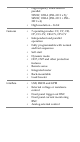
• • Features • • • • • • • • • • Interface • • • • • High capacity when used in parallel: 5250W, 1050A (PEL-3111 x 5)/ 9450W, 1890A (PEL-3111 + PEL3211 x 4) High resolution – 16 bit 7 operating modes: CC, CV, CR, CP, CC+CV, CR+CV, CP+CV Independent and parallel operation Fully programmable with normal and fast sequences Soft start Dynamic mode OCP, OVP and other protection features Remote sense Integrated meter Rack-mountable Load booster USB, RS232 and GPIB External voltage or resistance control Front
Package Contents and Accessories Standard Accessories Item User /Programming Manual CD Quick Start Guide (this document) Load input terminal Cover Terminal fittings: 2 sets of bolts/nuts/springs/washers (type: M8) Power Cord x1 Part Number 82EL-31110EA1 82EL-31110MA1 PEL-011 PEL-012 Region Dependent Optional Accessories Item Rack mount bracket for booster PEL-3211/EIA Rack mount bracket for booster PEL-3211/JIS Rack mount frame for PEL-3021, PEL-3041, PEL-3111/EIA Rack mount frame for PEL-3021, PEL-3041,
Front Panel PEL-3021 and PEL-3041 1 2 4 3 5 6 Local Main File FUNC 7 Utility Help Short P7 Preset Shift 175W 1.5 - 150V 0 - 35A P8 8 9 P5 P6 4 5 6 P1 P2 P3 1 2 P0 CAL. 0 I MON OUT 8 Load On/ Off P9 7 P4 9 3 Lock Clear Enter TRIG OUT 10 14 13 11 12 PEL-3111 Local Main File FUNC Utility Help Short P7 Preset 7 P4 Shift 4 P1 1050W 1.5 - 150V 0 - 70A I MON OUT TRIG OUT P8 8 P5 5 P2 1 2 P0 CAL.
Description 1. Air inlet 2. LCD Display 3. Function keys 4. Power key 5. Main/Local key 6. FUNC/File key 7. Help/Utility key 8. Short key 9. Load On/Off 10. Scroll wheel 11. Number pad, 12. USB port, Preset and Clear/Lock and Enter Shift keys keys 13. I MON OUT, TRIG OUT 14. Input terminals Rear Panel PEL-3021 and PEL-3041 1 2 3 FRAME CONT SER. NO. LB J1 J2 WARNING TO AVOID ELECTRIC SHOCK THE POWER CORD PROTECTIVE GROUNDING CONDUCTOR MUST BE CONNECTED TO GROUND.
PEL-3111 Local Main File FUNC Utility Help Short P7 Preset 7 P4 Shift 4 P1 1050W 1.5 - 150V 0 - 70A I MON OUT TRIG OUT P8 8 P5 5 P2 1 2 P0 CAL. 0 P9 Load On/ Off 9 P6 6 P3 3 Lock Clear Enter PEL-3211 Description 1. Frame control ports, J1, J2 2. Remote sense inputs 3. Rear panel inputs 4. Exhaust fan 5. Power socket and switch 6. GPIB (optional) 7. USB device port 8. USB port 9.
Display Overview 1 2 RS232 LOAD 03/Sep/2012 5 0.00 w 0.000 V 0.000 A 6 CC A Value 0.000 A CC B Value 0.000 A SlewRate 2500.00 mA/us Mode CV I Range H 35A V Range L 15V Function Static Fine 3 A Value Configure 4 Description 1. Date and time 2. Main frame status panel 3. Operation status panel 4. Soft keys 5. Setting area 6.
Power Up 1. Insert the AC power cord into the power socket. 2. Turn the power switch on from the rear panel. (O → —) 3. If the unit doesn’t turn on, press the ON/STBY key on the front panel. 4. The ON/STBY key will go from standby (red) to ON (green). The unit will show the splash screen and then load the settings from when the unit was last powered down. Load Default Settings When first using the PEL-3000, recall the factory default settings to ensure the unit is in a known state.
Setting the Date and Time The date and time settings are used to time-stamp files when saving files. Utility 1. Press Shift + Help > Time Set[F4] to set the date and time. Settings: Month, Day, Year, Hour, Minute Updating the Firmware The PEL-3000 allows the firmware to be updated by end-users. Before using the PEL-3000, please check the GW Instek website or ask your local distributor for the latest firmware. Before updating the firmware, please check the firmware version.
Firmware update File 1. Press 2. Select USB with the Media [F1] soft-key. 3. Press the File Utility [F5] soft-key. 4. Select the *.UPG upgrade file and press Select[F1] twice. Once to select the file and once to confirm. 5. Wait for the update to complete and reset the power. Shift + . FUNC Do not turn the load generator off or remove the USB memory when the firmware is being read or upgraded. Warning Conventions The following conventions are used throughout the user manual.
Select Sub Menu Configure Pressing this type of soft-menu key will enter a submenu. Toggle Parameter or State Function/Item Parameter or State Mode CC This type of soft-menu icon has the function/item on the top of the label and the selected setting or mode on the bottom of the label. Repeatedly press the associated function key (F1~F5) to cycle through each setting. For some parameters, a popup window will also appear. Selection of the setting is the same.
RS232 LOAD 03/Sep/2012 0.000 V 0.00 w 0.000 ACursor Level1 Level2 Timer1 Mode CP 2. Scroll bar 0.00 W 0.00 W 0.025 ms I Range H 35A V Range L 15V Press the Fine Function Dynamic Configure key to select the Enter parameter. 3. Then use the number pad* or scroll wheel** to edit the parameter value. RS232 LOAD 03/Sep/2012 0.00 w 0.000 V 0.000 A Parameter CC A Value 0.000 A CC B Value 1.000 A SlewRate 2500.
that allows you to edit parameters one digit value at a time using the scroll wheel. This is called Cursor mode. Please see the user manual for more information. Entering Alphanumeric Characters When renaming files, creating memos or notes, you will be required to enter alphanumeric characters when the character entry screen appears. 1. Only alphanumeric characters as well as space [ ], underscore [_] and minus [-] characters are allowed.
SPECIFICATIONS The following are the basic specifications for the PEL3000 series. For detailed specifications, please see the user manual Rating Model Operating Voltage Current Power PEL-3021 PEL-3041 PEL-3111 1.5V~150V 35A 175W 1.5V~150V 70A 350W 1.5V~150V 210A 1050W CC Mode Operating Range Model PEL-3021 H Range 0A~35A M Range 0A~3.5A L Range 0A~0.35A PEL-3041 0A~70A 0A~7A 0A~0.7A PEL-3111 0A~210A 0A~21A 0A~2.1A CR Mode Operating Range Model PEL-3021 H Range 23.3336S ~400uS (42.857mΩ ~2.
CV Mode Operating Range Model PEL-3021 PEL-3041 H Range 1.5V~150V 1.5V~150V M Range 1.5V~15V 1.5V~15V PEL-3111 1.5V~150V 1.5V~15V CP Mode Operating Range Model PEL-3021 PEL-3041 H Range 17.5W ~175W 35W~350W M Range 1.75W ~17.5W 3.5W~35W L Range 0.175W~1.75W 0.35W~3.5W PEL-3111 105W ~1050W 10.5W ~105W 1.05W ~10.5W Slew Rate CC Mode Setting Range Model PEL-3021 PEL-3041 H Range 2.5mA/us 5mA/us ~2.
EC Declaration of Conformity We GOOD WILL INSTRUMENT CO., LTD. No.7-1, Jhongsing Rd., Tucheng Dist., New Taipei City 236, Taiwan GOOD WILL INSTRUMENT (SUZHOU) CO., LTD. No.