Programmable DC Power Supply PSU Series PROGRAMMING MANUAL Revision 1.
This manual contains proprietary information, which is protected by copyright. All rights are reserved. No part of this manual may be photocopied, reproduced or translated to another language without prior written consent of Good Will company. The information in this manual was correct at the time of printing. However, Good Will continues to improve products and reserves the rights to change specification, equipment, and maintenance procedures at any time without notice. Good Will Instrument Co., Ltd. No.
Table of Contents Table of Contents SAFETY INSTRUCTIONS ................................................... 4 GETTING STARTED ........................................................... 8 PSU Series Overview .............................. 9 Appearance .......................................... 13 Configuration Settings ......................... 21 REMOTE CONTROL ........................................................ 30 Interface Configuration ........................ 31 Command Syntax ...................
PSU Programming Manual SAFETY INSTRUCTIONS This chapter contains important safety instructions that you must follow during operation and storage. Read the following before any operation to insure your safety and to keep the instrument in the best possible condition. Safety Symbols These safety symbols may appear in this manual or on the instrument. WARNING Warning: Identifies conditions or practices that could result in injury or loss of life.
SAFETY INSTRUCTIONS Do not dispose electronic equipment as unsorted municipal waste. Please use a separate collection facility or contact the supplier from which this instrument was purchased. Safety Guidelines General Guideline CAUTION Do not place any heavy object on the PSU. Avoid severe impact or rough handling that leads to damaging the PSU. Do not discharge static electricity to the PSU. Use only mating connectors, not bare wires, for the terminals.
PSU Programming Manual Cleaning the PSU Operation Environment Disconnect the power cord before cleaning. Use a soft cloth dampened in a solution of mild detergent and water. Do not spray any liquid. Do not use chemicals containing harsh material such as benzene, toluene, xylene, and acetone.
SAFETY INSTRUCTIONS Power cord for the United Kingdom When using the power supply in the United Kingdom, make sure the power cord meets the following safety instructions.
PSU Programming Manual GETTING STARTED This chapter describes the power supply in a nutshell, including its main features and front / rear panel introduction. After going through the overview, please read the theory of operation to become familiar with the operating modes, protection modes and other safety considerations. GETTING STARTED ........................................................... 8 PSU Series Overview ......................................................... 9 Series lineup ..............
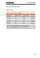
GETTING STARTED PSU Series Overview Series lineup The PSU series consists of 5 models, covering a number of different current, voltage and power capacities: Model name Voltage Rating1 Current Rating2 Power PSU 6-200 6V 200A 1200W PSU 12.5-120 12.5V 120A 1500W PSU 20-76 20V 76A 1520W PSU 40-38 40V 38A 1520W PSU 60-25 60V 25A 1500W 1Minimum voltage guaranteed to 0.2% of rating voltage. 2Minimum current guaranteed to 0.4% of rating current.
PSU Programming Manual Main Features Performance Features Interface 10 High power density: 1500W in 1U Universal input voltage 85~265Vac, continuous operation. Output voltage up to 60V, current up to 200A. Active power factor correction. Parallel master/slave operation with active current sharing. Remote sensing to compensate for voltage drop in load leads. 19" rack mounted ATE applications.
GETTING STARTED Accessories Before using the PSU power supply unit, check the package contents to make sure all the standard accessories are included. Standard Part number Accessories Description Qty.
PSU Programming Manual Optional Part number Accessories Download Other Description PSU-01C Cable for 2 units of PSU-Series in parallel mode connection PSU-01B Bus Bar for 2 units of PSU-Series in parallel mode connection PSU-02C Cable for 3 units of PSU-Series in parallel mode connection PSU-02B Bus Bar for 3 units of PSU-Series in parallel mode connection PSU-03C Cable for 4 units of PSU-Series in parallel mode connection PSU-03B Bus Bar for 4 units of PSU-Series in parallel mode connection
GETTING STARTED Appearance PSU Series Front Panel 1 2 3 4 PSU 40-38 5 Display Area Voltage DC Power Supply Current CV CC 0 - 40 V / 0 - 38A V A VOLTAGE VSR LAN RMT CURRENT ERR DLY ALM ISR Lock/ Local PROT Function Test Set Unlock ALM_CLR M1 M2 M3 M1 M2 Shift M3 RUN Output : Long Push 6 7 8 9 10 11 12 13 1. Power Switch Used to turn the power on/off. 2. USB A Port USB A port for data transfer, loading test scripts etc. 3.
PSU Programming Manual 6. Lock/Local Button Lock/Local Unlock (Long push) Used to unlock the front panel buttons. Unlock Button 7. PROT Button Used to lock all front panel buttons other than the Output Button or it switches to local mode. PROT Used to set and display OVP, OCP and UVL. ALM_CLR (Long push) Used to release protection functions that have been activated. ALM_CLR Button 8. Function Button Function Used to configure the various function. M1 (+Shift) Used to recall the M1 setup.
GETTING STARTED 11. Shift Button 12. Output Button 13. Output ON LED Shift Output Used to enable the functions that are written in blue characters below the button. Used to turn output on and off. Lights in green during output ON.
PSU Programming Manual PSU Series Display and Operation Panel Display Area 14 16 15 17 CV CC V A VOLTAGE VSR 18 LAN 19 CURRENT RMT 20 ERR 21 DLY 22 ALM 23 ISR 24 M1 25 M2 26 M3 27 RUN 28 14. Voltage Meter Displays the voltage or the parameter number of a Function parameter. 15. Current Meter Displays the current or the value of a Function parameter. 16. CV LED Lights in green during constant voltage mode. 17. CC LED Lights in green during constant current mode. 18.
GETTING STARTED 24. ISR LED The current slew rate enable. 25. M1 LED Lights in green when the memory value are being recalled or saved. 26. M2 LED Lights in green when the memory value are being recalled or saved. 27. M3 LED Lights in green when the memory value are being recalled or saved. 28. RUN LED Auto sequence has been activated. Note Only the ERR and ALM LED’s are red. All the others are green.
PSU Programming Manual Rear Panel 1 2 ISOLATED PROGRAMMING 4 - 20mA 3 4 5 6 7 8 1 2 ISOLATED PROGRAMMING 0 - 5V / 0 - 10V 3 4 5 6 7 8 9 10 DC OUTPUT ANALOG PROGRAMMING S LS NC REMOTE SENSE 8 1. RS 485 / 232 L N LAN LS S OUT 7 AC Input IN AC INPUT 6 5 L 4 3 2 1 Wire clamp connector. N AC INPUT 2. DC Output 3. USB 4. LAN 18 Output terminals for 6V to 60V models. USB port for controlling the PSU remotely. RS 485 / 232 LAN Ethernet port for controlling the PSU remotely.
GETTING STARTED 5. RS 485 / 232 Remote-IN LAN Two different types of cables can be used for RS232 or RS485-based remote control. PSU-232: RS232 cable with DB9 connector kit. PSU-485: RS485 with DB9 connector kit. 6. RS 485 / 232 Remote-OUT LAN RJ-45 connector that is used to daisy chain power supplies with the Remote-IN port to form a communication bus. PSU-485S: Serial link cable with RJ-45 shielded connector. 7. Analog Control 8.
PSU Programming Manual DC OUTPUT RS 485 / 232 OUT L N LAN IN AC INPUT 20
GETTING STARTED Configuration Settings Setting Normal Function Settings The normal function settings (F-01~F-61, F70~F-76) and F-88 ~ F-89 can be easily configured with the Function key. Ensure the load is not connected. Ensure the output is off. Function settings F-90~97 can only be viewed. Note Function setting F-89 (Show Version) can only be viewed, not edited. Configuration settings F-90~ F-97 cannot be edited in the Normal Function Settings. Use the Power On Configuration Settings.
PSU Programming Manual 4. Use the current knob to set the parameter for the chosen F setting. Press the Voltage knob to save the configuration setting. ConF will be displayed when it is configuring. CV Exit 22 LAN RMT Voltage CC V A VOLTAGE VSR Current CURRENT ERR DLY ALM ISR M1 M2 M3 RUN Press the Function key again to exit the configuration settings. The function key light will turn off.
GETTING STARTED Setting Power On Configuration Settings Background The Power On configuration settings can only be changed during power up to prevent the configuration settings being inadvertently changed. Ensure the load is not connected. Ensure the power supply is off. Steps 1. Hold the Function key whilst turning the power on.
PSU Programming Manual Press the Voltage knob to save the configuration setting. ConF will be displayed when it is configuring. CV CC V A VOLTAGE VSR Exit 24 LAN RMT CURRENT ERR DLY ALM ISR M1 M2 M3 RUN Cycle the power to save and exit the configuration settings.
GETTING STARTED Configuration Table Please use the configuration settings listed below when applying the configuration settings. Normal Function Settings Output ON delay time Output OFF delay time Setting F-01 F-02 V-I mode slew rate select F-03 Setting Range 0.00s~99.99s 0.00s~99.99s 0 = CV high speed priority (CVHS) 1 = CC high speed priority (CCHS) 2 = CV slew rate priority (CVLS) 3 = CC slew rate priority (CVLS) F-04 0.001~0.06V/msec (PSU 6-200) 0.001~0.125V/msec (PSU 12.5-120) 0.001~0.
PSU Programming Manual Internal resistance setting Bleeder circuit control Buzzer ON/OFF control OCP Delay Time Current Setting Limit (I-Limit) Voltage Setting Limit (V-Limit) Display memory parameter when recalling (M1, M2, M3) F-09 F-10 F-12 0~0.03Ω (PSU 6-200) 0~0.104Ω (PSU 12.5-120) 0~0.263Ω (PSU 20-76) 0~1.053Ω (PSU 40-38) 0~2.4Ω (PSU 60-25) 0 = OFF, 1 = ON 0 = OFF, 1 = ON 0.1 ~ 2.
GETTING STARTED Show MAC Address-2 Show MAC Address-3 Show MAC Address-4 Show MAC Address-5 Show MAC Address-6 LAN Enable DHCP IP Address-1 IP Address-2 IP Address-3 IP Address-4 Subnet Mask-1 Subnet Mask-2 Subnet Mask-3 Subnet Mask-4 Gateway-1 Gateway-2 Gateway-3 Gateway-4 DNS address -1 DNS address -2 DNS address-3 DNS address-4 Socket Server Enable/Disable Web Server Enable/Disable Web Password Enable/Disable Web Enter Password UART Settings F-31 F-32 F-33 F-34 F-35 F-36 F-37 F-39 F-40 F-41 F-42 F-43 F-
PSU Programming Manual UART Address (For TDK) F-76 System Settings Factory Set Value F-88 Show Version F-89 00 ~ 31 0 = None 1 = Return to factory default settings 0, 1 = Version 2, 3, 4, 5 = Build date (YYYYMMDD) 6, 7 = Keyboard CPLD 8, 9 = Analog Board CPLD A, B = Analog Board FPGA C, D, E, F = Kernel Build (YYYYMMDD) G, H = Test Command Version I, J, K, L = Test Command Build (YYYYMMDD) Power On Configuration Settings* CV Control F-90 CC Control F-91 Output Status when Power ON F-92 Master/Sl
GETTING STARTED Control Range F-97 External Output Control F-98 Function Special Function Settings* Calibration F-00 *Note 0 = 5V [5kΩ], 1 = 10V [10kΩ] 0 = OFF, 1 = ON 0000 ~ 9999 Power On configuration settings can only be set during power up. They can, however, be viewed under normal operation.
PSU Programming Manual REMOTE CONTROL This chapter describes basic configuration of IEEE488.2 based remote control. Interface Configuration ................................................... 31 Command Syntax ............................................................ 55 Command List ................................................................. 58 Status Register Overview ................................................ 103 Error List .................................................................
REMOTE CONTROL Interface Configuration USB Remote Interface Configuration USB Configuration Steps PC side connector Type A, host PSU side connector Rear panel Type B, slave Speed 1.1/2.0 (full speed/high speed) USB Class CDC (communications device class) 1. Connect the USB cable to the rear panel USB B port. 2. Change the Rear panel-USB (F-22) Page 21 setting to 2 (Auto Detect Speed) or 1 (USB Full Speed). Note If you are not using the rear panel USB device port, set F-22 to 0 (Disable USB).
PSU Programming Manual Function Check Functionality check Invoke a terminal application such as Realterm. To check the COM port No., see the Device Manager in the PC. For WinXP; Control panel → System → Hardware tab. Run this query command via the terminal application after the instrument has been configured for USB remote control (page 31). *idn? This should return the Manufacturer, Model number, Serial number, and Firmware version in the following format. GW-INSTEK,PSU40-38,TW123456,T0.01.
REMOTE CONTROL GPIB Remote Interface Configuration To use GPIB, the optional GPIB option (GW Instek part number: PSU-GPIB) must be installed. This is a factory installed option and cannot be installed by the end-user. Only one GPIB address can be used at a time. Configure GPIB 1. Ensure the PSU is off before proceeding. 2. Connect a GPIB cable from a GPIB controller to the GPIB port on the PSU. 3. Turn the PSU on. 4. Press the Function key to enter the Page 21 Normal configuration settings. 5.
PSU Programming Manual 7. The RMT indicator will turn on when a remote connection has been established.
REMOTE CONTROL Functionality check 1. Start the NI Measurement and Automation Explorer (MAX) program. Using Windows, press: Start>All Programs>National Instruments>Measurement & Automation 2. From the Configuration panel access; My System>Devices and Interfaces>GPIB 3. Press Scan for Instruments.
PSU Programming Manual 4. Select the device (GPIB address of PSU) that now appears in the System>Devices and Interfaces > GPIB-USB-HS “GPIBX” node. 5. Click on the VISA Properties tab on the bottom. 6. Click Open Visa Test Panel. 6 4 5 7. Click on Configuration. 8. Click on the GPIB Settings tab and confirm that the GPIB settings are correct. 7 8 9. Click on the I/O Settings tab. 10.
REMOTE CONTROL check box is checked, and the terminal character is \n (Value: xA). 11. Click Apply Changes. 9 10 11 12. Click on Input/Output. 13. Click on the Basic/IO tab. 14. Enter *IDN? in the Select or Enter Command drop down box. 15. Click Query. 16. The *IDN? query will return the Manufacturer, model name, serial number and firmware version in the dialog box. GW-INSTEK,PSU40-38, TW123456,T0.02.
PSU Programming Manual 12 13 14 15 16 UART Remote Interface Configure UART The PSU uses the IN & OUT ports for UART communication coupled with RS232 (GW Part number PSU-232) or RS485 adapters (GW part number PSU-485) Overview The pin outs for the adapters are shown below. PSU-232 RS232 cable with DB9 connector 38 DB-9 Connector Remote IN Port Pin No. Pin No.
REMOTE CONTROL PSU-485 RS485 cable with DB9 connector Steps DB-9 Connector Remote IN Port Pin No. Pin No. Name Remarks Name Housing Shield Housing Shield 9 TXD - 6 RXD - 8 TXD + 3 RXD + 1 SG 1 SG 5 RXD - 5 TXD - 4 RXD + 4 TXD + 1. Connect the RS232 serial cable (included in the PSU-232 kit) or RS485 serial cable (included in the PSU-485 kit) to the (Remote IN port) on the rear panel. Twisted pair Twisted pair RS 485 / 232 Connect the other end of the cable to the PC. 2.
PSU Programming Manual UART address if TDK is selected for F-75. F-76 = 00~31 3. The RMT indicator will turn on when a remote connection has been established. CV CC V A VOLTAGE VSR LAN RMT CURRENT ERR DLY ALM ISR M1 M2 M3 RUN RMT indicator Note 40 If TDK (emulation mode) is selected for F-75, the TDK GENESYS legacy commands should be used for remote commands. See the TDK Genesys user manual for details.
REMOTE CONTROL UART Function Check Functionality check Invoke a terminal application such as Realterm. To check the COM port No, see the Device Manager in the PC. For WinXP; Control panel → System → Hardware tab. Run this query command via the terminal application after the instrument has been configured for either RS232 or RS485 remote control (page 38). *idn? This should return the Manufacturer, Model number, Serial number, and Firmware version in the following format: GW-INSTEK,PSU40-38,,T0.01.
PSU Programming Manual Multiple Unit Connection Using Local RS485 Bus The PSU power supplies can have up to 31 units daisy-chained together using the 8 pin connectors (IN OUT ports) on the rear panel. The first unit in the chain is remotely connected to a PC using RS232 or RS485. Each subsequent unit is daisy-chained to the next using an RS485 local bus. The OUT port on the last terminal must be terminated by the end terminal connector.
REMOTE CONTROL 4. Terminate the OUT port of the last unit with the end terminal connector included in the PSU-232 or PSU-485 connection kit. 5. Press the Function key to enter the Page 21 Normal configuration settings for the master unit. Set the following settings: Configure the master unit as you F-70 = 1 or 2 normally would for RS232 or RS485 remote control. Set the baud rate (set all units F-71 = 0~7 the same). F-72 = 1 Set to 8 data bits. F-73 = 0 Parity to none. F-74 = 1 1 Stop bit.
PSU Programming Manual F-76 = 00~31 Set the address of each slave to a unique address identifier 7. Multiple units can now be operated at the same time, see the function check below for usage details. Serial link cable with RJ-45 shielded connectors from PSU-232 or PSU485 connection kit 8 Pin Connector (IN) 8 Pin Connector (OUT) Pin No. Name Pin No.
REMOTE CONTROL Run this query command via the terminal application after the instruments have been configured for multi-unit control. See page 42. ADR 8 IDN? The identity string for the Master unit will be returned: GW-INSTEK,PSU40-38,,T0.01.12345678 Type the following: ADR 11 IDN? The identity string for the slave with address 11 will be returned: GW-INSTEK,PSU40-38,,T0.01.12345678 Note: TDK commands do not use LF (line feed) codes to terminate commands.
PSU Programming Manual Configure Ethernet Connection The Ethernet interface can be configured for a number of different applications. Ethernet can be configured for basic remote control or monitoring using a web server or it can be configured as a socket server. The PSU series supports both DHCP connections so the instrument can be automatically connected to an existing network or alternatively, network settings can be manually configured.
REMOTE CONTROL 2. Press the Function key to enter the Page 21 Normal configuration settings. Set the following LAN settings: F-36 = 1 Turn LAN on F-37 = 1 Enable DHCP F-59 = 1 Turn the web server on F-60 = 0 or 1 Set to 0 to disable web password, set to 1 to enable web password F-61 = 0000 Set the web password ~9999 3. The LAN indicator will turn on when a network cable is plugged in.
PSU Programming Manual F-41 = CCC F-42 = DDD IP Address part 3 of 4 IP Address part 4 of 4 http:// AAA.BBB.CCC.DDD The web browser interface appears.
REMOTE CONTROL Sockets Server Configuration Configuration This configuration example will configure the PSU socket server. The following configuration settings will manually assign the PSU an IP address and enable the socket server. The socket server port number is fixed at 2268. 1. Connect an Ethernet cable from the network to the rear panel Ethernet port. LAN 2. Press the Function key to enter the Page 21 Normal configuration settings.
PSU Programming Manual Socket Server Function Check Background To test the socket server functionality, National Instruments Measurement and Automation Explorer can be used. This program is available on the NI website, www.ni.com., via a search for the VISA Run-time Engine page, or “downloads” at the following URL, http://www.ni.com/visa/ Requirements Operating System: Windows XP, 7, 8 Functionality check 1. Start the NI Measurement and Automation Explorer (MAX) program.
REMOTE CONTROL 3 2 4. Select Manual Entry of Raw Socket from the popup window. 4 5. Enter the IP address and the port number of the PSU. The port number is fixed at 2268. 6. Click the Validate button. 7. A popup will appear if a connection is successfully established. 8. Click Next.
PSU Programming Manual 7 5 6 8 9. Next configure the Alias (name) of the PSU connection. In this example the Alias is: PSU_DC1 10. Click finish. 9 10 11. The IP address of the PSU will now appear under Network Devices in the configuration panel. Select this icon now. 12. Click Open VISA Test Panel.
REMOTE CONTROL 12 11 13. Click the Configuration icon, 14. Click on I/O Settings. 15. Make sure the Enable Termination Character check box is checked, and the terminal character is \n (Value: xA). 16. Click Apply Changes. 13 14 15 16 17. Click the Input/Output icon. 18. Enter *IDN? in the Select or Enter Command dialog box if it is not already. 19. Click the Query button.
PSU Programming Manual 20. The *IDN? query will return the Manufacturer, model name, serial number and firmware version in the dialog box. GW-INSTEK,PSU40-38,TW123456,T0.02.
REMOTE CONTROL Command Syntax Compatible Standard Command Structure IEEE488.2 Partial compatibility SCPI, 1999 Partial compatibility SCPI commands follow a tree-like structure, organized into nodes. Each level of the command tree is a node. Each keyword in a SCPI command represents each node in the command tree. Each keyword (node) of a SCPI command is separated by a colon (:). For example, the diagram below shows an SCPI sub-structure and a command example.
PSU Programming Manual Query A query is a simple or compound command followed by a question mark (?). A parameter (data) is returned. Example meas:curr:dc? Compound Two or more commands on the same command line. Compound commands are separated with either a semicolon (;) or a semi-colon and a colon (;:). A semi-colon is used to join two related commands, with the caveat that the last command must begin at the last node of the first command.
REMOTE CONTROL Command Forms Commands and queries have two different forms, long and short. The command syntax is written with the short form of the command in capitals and the remainder (long form) in lower case. The commands can be written in capitals or lower-case, just so long as the short or long forms are complete. An incomplete command will not be recognized. Below are examples of correctly written commands.
PSU Programming Manual integers 0, 1, 2, 3 decimal numbers 0.1, 3.14, 8.5 floating point 4.5e-1, 8.25e+1 any of NR1, 2, 3 1, 1.5, 4.5e-1 Definitive length arbitrary block data. A single decimal digit followed by data. The decimal digit specifies how many 8-bit data bytes follow. Message Terminator LF Line feed code Command List Display Commands :DISPlay:MENU[:NAME] ................................................... 62 :DISPlay[:WINDow]:TEXT:CLEar ........
REMOTE CONTROL Output Commands :OUTPut:DELay:ON............................................................ 68 :OUTPut:EXTernal:LOGic ................................................. 68 :OUTPut:EXTernal[:STATe] ............................................... 69 :OUTPut:DELay:OFF .......................................................... 69 :OUTPut:MODE................................................................... 69 :OUTPut:PON[:STATe] .......................................................
PSU Programming Manual [:AMPLitude] .......................................................................... 83 [:SOURce]:VOLTage[0]:LIMit:AUTO ............................... 84 [:SOURce]:VOLTage[0]:LIMit:LOW ................................. 84 [:SOURce]:VOLTage[0]:PROTection[:LEVel] ................. 85 [:SOURce]:VOLTage[0]:PROTection:TRIPped ............... 85 [:SOURce]:VOLTage[0]:SLEW:RISing .............................. 86 [:SOURce]:VOLTage[0]:SLEW:FALLing ..........................
REMOTE CONTROL :SYSTem:PREset ................................................................... 99 :SYSTem:VERSion ................................................................ 99 :SYSTem:REBoot ................................................................ 100 Common Commands *CLS ...................................................................................... 100 *ESE ...................................................................................... 100 *ESR .............................
PSU Programming Manual Display Commands :DISPlay:MENU[:NAME] ................................................... 62 :DISPlay[:WINDow]:TEXT:CLEar.................................... 62 :DISPlay[:WINDow]:TEXT[:DATA]................................. 63 :DISPlay:BLINk ..................................................................... 63 Set :DISPlay:MENU[:NAME] Query Description The DISPlay MENU command selects a screen menu or queries the current screen menu.
REMOTE CONTROL Set :DISPlay[:WINDow]:TEXT[:DATA] Query Description Sets or queries the data text that will be written to the display. Writing to the display will overwrite data that is currently on the screen. Overwriting a display area with a shorter string may or may not overwrite the screen. The string must be enclosed in quotes: “STRING”. Only ASCII characters 20H to 7EH can be used in the .
PSU Programming Manual Initiate Commands :INITiate:CONTinuous[:TRANsient] ................................ 64 :INITiate[:IMMediate]:NAME ............................................ 64 :INITiate[:IMMediate][:TRANsient] ................................... 65 Set :INITiate:CONTinuous[:TRANsient] Query Description This command continuously initiates software triggers for the transient or output triggers.
REMOTE CONTROL :INITiate[:IMMediate][:TRANsient] Set Description This command controls the enabling of output triggers. When a trigger is enabled, a trigger causes the specified action to occur. If the trigger system is not enabled, all triggers are ignored.
PSU Programming Manual Measure Commands :MEASure[:SCALar]:ALL[:DC] ........................................... 66 :MEASure[:SCALar]:CURRent[:DC] .................................. 66 :MEASure[:SCALar]:VOLTage[:DC] ................................. 66 :MEASure[:SCALar]:POWer[:DC]......................................
REMOTE CONTROL :MEASure[:SCALar]:POWer[:DC] Query Description Takes a measurement and returns the average output power. Syntax Return :MEASure[:SCALar]:POWer[:DC]? Returns the power measured in watts. "+0.
PSU Programming Manual Output Commands :OUTPut:DELay:ON ........................................................... 68 :OUTPut:EXTernal:LOGic ................................................. 68 :OUTPut:EXTernal[:STATe] ............................................... 69 :OUTPut:DELay:OFF .......................................................... 69 :OUTPut:MODE .................................................................. 69 :OUTPut:PON[:STATe].......................................................
REMOTE CONTROL Set :OUTPut:EXTernal[:STATe] Query Description Sets whether the output will be turned on or off externally. By default this setting is turned off. Syntax :OUTPut:EXTernal[:STATe] {|OFF|ON} Return Syntax :OUTPut:EXTernal[:STATe]? ON | 1 External control is performed. OFF | 0 External control is not performed. Parameter Return parameter Returns output status of the instrument.
PSU Programming Manual Set :OUTPut:PON[:STATe] Query Description Sets the output state at power-on. This is the equivalent to the F-92 (Output Status when Power ON) power on configuration settings. These settings only apply after the unit has been reset. Syntax :OUTPut:PON[:STATe] {|SAFE|FORCe |AUTO} Return Syntax Parameter :OUTPut:PON[:STATe]? SAFE | 0 The PSU turns on in the same state the unit was in prior to the previous shut down. The output is set to off (default).
REMOTE CONTROL Set :OUTPut[:STATe]:TRIGgered Query Description Turns the output on or off when a software trigger is generated. Syntax :OUTPut[:STATe]:TRIGgered { |OFF|ON } Query Syntax Parameter :OUTPut[:STATe]:TRIGgered? OFF | 0 Turns the output off when a software trigger ON | 1 Return parameter is generated (*TRG). Turns the output on when a software trigger is generated (*TRG). Returns output trigger status of the instrument.
PSU Programming Manual Status Commands For an overview of all the status registers, their associated register contents and the system diagram, please see the status overview on page 103 :STATus:OPERation[:EVENt] ........................................... 72 :STATus:OPERation:CONDition ...................................... 72 :STATus:OPERation:ENABle ............................................ 73 :STATus:OPERation:PTRansition ...................................... 73 :STATus:OPERation:NTRansition .......
REMOTE CONTROL Set :STATus:OPERation:ENABle Query Description Sets or queries the bit sum of the Operation Status Enable register. Syntax :STATus:OPERation:ENABle Query Syntax :STATus:OPERation:ENABle? Parameter 0~32767 Return parameter 0~32767 Set :STATus:OPERation:PTRansition Query Description Sets or queries the bit sum of the positive transition filter of the Operation Status register.
PSU Programming Manual :STATus:QUEStionable:CONDition Description Query Queries the status (bit sum) of the Questionable Status register. This query will not clear the register. Query Syntax :STATus:QUEStionable:CONDition? Return parameter 0~32767 Set :STATus:QUEStionable:ENABle Query Description Sets or queries the bit sum of the Questionable Status Enable register.
REMOTE CONTROL Parameter Return parameter 0~32767 0~32767 :STATus:PRESet Description Set This command resets the ENABle register, the PTRansistion filter and NTRansistion filter on the Operation Status and Questionable Status Registers. The registers/filters will be reset to a default value.
PSU Programming Manual Source Commands [:SOURce]:CURRent:EXTernal:RANGe........................... 76 [:SOURce]:CURRent:EXTernal:SOURce .......................... 77 [:SOURce]:CURRent[:LEVel][:IMMediate] [:AMPLitude].......................................................................... 77 [:SOURce]:CURRent[:LEVel]:TRIGgered[:AMPLitude]. 78 [:SOURce]:CURRent:LIMit:AUTO .................................... 78 [:SOURce]:CURRent:PROTection:DELay ........................
REMOTE CONTROL Example CURR:EXT:RANG? LOW Returns LOW range. Set [:SOURce]:CURRent:EXTernal:SOURce Query Description Sets whether constant current will be controlled externally or not. Note: the setting will only be valid after the power has been cycled. Syntax [:SOURce]:CURRent:EXTernal:SOURce {NONE|VOLTage} Query Syntax [:SOURce]:CURRent:EXTernal:SOURce? Parameter/Return NONE External control is not used. parameter VOLTage External control is used.
PSU Programming Manual [:SOURce]:CURRent[:LEVel]:TRIGgered [:AMPLitude] Set Query Description Sets or queries the current level in amps when a software trigger has been generated. Syntax [:SOURce]:CURRent[:LEVel]:TRIGgered[:AMPLitude] { (A)| MINimum|MAXimum} Query Syntax Parameter [:SOURce]:CURRent[:LEVel]:TRIGgered[:AMPLitude]? 0%~105% of the rated current output in amps. Minimum current level. MIN Maximum current level. MAX Return Parameter Returns the current level.
REMOTE CONTROL Query Syntax Parameter [:SOURce]:CURRent:PROTection:DELay? 0.1~2.0 seconds, where 0=no delay The maximum allowed delay time MAX The minimum allowed delay time MIN Return parameter Returns the delay time in seconds Example SOUR:CURR:PROT:DEL MAX Sets the current protection delay to the maximum. Set [:SOURce]:CURRent:PROTection[:LEVel] Query Description Sets or queries the OCP (over-current protection) level in amps.
PSU Programming Manual Parameter OFF | 0 ON | 1 Return parameter Example Turns the OCP off. Turns the OCP on. Returns the over current protection state in format. SOUR:CURR:PROT:STAT OFF Turns OCP off. Set [:SOURce]:CURRent:PROTection:TRIPped Query Description Returns the state of the current protection circuits. Query Syntax [:SOURce]:CURRent:PROTection:TRIPped? Return parameter Example Returns protection status.
REMOTE CONTROL Set [:SOURce]:CURRent:SLEW:FALLing Query Description Sets or queries the falling current slew rate. This is only applicable for CC slew rate priority mode.
PSU Programming Manual Syntax [:SOURce]:RESistance[:LEVel][:IMMediate][:AMPLitude ] {(OHM)|MINimum|MAXimum} Query Syntax [:SOURce]:RESistance[:LEVel][:IMMediate][:AMPLitude ]? Resistance in ohms: Parameter MIN MAX Return parameter Example 0 ohm ~ Rrated = Vrated/Irated Minimum internal resistance in ohms Maximum internal resistance in ohms Returns the internal resistance in ohms. SOUR:RES:LEV:IMM:AMPL 0.1 Sets the internal resistance to 100mΩ.
REMOTE CONTROL Example VOLT:EXT:SOUR? NONE External control is not used. [:SOURce]:VOLTage[0][:LEVel][:IMMediate] [:AMPLitude] Set Query Description Sets or queries the voltage level in volts. Syntax [:SOURce]:VOLTage[0][:LEVel][:IMMediate][:AMPLitude ] {(V)|MINimum|MAXimum} Query Syntax [:SOURce]:VOLTage[0][:LEVel][:IMMediate][:AMPLitude ]? Parameter 0~105% of the rated output voltage in volts.
PSU Programming Manual Set [:SOURce]:VOLTage[0]:LIMit:AUTO Description Query Sets whether to limit the voltage setting so that it does not exceed the OVP setting or become lower than the UVP setting. If you enable the limit when the OVP setting is lower than the voltage setting, the OVP setting will be set to 105 % of the voltage setting. If you enable the limit when the UVP setting is higher than the voltage setting, the UVP setting will be set equal to the voltage setting.
REMOTE CONTROL Set [:SOURce]:VOLTage[0]:PROTection[:LEVel] Query Description Sets or queries the overvoltage protection level. Syntax [:SOURce]:VOLTage[0]:PROTection[:LEVel] {(V)|MINimum|MAXimum} Query Syntax [:SOURce]:VOLTage[0]:PROTection[:LEVel]? Parameter/Return Minimum: Depends on the unit type: MIN MAX Example if Vrated * 0.1 > 5V, then Minimum = 5V, else Minimum = Vrated * 0.1 Maximum: Vrated * 1.
PSU Programming Manual Set [:SOURce]:VOLTage[0]:SLEW:RISing Query Description Sets or queries the rising voltage slew rate. This is only applicable for CV slew rate priority mode. Syntax [:SOURce]:VOLTage[0]:SLEW:RISing {(V)|MINimum|MAXimum} Query Syntax [:SOURce]:VOLTage[0]:SLEW:RISing? 0 ~ Vrated/100msec Minimum rising voltage slew rate MIN Maximum rising voltage slew rate MAX Return parameter Returns the slew rate in A/ms.
REMOTE CONTROL System Function Command :SYSTem:CONFigure:BEEPer[:STATe] ............................ 88 :SYSTem:CONFigure:BLEeder[:STATe]........................... 88 :SYSTem:CONFigure:CURRent:CONTrol ....................... 88 :SYSTem:CONFigure:VOLTage:CONTrol ...................... 89 :SYSTem:CONFigure:OUTPut:PON[:STATe] ................ 89 :SYSTem:CONFigure:PROTection:RECovery ................. 90 :SYSTem:CONFigure:MSLave ............................................
PSU Programming Manual Set :SYSTem:CONFigure:BEEPer[:STATe] Query Description Sets or queries the buzzer state on/off. Syntax :SYSTem:CONFigure:BEEPer[:STATe] {|OFF|ON} Query Syntax Parameter :SYSTem:CONFigure:BEEPer[:STATe]? Turns the buzzer off. OFF | 0 Turns the buzzer on. ON | 1 Return parameter Returns the buzzer status. Set :SYSTem:CONFigure:BLEeder[:STATe] Query Description Sets or queries the status of the bleeder resistor.
REMOTE CONTROL 3 External resistance control; 10kΩ = Io min, 0kΩ = Io max. Set :SYSTem:CONFigure:VOLTage:CONTrol Query Description Sets or queries the CV control mode (local control (panel), external voltage control, external resistance control). This setting is applied only after the unit is reset.
PSU Programming Manual Set :SYSTem:CONFigure:PROTection:RECovery Query Description Sets or queries how the OHP, FAN, AC-FAIL, and SD alarms are cleared. Syntax Return Syntax :SYSTem:CONFigure:PROTection:RECovery {SAFE|AUTO} Parameter :SYSTem:CONFigure:PROTection:RECovery? The output is not turned on automatically SAFE AUTO when the cause of the alarm is fixed. The output is turned on automatically when the cause of the alarm is fixed.
REMOTE CONTROL HIGH | 0 Active high LOW | 1 Active low Return Parameter Returns the logic setting. Parameter Set :SYSTem:COMMunicate:ENABle Query Description Enables/Disables GPIB, USB or other remote interfaces such as Sockets and the Web Server. Syntax :SYSTem:COMMunicate:ENABle { |OFF|ON,GPIB|USB|SOCKets|WEB|SERial} Query Syntax :SYSTem:COMMunicate:ENABle? {GPIB|USB|SOCKets|WEB|SERial} Disables the selected interface. OFF | 0 Enables the selected interface.
PSU Programming Manual Example SYST:COMM:GPIB:SELF:ADDR 15 Sets the GPIB address to 15. Set :SYSTem:COMMunicate:LAN:IPADdress Query Description Sets or queries LAN IP address. Note: the setting will only be valid after the power has been cycled. Syntax :SYSTem:COMMunicate:LAN:IPADdress Query Syntax :SYSTem:COMMunicate:LAN:IPADdress? Parameter/Return LAN IP address in string format ( “address”) Applicable ASCII characters: 20H to 7EH Example SYST:COMM:LAN:IPAD “172.16.5.
REMOTE CONTROL Set :SYSTem:COMMunicate:LAN:SMASk Query Description Sets or queries the LAN subnet mask. Note: the setting will only be valid after the power has been cycled. Syntax :SYSTem:COMMunicate:LAN:SMASk Query Syntax :SYSTem:COMMunicate:LAN:SMASk? Parameter/Return Subnet mask in string format ( “mask”) Applicable ASCII characters: 20H to 7EH Example SYST:COMM:LAN:SMASk “255.255.0.0” Sets the LAN mask to 255.255.0.0.
PSU Programming Manual Set :SYSTem:COMMunicate:LAN:DNS Query Description Sets or queries the DNS address. Note: the setting will only be valid after the power has been cycled. Syntax :SYSTem:COMMunicate:LAN:DNS Query Syntax :SYSTem:COMMunicate:LAN:DNS? Parameter/Return DNS in string format ( “mask”) Applicable ASCII characters: 20H to 7EH Example SYST:COMM:LAN:DNS “172.16.1.252” Sets the DNS to 172.16.1.252.
REMOTE CONTROL :SYSTem:COMMunicate:SERial[:RECeive] :TRANsmit:BAUD Set Query Description Sets or queries the UART baud rate. Note: the setting will only be valid after the power has been cycled. Syntax :SYSTem:COMMunicate:SERial[:RECeive]:TRANsmit :BAUD Query Syntax :SYSTem:COMMunicate:SERial[:RECeive]:TRANsmit :BAUD? Parameter/Return 2400, 4800, 9600, 19200, 38400, 57600, 115200 Example SYST:COMM:SER:TRAN:BAUD? >2400 Returns the baud rate settings.
PSU Programming Manual :SYSTem:COMMunicate:SERial[:RECeive]:T RANsmit:PARity Set Query Description Sets or queries the parity of the UART connection. Note: the setting will only be valid after the power has been cycled. Syntax :SYSTem:COMMunicate:SERial[:RECeive]:TRANsmit :PARity Query Syntax :SYSTem:COMMunicate:SERial[:RECeive]:TRANsmit :PARity? None Parameter/Return 0 parameter Odd 1 Even 2 Example SYST:COMM:SER:TRAN:PARity? >1 Indicates that odd parity is used for the UART connection.
REMOTE CONTROL :SYSTem:COMMunicate:USB:FRONt:STATe Description Query Queries the front panel USB-A port state. Query Syntax :SYSTem:COMMunicate:USB:FRONt:STATe? Absent Return parameter 0 Mass Storage 1 Set :SYSTem:COMMunicate:USB:REAR:MODE Query Description Sets or queries the speed of the rear panel USB B port. This setting is applied only after the unit is reset.
PSU Programming Manual Return parameter 0 1 Absent Connected to the PC :SYSTem:ERRor Description Queries the error queue. The last error message is returned. A maximum of 32 errors are stored in the error queue. Query Syntax :SYSTem:ERRor? Return parameter Example Query Returns an error code followed by an error message as a single string. SYSTem:ERRor? -100, “Command error” Set :SYSTem:KLOCk Query Description Enables or disables the front panel key lock.
REMOTE CONTROL Syntax :SYSTem:ERRor:ENABle Set :SYSTem:LANGuage:EMULation Query Description Sets or queries the command language. Syntax :SYSTem:LANGuage:EMULation NONE|N5700|GEN|PWX Query Syntax :SYSTem:LANGuage:EMULation? Parameter/ NONE Emulation is not used. This is the default setting Return parameter N5700 N5700/N8700 emulation is used. GEN GENESYS emulation is used. PWX PAG emulation is used. Set :SYSTem:LANGuage:[:SELect] Query Description Sets or queries the command language.
PSU Programming Manual Query Example SYST:VERS? >1999.9 :SYSTem:REBoot Description Reboots the PSU system. Syntax :SYSTem:REBoot Set IEEE 488.2 Common Commands *CLS ...................................................................................... 100 *ESE ...................................................................................... 100 *ESR ...................................................................................... 101 *IDN ....................................................
REMOTE CONTROL Syntax *ESE Query Syntax *ESE? Parameter Return parameter 0~255 Returns the bit sum of the Standard Event Status Enable register. *ESR Description Query Queries the Standard Event Status (Event) register. The Event Status register is cleared after it is read. Query Syntax *ESR? Return parameter Returns the bit sum of the Standard Event Status (Event) register and clears the register.
PSU Programming Manual Return parameter 1 Returns 1 when all the outstanding commands have completed. *RCL Set Description Recalls the contents stored in memory slot M1, M2 or M3. Syntax Parameter *RCL {|MAX|MIN} 0, 1, 2 (as memory M1 , M2, M3) Recalls the M1 memory contents. MIN Recalls the M3 memory contents. MAX *RST Set Description Performs a device reset. Configures the unit to a known configuration (default settings). This known configuration is independent of the usage history.
REMOTE CONTROL Parameter Return parameter 0~255 Returns the bit sum of the Service Request Enable register. *STB Description Query Queries the bit sum of the Status Byte register with MSS (Master summary Status) replacing the RQS bit (bit 6). Query Syntax *STB? Return parameter Returns the bit sum of the Status Byte register with the MSS bit (bit 6). *TRG Set Description The *TRG command is able to generate a “get” (Group Execute Trigger).
PSU Programming Manual Status Register Overview To program the PSU power supply effectively, the Status registers need to be understood. This chapter explains in detail how the Status registers are used and how to configure them. Introduction to the Status Registers.................................. 104 The Status Registers ............................................................ 105 Questionable Status Register Group ................................. 106 Operation Status Register Group ...............
REMOTE CONTROL The Status Registers Questionable Status Register Event Enable OV (Over-Voltage) Condition PTR/NTP 0 0 0 0 OC (Over-Current) 1 1 1 1 Not Used 2 2 2 2 POW (AC Power Off) 3 3 3 3 OT (Over-Temperature) 4 4 4 4 Not Used 5 5 5 5 Not Used 6 6 6 6 Not Used 7 7 7 7 VL (Voltage-Limit) 8 8 8 8 CL (Current-Limit) 9 9 9 9 Not Used 10 10 10 10 SD (Shutdown Alarm) 11 11 11 11 Power-Limit 12 12 12 12 Not Used 13 13 13 13 Not Used 14
PSU Programming Manual Questionable Status Register Group The Questionable Status Register Group indicates if any protection modes or limits have been tripped.
REMOTE CONTROL OT (Over Temperature) 4 16 8 256 9 512 SD (Shutdown Alarm) 11 2048 PL (Power-Limit) 12 4096 Over temperature protection has been tripped VL (Voltage Limit) Voltage limit has been reached CL (Current Limit) Current limit has been reached Condition Register The Questionable Status Condition Register indicates the status of the power supply. If a bit is set in the Condition register, it indicates that the event is true.
PSU Programming Manual Operation Status Register Group The Operation Status Register Group indicates the operating status of the power supply.
REMOTE CONTROL CV (Constant voltage mode) 8 256 10 1024 11 2048 12 4096 14 16384 Indicates if the PSU is in CV mode. CC (Constant current mode) Indicates if the PSU is in CC mode. OND (Output ON Delay) Indicates if Output ON delay time is active OFD (Output OFF Delay) Indicates if Output OFF delay time is active PR (Program Running) Indicates if a Test is running Condition Register The Operation Status Condition Register indicates the operating status of the power supply.
PSU Programming Manual Event Register The PTR/NTR Register will dictate the type of transition conditions will set the corresponding bits in the Event Register. If the Event Register is read, it will be cleared to 0. Enable Register The Enable register determines which registered Events in the Event Register will be used to set the OPER bit in the Status Byte Register.
REMOTE CONTROL Standard Event Status Register Group Overview The Standard Event Status Register Group indicates if any errors have occurred. The bits of the Event register are set by the error event queue.
PSU Programming Manual EXE (Execution Error) 4 16 5 32 URQ (User Request) 6 64 PON (Power On) 7 128 The EXE bit indicates an execution error due to one of the following: illegal command parameter, parameter out of range, invalid parameter, the command didn’t execute due to an overriding operation condition. CME (Command Error) The CME bit is set when a syntax error has occurred. The CME bit can also be set when a command is received within a program message.
REMOTE CONTROL Status Byte Register & Service Request Enable Register Overview The Status Byte register consolidates the status events of all the status registers. The Status Byte register can be read with the *STB? query and can be cleared with the *CLS command.
PSU Programming Manual (ESB) Event Summary Bit. The ESB is the summary bit for the Standard Event Status Register group. 5 32 MSS Bit 6 64 The MSS Bit is the summary of the Status Byte Register and Service Request register (bits 1-5, 7). This will be set to 1. OPER (Operation Status Register) 7 128 OPER bit is the summary bit for the Operation Status Register Group.
REMOTE CONTROL Error List Command Errors ................................................................. 115 Execution Errors ................................................................. 119 Device Specific Errors ........................................................ 121 Query Errors ........................................................................ 122 Command Errors Overview An in the range [ -199 , 100 ] indicates that an IEEE 488.
PSU Programming Manual Error Code Description -100 Command Error This is the generic syntax error for devices that cannot detect more specific errors. This code indicates only that a Command Error as defined in IEEE 488.2,11.5.1.1.4 has occurred. -102 Syntax error An unrecognized command or data type was encountered; for example, a string was received when the device does not accept strings.
REMOTE CONTROL -112 Program mnemonic too long The header contains more that twelve characters (see IEEE 488.2, 7.6.1.4.1). -113 Undefined header The header is syntactically correct, but it is undefined for this specific device; for example, *XYZ is not defined for any device. -114 Header suffix out of range The value of a numeric suffix attached to a program mnemonic, see Syntax and Style section 6.2.5.2, makes the header invalid.
PSU Programming Manual -141 Invalid character data Either the character data element contains an invalid character or the particular element received is not valid for the header. -148 Character data not allowed A legal character data element was encountered where prohibited by the device. -151 Invalid string data A string data element was expected, but was invalid for some reason (see IEEE 488.2, 7.7.5.2); for example, an END message was received before the terminal quote character.
REMOTE CONTROL Execution Errors Overview An in the range [ -299 , 200 ] indicates that an error has been detected by the instrument’s execution control block. The occurrence of any error in this class shall cause the execution error bit (bit 4) in the event status register (IEEE 488.2, section 11.5.1) to be set.
PSU Programming Manual -201 Invalid while in local Indicates that a command is not executable while the device is in local due to a hard local control (see IEEE 488.2, 5.6.1.5); for example, a device with a rotary switch receives a message which would change the switches state, but the device is in local so the message cannot be executed. -203 Command protected Indicates that a legal password-protected program command or query could not be executed because the command was disabled.
REMOTE CONTROL -222 Data out of range Indicates that a legal program data element was parsed but could not be executed because the interpreted value was outside the legal range as defined by the device (see IEEE 488.2, 11.5.1.1.5.). -224 Illegal parameter value Used where exact value, from a list of possibles, was expected.
PSU Programming Manual or query errors; see the other error definitions in this section. Error Code Description -310 System error Indicates that some error, termed “system error” by the device, has occurred. This code is device-dependent. -320 Storage fault Indicates that the firmware detected a fault when using data storage. This error is not an indication of physical damage or failure of any mass storage element.
REMOTE CONTROL Error Code Description -400 Query error This is the generic query error for devices that cannot detect more specific errors. This code indicates only that a Query Error as defined in IEEE 488.2, 11.5.1.1.7 and 6.3 has occurred.
PSU Programming Manual APPENDIX PSU Default Settings The following default settings are the factory configuration settings for the power supply (Function settings/Test settings).
APPENDIX Lock Mode Setup Rear USB Speed GPIB address GPIB Enable/Disable SCPI Emulation LAN setting LAN DHCP Power On Configuration Socket Server Enable/Disable Web Server Enable/Disable Web Password Enable/Disable UART Mode UART Baudrate UART Data Bits UART Parity UART Stop Bit UART Transmission Control Protocol UART Address CV Control CC Control Output Status when Power ON Master/Slave External Out Logic Monitor Voltage Select Control Range External Output Control Function F-19 F-22 F-23 F-24 F-26 0:Loc
PSU Programming Manual Error Messages & Messages The following error messages or messages may appear on the PSU screen during operation.
APPENDIX LED ASCII Table Character Set Use the following table to read the LCD display messages.
PSU Programming Manual INDEX Accessories ................................. 11 Caution symbol............................ 4 Cleaning the instrument ............. 6 Configuration normal function settings operation ................................... 21 power on configuration operation23 table ................................................ 25 Default settings ........................ 124 Display diagram ........................ 16 Display format ......................... 127 Disposal instructions..........