
User manual

PSU Series User Manual
124
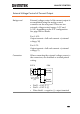
Falling:
For 10kΩ~0kΩ: Output voltage = full scale
voltage × ([10-external resistance]/10)
For 5kΩ~0kΩ: Output voltage = full scale
voltage × ([5-external resistance]/5)
Note
The falling resistance configuration is
recommended for safety reasons. In the event that
the cables become accidentaly disconnected (high
Ω), the voltage output will drop to zero. Under
similar circumstances using the rising resistance
configuaration, an unexpectedly high voltage
would be output.
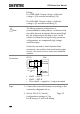
If swtiches are used to switch between fixed
resistances, use switches that avoid creating open
circuits. Use short-circuit or continous resistance
switches.
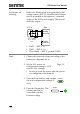
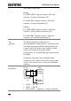
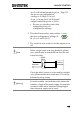
Connection
PSUEXT-R
Analog
connector
23
22
Output
Terminal
2 core shielded
wire or twisted
pair
Pin22 → EXT-R
Pin23 → EXT-R
Wire shield → negative (-) output terminal
Steps
1. Connect the external resistance according to the
connection diagrams above.
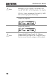
2. Set the F-90 (CV Control)
configuration settings to 2 for
Ext-R rising or 3 for Ext-R falling.
Page 111