Multi-Range DC Power Supply PSW Series USER MANUAL GW INSTEK PART NO.
This manual contains proprietary information, which is protected by copyright. All rights are reserved. No part of this manual may be photocopied, reproduced or translated to another language without prior written consent of Good Will company. The information in this manual was correct at the time of printing. However, Good Will continues to improve products and reserves the rights to change specification, equipment, and maintenance procedures at any time without notice. Good Will Instrument Co., Ltd. No.
SAFETY INSTRUCTIONS Table of Contents SAFETY INSTRUCTIONS ................................................... 5 GETTING STARTED ........................................................... 9 PSW Series Overview ........................... 10 Appearance .......................................... 14 Theory of Operation ............................. 20 OPERATION .................................................................... 31 Set Up .................................................. 33 Basic Operation .
PSW Series User Manual PSW Specifications ............................ 119 PSW Dimensions ............................... 128 Declaration of Conformity .................. 131 INDEX ............................................................................
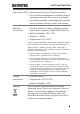
SAFETY INSTRUCTIONS SAFETY INSTRUCTIONS This chapter contains important safety instructions that you must follow during operation and storage. Read the following before any operation to insure your safety and to keep the instrument in the best possible condition. Safety Symbols These safety symbols may appear in this manual or on the instrument. WARNING Warning: Identifies conditions or practices that could result in injury or loss of life.
PSW Series User Manual Do not dispose electronic equipment as unsorted municipal waste. Please use a separate collection facility or contact the supplier from which this instrument was purchased. Safety Guidelines General Guideline CAUTION Do not place any heavy object on the PSW. Avoid severe impact or rough handling that leads to damaging the PSW. Do not discharge static electricity to the PSW. Use only mating connectors, not bare wires, for the terminals.
SAFETY INSTRUCTIONS Cleaning the PSW Operation Environment Disconnect the power cord before cleaning. Use a soft cloth dampened in a solution of mild detergent and water. Do not spray any liquid. Do not use chemicals containing harsh material such as benzene, toluene, xylene, and acetone.
PSW Series User Manual Power cord for the United Kingdom When using the power supply in the United Kingdom, make sure the power cord meets the following safety instructions.
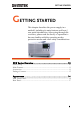
GETTING STARTED GETTING STARTED This chapter describes the power supply in a nutshell, including its main features and front / rear panel introduction. After going through the overview, please read the theory of operation to become familiar with the operating modes, protection modes and other safety considerations. PSW Series Overview ....................................................... 10 Series lineup ...................................................................................................
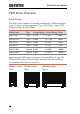
PSW Series User Manual PSW Series Overview Series lineup The PSW series consists of 6 models, divided into 3 different model types covering 3 power capacities: Type I (360 Watt), Type II (720 Watt) and Type III (1080 Watt). Model name Type Voltage Rating Current Rating Power PSW 30-36 Type I 0~30V 0~36A 360W PSW 80-13.5 Type I 0~80V 0~13.5A 360W PSW 30-72 Type II 0~30V 0~72A 720W PSW 80-27 Type II 0~80V 0~27A 720W PSW 30-108 Type III 0~30V 0~108A 1080W PSW 80-40.
GETTING STARTED Main Features Performance Features Interface High performance/power Power efficient switching type power supply Low impact on load devices Fast transient recovery time of 1ms Fast output response time OVP, OCP and OTP protection Adjustable voltage and current slew rates User adjustable bleeder control to quickly dissipate the power after shutdown to safe levels.
PSW Series User Manual 4320-91001101 Power cord (Type III) 63SC-XF100201 Output terminal cover: top 63SC-XF100301 Output terminal cover: bottom GTL-123 Test leads: 1x red, 1x black PSW-004 Basic Accessory Kit: M4 terminal screws and washers x2, M8 terminal bolts, nuts and washers x2, Air filter x1, Analog control protection dummy x1, Analog control lock level x1 Optional Accessories Part number Description GET-001 Extended terminal PSW-001 Accessory Kit: Pin contact x10, Socket x1, Protecti
GETTING STARTED Package Contents Check the contents before using the PSW.
PSW Series User Manual Appearance PSW Front Panel PSW 80-27, PSW 30-72 (720W) PSW 80-40.5, PSW 30-108 (1080W) PSW 80-13.
GETTING STARTED Function Keys The Function keys along with the Output key will light up when a key is active. The Function key is used to configure the power supply. Set the over current or over voltage protection levels. Sets the current and voltage limits. Used to run customized scripts for testing. Lock/Local Locks or unlocks the panel keys to prevent accidentally changing panel settings. Toggles the display from viewing V/AV/WA/W.
PSW Series User Manual 40 100 Sets the voltage. Voltage Knob Current Knob Power bar Indicates the current power output as a percentage. Current Sets the current. Output Press to turn on the output. The Output key will light up when the output is active. USB USB A port for data transfer, loading test scripts etc. Power Switch Used to turn the power on/off.
GETTING STARTED Rear Panel PSW 80-27, PSW 30-72 (720W) PSW 80-40.5, PSW 30-108 (1080W) PSW 80-13.5, PSW 30-36 (360W) AC Input SER.NO. LABEL N L LAN AC 100 47 63Hz 240V 1500VA MAX.
PSW Series User Manual Analog Control Connector Standard 26 pin MIL connector (OMRON XG4 IDC plug). The analog control connector is used to monitor current and voltage output, machine status (OVP, OCP, OTP etc.), and for analog control of the current and voltage output. Use an OMRON XG5 IDC socket as the mating socket. Output Terminals Positive (+) and negative (-) output terminals. Chassis ground Sense (-) and Sense (+) terminals. USB B port The USB B port is used for remote control.
GETTING STARTED Line Voltage Input (Type III) N L Type III: PSW 30-108/80-40.
PSW Series User Manual Theory of Operation The theory of operation chapter describes the basic principles of operation, protection modes and important considerations that must be taken into account before use. Operating Area Description Description The PSW power supplies are regulated DC power supplies with a high voltage and current output. These operate in CC or CV mode within a wide operating range limited only by the output power.
GETTING STARTED effective output is actually limited to the power limit of the unit. In this case the output current and voltage then depend purely on the load value. Below is a comparison of the operating areas of each power supply. PSW 80V Series Operating Area 4.5 9.0 27 13.5 40.5 90 80 80 Type I Type II Type III 60 40 26.
PSW Series User Manual CC and CV Mode CC and CV mode Description When the power supply is operating in constant current mode (CC) a constant current will be supplied to the load. When in constant current mode the voltage output can vary, whilst the current remains constant. When the load resistance increases to the point where the current limit (ISET) can no longer be sustained the power supply switches to CV mode. The point where the power supply switches modes is the crossover point.
GETTING STARTED Conversely the power supply will operate in CC mode when the load resistance is less than the critical resistance. In CC mode the current output is equal to ISET and the voltage output is less than VSET.
PSW Series User Manual Slew Rate Theory The PSW has selectable slew rates for CC and CV mode. This gives the PSW power supply the ability to limit the current/voltage draw of the power supply. Slew rate settings are divided into High Speed Priority and Slew Rate Priority. High Speed Priority mode disables slew rate settings for CC or CV mode. Slew Rate Priority mode allows for user adjustable slew rates for CC or CV mode. The rising and falling slew rate can be set independently.
GETTING STARTED may remain charged on the filter capacitors for some time and be potentially hazardous. In addition, bleed resistors also allow for smoother voltage regulation of the power supply as the bleed resistor acts as a minimum voltage load. The bleed resistance can be turned on or off using the configuration settings. Note By default the bleed resistance is on.
PSW Series User Manual Alarms The PSW power supplies have a number of protection features. When one of the protection alarms are set, the ALM icon on the display will be lit. For details on how to set the protection modes, please see page 43. OVP Overvoltage protection (OVP) prevents a high voltage from damaging the load. OCP Overcurrent protection prevents high current from damaging the load. OTP Over temperature protection protects the instrument from overheating.
GETTING STARTED Pulsed or Peaked loads When the load has current peaks or is pulsed, it is possible for the maximum current to exceed the mean current value. The PSW power supply ammeter only indicates mean current values, which means for pulsed current loads, the actual current can exceed the indicated value. For pulsed loads, the current limit must be increased, or a power supply with a greater capacity must be chosen.
PSW Series User Manual Note The current output will decrease by the amount of current absorbed by the resistor. Ensure the resistor used can withstand the power capacity of the power supply/load. Reverse Current: Accumulative energy. CAUTION When the power supply is connected to a load such as a battery, reverse current may flow back to the power supply. To prevent damage to the power supply, use a reverse-currentprotection diode in series between the power supply and load.
GETTING STARTED Grounding The output terminals of the PSW power supplies are isolated with respect to the protective grounding terminal. The insulation capacity of the load, the load cables and other connected devices must be taken into consideration when connected to the protective ground or when floating. Floating WARNING As the output terminals are floating, the load and all load cables must have an insulation capacity that is greater than the isolation voltage of the power supply.
PSW Series User Manual Grounded output terminal CAUTION 30 If the positive or negative terminal is connected to the protective ground terminal, the insulation capacity needed for the load and load cables is greatly reduced. The insulation capacity only needs to be greater than the maximum output voltage of the power supply with respect to ground. If using external voltage control, do not ground the external voltage terminal as this will create a short circuit.
OPERATION OPERATION Set Up ............................................................................. 33 Line Voltage Connection – Type III Models ....................................................... 33 Filter Installation ...................................................................................................... 35 Power Up .................................................................................................................. 36 Wire Gauge Considerations.......................
PSW Series User Manual Delete Test Script ....................................................................................................
OPERATION Set Up Line Voltage Connection – Type III Models Background Warning The Type III (PSW 30-108/PSW 80-40.5) models use a universal power input that can be used with 100 and 200 VAC systems. To connect or replace the power cord (GW Instek part number: 4320-91001101, use the procedure below: The following procedure should only be attempted by competent persons. Ensure the AC power cord is not connected to power. Removal 1. Turn off the power switch. 2. Unscrew the power cord protective sheath.
PSW Series User Manual 4. Slide the cover off the AC terminals. 5. Remove the AC power cord wires. Installation 1. Connect the AC power cord wires to the AC input terminals. White/Blue Neutral (N) Green/GreenyellowGND ( ) Black/Brown Line (L) 2. Set the cover back over the AC terminals. 3. Re-install the power cord cover. 4. Screw the power cord sheath back onto the cover.
OPERATION Filter Installation Background Steps The PSW has a small filter (GW Instek part number, 57RG-30B00101) that must first be inserted under the control panel before operation. The small filter must be inserted for all model types (Type I/II/II). 1. Insert the small filter in the open area under the control panel. Type II shown as an example 2. The unit is now ready to power up.
PSW Series User Manual Power Up Steps 1. Type I or II: Connect the power cord to the rear panel socket. Type III: Connect the power cord to the universal power input. Page 33 2. Press the POWER key. If used for the first time, the default settings will appear on the display, otherwise The PSW recovers the state right before the power was last turned OFF. For default configuration settings, see page 116. CAUTION The power supply takes around 8 seconds to fully turn on and shutdown.
OPERATION Wire Gauge Considerations Background Before connecting the output terminals to a load, the wire gauge of the cables should be considered. It is essential that the current capacity of the load cables is adequate. The rating of the cables must equal or exceed the maximum current rated output of the instrument. Recommended wire gauge Wire Gauge 20 18 16 14 12 10 8 6 4 Maximum Current 2.
PSW Series User Manual Output Terminals Background Before connecting the output terminals to the load, first consider whether voltage sense will be used, the gauge of the cable wiring and the withstand voltage of the cables and load. The output terminals can be connected to load cables using M4 sized screws or M8 sized bolts. WARNING Dangerous voltages. Ensure that the power to the instrument is disabled before handling the power supply output terminals. Failing to do so may lead to electric shock. 1.
OPERATION 5. Choose a suitable crimp for the terminals. 6. If using voltage sense, remove the Page 50 sense terminal joining plates and connect sensing wires to the load(s). 7. Connect the positive load cable to the positive output terminal and the negative cable to the negative output terminal. 8. Reattach the output terminal cover.
PSW Series User Manual Using the Output Terminal Cover Background 1. Line-up the bottom cover with the notch in the output terminals. 2. Place the top terminal cover over the bottom cover. 3. Use your thumb to slide the terminal covers shut, as shown in the diagram below. 4. The top and bottom cover should be flush, as shown in the diagram.
OPERATION Removal Reverse the procedure to remove the terminal covers. Using the Rack Mount Kit Background Rack mount diagram The PSW series has an optional Rack Mount Kit (GW Instek part number: [JIS] GRA-410-J, [EIA] GRA-410-E[EIA]) that can be used to hold 6x PSW Type I models, 3x Type II models, 2x Type III models or a combination of all models (1x Type I, 1x Type II and 1x Type III).
PSW Series User Manual 1. Repeatedly press the voltage knob until the last digit is highlighted. This will allow the voltage to be edited in 0.01 volt steps. 2. Turn the voltage knob till 0.05 volts is shown. → V A 3. Repeatedly press the voltage knob until the first digit is highlighted. This will allow the voltage to be edited in 1 volt steps. 4. Turn the voltage knob until 10.05 is shown. V → A Note Notice the Set key becomes illuminated when setting the current or voltage.
OPERATION Basic Operation This section describes the basic operations required to operate the power supply. Setting OVP/OCP → from page 43 C.V. mode → from page 45 C.C. mode → from page 47 Display modes → page 49 Panel lock → page 50 Remote sensing → from page 50 Before operating the power supply, please see the Getting Started chapter, page 9.
PSW Series User Manual 1. Press the OVP/OCP key. The OVP/OCP key lights up. 2. The OVP setting will be displayed on the top and the OCP setting will be displayed on the bottom. OVP Level 3. Use the voltage knob to set the OVP level. Range OCP Level 10%~110% of rated output voltage. 4. Use the current knob to set the OCP level. Range Voltage Current 10%~110% of rated output current. 5. Press OVP/OCP again to exit. The OVP/OCP indicator will turn off. Power switch trip 6.
OPERATION Set to C.V. Mode When setting the power supply to constant voltage mode, a current limit must also be set to determine the crossover point. When the current exceeds the crossover point, the mode switches to C.C. mode. For details about C.V. operation, see page 20. C.C. and C.V. mode have two selectable slew rates: High Speed Priority and Slew Rate Priority. High Speed Priority will use the fastest slew rate for the instrument while Slew Rate Priority will use a user-configured slew rate.
PSW Series User Manual 4. Use the Current knob to set the current limit (crossover point). 5. Use the Voltage knob to set the voltage. Note Voltage Notice the Set key becomes illuminated when setting the current or voltage. If the voltage or current knobs are unresponsive, press the Set key first. 6. Press the Output key. The Output key becomes illuminated. Note 46 Only the voltage level can be altered when the output is on. The current level can only be changed by pressing the Set key.
OPERATION Set to C.C. Mode When setting the power supply to constant current mode, a voltage limit must also be set to determine the crossover point. When the voltage exceeds the crossover point, the mode switches to C.V. mode. For details about C.C. operation, see page 20. C.C. and C.V. mode have two selectable slew rates: High Speed Priority and Slew Rate Priority. High Speed Priority will use the fastest slew rate for the instrument while Slew Rate Priority will use a user-configured slew rate.
PSW Series User Manual F-06 F-07 Note 0.01A/s~72.00A/s (PSW 30-36) 0.01A/s~144.0A/s (PSW 30-72) 0.01A/s~216.0A/s (PSW 30-108) 0.01A/s~27.00A/s (PSW 80-13.5) 0.01A/s~54.00A/s (PSW 80-27) 0.01A/s~81.00A/s (PSW 80-40.5) 4. Use the Voltage knob to set the voltage limit (crossover point). Voltage 5. Use the Current knob to set the current. Current Notice the Set key becomes illuminated when setting the current or voltage. If the voltage or current knobs are unresponsive, press the Set key first. 6.
OPERATION Display Modes The PSW power supplies allow you to view the output in three different modes: voltage and current, voltage and power or current and power. 1. Press the PWR/DSPL key. The PWR DSPL key lights up. 2. The display changes to voltage and power (V/W). 3. To switch between displaying A/W and V/W, simply press the corresponding voltage or current knob. For example: when in A/W mode, press the voltage knob to display V/W. Conversely when in V/W mode, press the current knob to display A/W.
PSW Series User Manual Panel Lock The panel lock feature prevents settings from being changed accidentally. When activated, the Lock/Local key will become illuminated and all keys and knobs except the Lock/Local key and Output key (if active) will be disabled. If the instrument is remotely controlled via the USB/LAN interface, the panel lock is automatically enabled. Activate the panel lock Press the Lock/Local key to active the panel lock. The key will become illuminated.
OPERATION WARNING Ensure the output is off before connecting any sense cables. Use sense cables with a voltage rating exceeding the isolation voltage of the power supply. Never connect sensing cables when the output is on. Electric shock or damage to the power supply could result. Note Single Load Be sure to remove the Sense joining plates so the units are not using local sensing. 1. Connect the Sense+ terminal to the positive potential of the load.
PSW Series User Manual Parallel PSW Units 1. Connect the Sense+ terminals to the positive potential of the load. Connect the Senseterminals to the negative potential of the load. Page 38 2. Operate the instrument as normal. Page 55 See the Parallel Operation chapter for details. Serial PSW Units 1. a. Connect the 1st Sense+ terminal to the positive potential of the load. b. Connect the 1st Sense- terminal to the positive output terminal of the second PSW unit. c.
OPERATION Page 38 2. Operate the instrument as normal. Page 61 See the Serial Operation chapter for details. Wire Shielding and Load line impedance To help to minimize the oscillation due to the inductance and capacitance of the load cables, use an electrolytic capacitor in parallel with the load terminals. To minimize the effect of load line impedance use twisted wire pairing.
PSW Series User Manual Parallel / Series Operation This section describes the basic operations required to operate the power supply in series or parallel. Operating the PSW series in parallel increases the total power output of the power supply units. When used in series, the total output voltage of the power supplies can be increased.
OPERATION Master-Slave Parallel Overview Description When connecting the PSW power supplies in parallel, up to 3 units can be used in parallel and all units must be of the same model. When the units are used in parallel, a number of precautions and limitations apply. Please read this overview before operating the power supplies in parallel. Limitations Display Only the master unit will display the voltage and current.
PSW Series User Manual Output Voltage/ Output Current Model PSW 30-36 PSW 80-13.5 PSW 30-72 PSW 80-27 PSW 30-108 PSW 80-40.5 Single unit 30V 36A 80V 13.5A 30V 72A 80V 27A 30V 108A 80V 40.5A 2 units 30V 72A 80V 27A 30V 144A 80V 54A 30V 216A 80V 81A 3 units 30V 108A 80V 40.5A 30V 216A 80V 81A 30V 324A 80V 121.5A Master-Slave Parallel Connection Master-Slave Connector The Analog Control Connector is used for both serial and parallel connections.
OPERATION Master with 2 slave units: Master with 1 slave unit: 26 23 21 17 15 13 11 12 20 2 23 17 15 26 24 20 Master unit 3 1 12 Slave Unit 1 11 I MON 1 CURRENT SHARE 21 OUTPUT ON STATUS 24 OUT ON/OFF CONT 20 ALM STATUS 12 SHUTDOWN 17 STATUS COM 17 STATUS COM 15 FEEDBACK 15 FEEDBACK 13 CURRENT_SUM_1 3 CURRENT SUM OUT 12 SHUTDOWN 20 ALM STATUS 2 D COM 26 DETECT OUT 23 DETECT IN 23 DETECT IN 26 DETECT OUT 57
PSW Series User Manual Parallel Output Connection Steps 1. Ensure the power is off on all power supplies. 2. Choose a master and a slave unit(s). 3. Connect the analog connectors for the master and slave unit as shown above. Page 40 4. Remove the Output Terminal covers and the protection dummy plug from the analog control connector. 5. Connect the master and slave unit in parallel as shown above. 6. Reattach the terminal covers.
OPERATION Master-Slave Parallel Operation Master-Slave Configuration Before using the power supplies in parallel, the master and slave units need to be configured. 1. Configure the OVP and OCP settings for the master unit. Page 43 2. For each unit, hold the Function key while turning the power on to enter the power on configuration settings. Page 86 3. Configure F-93 (Master/Slave) setting for each master/slave unit.
PSW Series User Manual Master-Slave Operation Only operate the power supplies in parallel if the units are configured correctly. 1. Turn on the master and slave units. The slave unit(s) will show a blank display. Master unit Slave units 2. Operation of all units is controlled Page 43. via the master unit. Operation of the master unit is the same as for a single unit. See the Basic Operation chapter. 3. Press the Output key to begin.
OPERATION Master-Slave Series Overview Background When connecting PSW power supplies in series, up to 2 units can be used in series and all units must be of the same model. When the units are used in series, a number of precautions and limitations apply. Please read this overview before operating the power supplies in series. Limitations Display Only the master unit will display the current. Master and slave units display the voltage. The total voltage is the sum of the units.
PSW Series User Manual Output Voltage/ Output Current Voltage controlled remote control Voltage controlled remote control can only be used with the master unit. Model Single unit 2 units PSW 30-36 30V 60V 36A 36A PSW 80-13.5 80V 160V 13.5 13.5A PSW 30-72 30V 60V 72A 72A PSW 80-27 80V 160V 27A 27A PSW 30-108 30V 60V 108A 108A PSW 80-40.5 80V 160V 40.5A 40.5A Master-Slave Series Connection Master-Slave Connector The Analog Control Connector is used for both serial and parallel connections.
OPERATION Series Output Connection - Steps Load + Master unit Slave unit 1. Ensure the power is off on both power supplies. 2. Choose a master and slave unit. 3. Connect the analog connectors for the master and slave unit as shown above. 4. Remove the output terminal cover Page 40 and the protection dummy plug from the analog control connector. 5. Connect the master and slave unit in series as shown above. 6. Reattach the terminal cover.
PSW Series User Manual Note Ensure load cables have sufficient current capacity. Page 37 Re-attach the protection dummy plug when not in use. Master-Slave Series Operation Master-Slave Configuration Before using the power supplies in series, the master and slave units need to be configured. 1. Configure the OVP and OCP settings for the master unit. Page 43 2. For each unit, hold the Function key while turning the power on to enter the power on configuration settings.
OPERATION 1. Turn on the master and slave unit. The slave unit will only show the voltage. Master unit Slave units 2. Operation of all units is controlled Page 43 via the master unit. Operation of the master unit is the same as for a single unit. Please see the basic operation chapter for details. 3. Press the Output key to begin. CAUTION Output Only operate the power supplies in series if using units of the same model number. Only a maximum of 2 units can be used in series.
PSW Series User Manual Test Scripts This section describes how to use the Test function to run, load and save test scripts for automated testing. The Test function is useful if you want to perform a number of tests automatically. The PSW test function can store ten test scripts in memory. Each test script is programmed in a scripting language. For more information on how to create Test Scripts, please see the programming manual.
OPERATION Test Script File Format Description The test files are saved in *.tst file format. Each file is saved as tXXX.tst, where XXX is the save file number 001~010. Test Script Settings Test Run Runs the chosen test script from the internal memory. A script must first be loaded into the internal memory before it can be run. See the test function Test Save, below. The script will run as soon as the test function is started.
PSW Series User Manual Setting the Test Function Settings Steps The test script settings (T-01~T-04) are set with the Test key. 1. Press the Test key. The Test key will light up. 2. The display will show T-01 on the top and the memory no. for T-01 on the bottom. Test Setting Memory number 3. Rotate the voltage knob to change the T setting (Test setting). Test Run T-01 Test Load T-02 Test Export T-03 Test Remove T-04 4. Rotate the current knob to choose a memory number. Range 1~10 5.
OPERATION Exit Press the Test key again to exit the Test settings. The Test key light will turn off. Load Test Script from USB Overview Before a test script can be run, it must first be loaded into a one of the 10 memory save slots. Before loading a test script into memory: Ensure the script file is placed in the root directory. Ensure the file name number corresponds to the memory number that you wish to save to. For example: A test file named t001.
PSW Series User Manual Note If the USB drive is not recognized, check to see that the function settings for F-20 = 1 (page 80). If not, reinsert the USB flash drive. 3. Configure T-02 (Test Load) to 1~10 Page 68 (save memory slot) T-02 range 1~10 (t001 ~t010) 4. The script will now be available in the memory slot the script was saved to. Note Error messages: If you load a file that is not present on the USB drive “Err 002” will be displayed on the display.
OPERATION Note Error messages: If you try to run a test script from an empty memory location “Err 003” will be displayed on the display. Note When a script starts to run, there is no way to abort the script. Pressing the Output key has no effect. If you wish to stop a test early, turn the power off. Export Test Script to USB Overview Steps The Export Test function saves a test file to the root directory of a USB flash drive. Files will be saved as tXXX.
PSW Series User Manual If the USB drive is not recognized, check to see that the function settings for F-20 = 1 (page 80). If not, reinsert the USB flash drive. Note 3. Configure T-03 (Test Export) to 0~10 (save memory slot) Page 68 T-03 range 1~10 4. The script will now be copied to the USB flash drive. Error messages: If you try to export a test script from an empty memory location “Err 003” will be displayed on the display.
OPERATION Note Error messages: If you try to remove a test script from an empty memory location “Err 003” will be displayed on the display.
PSW Series User Manual CONFIGURATION Configuration .................................................................. 75 Configuration Table ................................................................................................ 75 Normal Function Settings ...................................................................................... 78 USB/GPIB Settings ................................................................................................ 80 LAN Settings .......................
CONFIGURATION Configuration Configuration of the PSW power supplies is divided into five different configuration settings: Normal Function, USB/GPIB, LAN, Power ON Configuration and Calibration Settings. Power ON Configuration differs from the other settings in that the settings used with Power ON Configuration settings can only be set during power up. The other configuration settings can be changed when the unit is already on.
PSW Series User Manual Falling current slew rate F-07 Internal resistance setting F-08 Bleeder circuit control F-09 Buzzer ON/OFF control F-10 USB/GPIB settings Front panel USB State F-20 0.01A/s~72.00A/s (PSW 30-36) 0.1A/s~144.0A/s (PSW 30-72) 0.1A/s~216.0A/s (PSW 30-108) 0.01A/s~27.00A/s (PSW 80-13.5) 0.01A/s~54.00A/s (PSW 80-27) 0.01A/s~81.00A/s (PSW 80-40.5) 0.000Ω~0.833Ω (PSW 30-36) 0.000Ω~0.417Ω (PSW 30-72) 0.000Ω~0.278Ω (PSW 30-108) 0.000Ω~5.926Ω (PSW 80-13.5) 0.000Ω~2.963Ω (PSW 80-27) 0.000Ω~1.
CONFIGURATION Gateway-3 F-49 Gateway-4 F-50 DNS address -1 F-51 DNS address -2 F-52 DNS address-3 F-53 DNS address-4 F-54 Sockets active F-57 Web Server active F-59 Web password active F-60 Web setting password F-61 Power On Configuration Settings* 0~255 0~255 0~255 0~255 0~255 0~255 0 = Disable, 1 = Enable 0 = Disable, 1 = Enable 0 = Disable, 1 = Enable 0000~9999 CC Control F-91 Power-ON Output F-92 Master/Slave F-93 External Out Logic Power Switch trip Calibration Settings* Calibration F-94 F-95
PSW Series User Manual Normal Function Settings Output ON Delay Time Delays turning the output on for a designated amount of time. The Delay indicator will light when the Delay time is not 0. F-01 Output OFF Delay Time Delays turning the output off for a designated amount of time. The Delay indicator will light when the Delay time is not 0. F-02 V-I Mode 78 0.00s~99.99s 0.00s~99.99s Selects High Speed Priority, or Slew Rate Priority CV or CC mode.
CONFIGURATION F-03 0 = CV high speed priority 1 = CC high speed priority 2 = CV slew rate priority 3 = CC slew rate priority Rising Voltage Slew Rate Sets the rising voltage slew rate. Only applicable if V-I Mode is set to CV Slew Rate Priority. F-04 0.01V/s~60V/s (PSW 30-XX) 0.1V/s~160V/s (PSW 80-XX) Falling Voltage Slew Rate Sets the falling voltage slew rate. Only applicable if V-I Mode is set to CV Slew Rate Priority. F-05 0.01V/s~60V/s (PSW 30-XX) 0.
PSW Series User Manual Internal Resistance Settings Sets the internal resistance of the power supply. F-08 0.000Ω~0.833Ω (PSW 30-36) 0.000Ω ~0.417Ω (PSW 30-72) 0.000Ω ~0.278Ω (PSW 30-108) 0.000Ω ~5.926Ω (PSW 80-13.5) 0.000Ω ~2.963Ω (PSW 80-27) 0.000Ω ~1.975Ω (PSW 80-40.5) Bleeder Control Bleeder control turns ON/OFF the bleeder resistor. Bleeder resistors discharge the filter capacitors after power is turned off as a safety measure. F-09 0 = OFF, 1 = ON Buzzer ON/OFF Turns the buzzer sound on or off.
CONFIGURATION LAN Settings MAC Address1~6 Displays the MAC address 1~6. This setting is not configurable. F-30~F-35 0x00~0xFF LAN Turns Ethernet on or off. F-36 0 = Disable, 1 = Enable DHCP Turns DHCP on or off. F-37 0 = Disable, 1 = Enable IP Address-1~4 Sets the default IP address. IP address 1~4 splits the IP address into four sections. (F-39 : F-40 : F-41 : F-42) (0~255 : 0~255 : 0~255 : 0~255) Subnet Mask 1~4 Sets the subnet mask. The subnet mask is split into four parts.
PSW Series User Manual Web Password active Turns a web password on/off. F-60 Web Password 82 0 = Disable, 1 = Enable Sets the Web password.
CONFIGURATION Power On Configuration Settings CV Control Sets the constant voltage (CV) control mode between local and external voltage/resistance control. For external voltage control, see page 91 (External Voltage Control of Voltage Output) and page 95 (External Resistance Control of Voltage Output).
PSW Series User Manual F-93 0 = Master/Local 1 = Master/Parallel1 2 = Master/Parallel2 3 = Slave/Parallel 4 = Slave/Series External Out Logic Sets the external logic as active high or low. F-94 0= High ON, 1 = Low ON Power Switch Trip Turns the power off if enabled when the protection settings are tripped. F-95 1 = Disable, 0 = Enable Calibration Programmable Calibration The calibration password is used to access the local mode calibration or other special functions.
CONFIGURATION 2. The display will show F-01 on the top and the configuration setting for F-01 on the bottom. 3. Rotate the voltage knob to change the F setting. Range Voltage F-00~ F-95 4. Use the current knob to set the parameter for the chosen F setting. Current 5. Press the Voltage knob to save the configuration setting. Save will be displayed when successful. Exit Press the Function key again to exit the configuration settings. The function key light will turn off.
PSW Series User Manual Setting Power On Configuration Settings The Power On configuration settings can only be changed during power up to prevent the configuration settings being inadvertently changed. Ensure the load is not connected. Ensure the power supply is off. 1. Hold the Function key whilst turning the power on. 2. The display will show F-90 on the top and the configuration setting for F-90 on the bottom. 3. Rotate the voltage knob to change the F setting. Range F-90~ F-95 4.
CONFIGURATION 5. Press the Voltage knob to save the configuration setting. ConF will be displayed when successful. Exit Voltage Cycle the power to save and exit the configuration settings.
PSW Series User Manual ANALOG CONTROL The Analog Control chapter describes how to control the voltage or current output using an external voltage or resistance, monitor the voltage or current output as well as remotely turning off the output or shutting down the power supply. Analog Remote Control Overview .................................... 89 Analog Control Connector Overview................................................................... 89 External Voltage Control of Voltage Output ..............
ANALOG CONTROL Analog Remote Control Overview The PSW power supply series have a number of analog control options. The Analog Control connectors are used to control output voltage and current using external voltage or resistance. The power supply output and power switch can also be controlled using external switches.
PSW Series User Manual D COM CURRENT SUM OUT EXT-V CV CONT EXT-V CC CONT EXT-R CV CONT PIN1 EXT-R CV CONT PIN2 EXT-R CC CONT PIN1 EXT-R CC CONT PIN2 V MON I MON SHUTDOWN CURRENT_SUM_ 1 CURRENT_SUM_ 2 FEEDBACK 90 2 Connected to the (–S) sense- terminal when remote sense is used. Connected to the negative output terminal when remote sense is not used. 3 Current sum output signal when used in parallel mode. 4 External voltage control of the voltage output.
ANALOG CONTROL A COM STATUS COM CV STATUS CC STATUS ALM STATUS OUTPUT ON STATUS POWER OFF STATUS DETECT IN OUT ON/OFF CONT SER SLV IN DETECT OUT 16 Analog signal common. Connected to the senseterminal when remote sense is used. Connected to the negative output terminal when remote sense is not used. 17 Common for status signals 18, 19, 20, 21 and 22. 18 Turns on when CV mode is active. (photo coupled open collector output) 19 Turns on when CC mode is active.
PSW Series User Manual Connection When connecting the external voltage source to the MIL connectors, use shielded or twisted paired wiring. Connection- alt. shielding If the wire shield needs to be grounded at the voltage source (EXT-V), then the shield cannot also be grounded at the negative (-) terminal output of the PSW power supply. This would short the output.
ANALOG CONTROL Page 86 2. Set the F-90 power on configuration setting to 1 (CV control – Ext voltage). Be sure to cycle the power after the power on configuration has been set. 3. Press the Function key and confirm the new configuration settings (F90=1). 4. Press the Output key. The voltage can now be controlled with the External voltage. Note The input impedance for external voltage control is 10kΩ. Use a stable voltage supply for the external voltage control. CAUTION Ensure no more than 10.
PSW Series User Manual Connection When connecting the external voltage source to the MIL connectors, use shielded or twisted paired wiring. Connection- alt. shielding If the wire shield needs to be grounded at the voltage source (EXT-V), then the shield cannot also be grounded at the negative (-) terminal output of the PSW power supply. This would short the output.
ANALOG CONTROL Page 86 2. Set the F-91 power on configuration setting to 1 (CC control – Ext voltage). Be sure to cycle the power after the power on configuration has been set. 3. Press the Function key and confirm the new configuration settings (F91=1). 4. Press the Output key. The current can now be controlled with the External voltage. Note CAUTION The input impedance for external voltage control is 10kΩ. Use a stable voltage supply for the external voltage control.
PSW Series User Manual (Ext-R ) 10kΩ~0kΩ(10kΩ = 0). For 0kΩ~10kΩ: Output voltage = full scale voltage × (external resistance/10) For 10kΩ~0kΩ: Output voltage = full scale voltage × ([10-external resistance]/10) Note The Ext-R configuration is recommended for safety reasons. In the event that the cables become accidentaly disconnected, the voltage output will drop to zero. Under similar circumstances using Ext-R , an unexpected high voltage would be output.
ANALOG CONTROL 3. Press the Function key and confirm the new configuration settings (F90=2 or 3). 4. Press the Output key. The voltage can now be controlled with the External resistance. Note Ensure the resistor(s) and cables used exceed the isolation voltage of the power supply. For example: insulation tubes with a withstand voltage higher than the power supply can be used. When choosing an external resistor ensure the resistor can withstand a high degree of heat.
PSW Series User Manual Note The Ext-R configuration is recommended for safety reasons. In the event that the cables become accidentaly disconnected, the current output will drop to zero. Under similar circumstances using Ext-R , an unexpected high current would be output. If swtiches are used to switch between fixed resistances, use switches that avoid creating open circuits. Use short-circuit or continous resistance switches.
ANALOG CONTROL 3. Press the Output key. The current can now be controlled with the External resistance. Note Ensure the resistor(s) and cables used exceed the isolation voltage of the power supply. For example: insulation tubes with a withstand voltage higher than the power supply can be used. When choosing an external resistor ensure the resistor can withstand a high degree of heat. External Control of Output Description The output can be turned on or off externally using a switch.
PSW Series User Manual Connection Panel operation Pin2 → Switch Pin24 → Switch Wire shield → negative (-) output terminal 1. Connect the external switch according to the connection diagrams above. Set F-94 (External output logic) in Page 86 the power on configuration settings to 0 (High = On) or 1 (Low = On). Be sure to cycle the power after setting the power on configuration settings. 2. Press the Function key and confirm the new configuration settings. 3.
ANALOG CONTROL Note When using a switch over long distances, please use a switch relay to extend the line from the coil side of the relay. If a single switch control is to be used for multiple units, please isolate each instrument. This can be achieved by using a relay. Warning Note Ensure the cables used and the switch exceed the isolation voltage of the power supply. For example: insulation tubes with a withstand voltage higher than the power supply can be used.
PSW Series User Manual External control of Shutdown Description The output of the power supplies can be configured to shut down via an external switch. The ability to externally shut down the power supply must first be enabled in the power on configuration settings. The voltage across pins 2 and 12 are internally pulled to +5V ±5% @ 500uA with 10kΩ pull-up resistor. Connection Panel operation Pin2 → Switch Pin12 → Switch Wire shield → negative (-) output terminal 1.
ANALOG CONTROL Note When using a switch over long distances, please use a switch relay to extend the line from the coil side of the relay. If a single switch control is to be used for multiple units, please isolate each instrument. This can be achieved by using a relay. Warning Ensure the cables and switch used exceed the isolation voltage of the power supply. For example: insulation tubes with a withstand voltage higher than the power supply can be used.
PSW Series User Manual Remote Monitoring The PSW power supplies have remote monitoring support for current and voltage output. They also support monitoring of operation and alarm status. External monitoring of output voltage and current → from page 104 External monitoring of operation mode and alarm status → from page 106 External Voltage and Current Monitoring Background The MIL 26 pin connector is used to monitor the current (IMON) or voltage (VMON) output.
ANALOG CONTROL PSW VMON Connection DMM 10 V MON 0→10V 16 Analog connector Output Terminal Pin16 → Neg (-) Pin10 → Pos (+) IMON Connection Note Pin16 → Neg (-) Pin11 → Pos (+) The output impedance of the voltage (VMON) and current (IMON) monitor pins is 1kΩ. Maximum current is 10mA. The monitor outputs are strictly DC and should not be used to monitor analog components such as transient voltage response or ripple etc.
PSW Series User Manual External Operation and Status Monitoring Background The MIL 26 pin connector can also be used to monitor the status operation and alarm status of the instrument. The pins are isolated from the power supply internal circuitry by photo couplers. Status Com (Pin 17) is a photo coupler emitter output, whilst pins 18~22 are photo coupler collector outputs. A maximum of 30V and 8mA can be applied to each pin.
COMMUNICATION INTERFACE COMMUNICATION INTERFACE This chapter describes basic configuration of IEEE488.2 based remote control. For a command list, refer to the programming manual, downloadable from GW Instek website, www.gwinstek.com Interface Configuration .................................................. 108 USB Remote Interface .......................................................................................... 108 Configure GPIB Interface ........................................................
PSW Series User Manual Interface Configuration USB Remote Interface USB configuration Panel operation PC side connector Type A, host PSW side connector Rear panel Type B, slave Speed 1.1/2.0 (full speed/high speed) USB Class CDC (communications device class) 1. Connect the USB cable to the rear panel USB B port. 2. Change the Rear panel-USB (F-22) Page 84 setting to USB-CDC (2). Configure GPIB Interface To use GPIB, the optional GPIB to USB (GUG-001) adapter must be used.
COMMUNICATION INTERFACE Type A plug From computer Type B plug for PSW series GUG-001 4. Turn the PSW on. 5. Press the Function key to enter the Page 84 Normal configuration settings.
PSW Series User Manual Settings DHCP IP Address Subnet Mask Gateway DNS Address Sockets Active Web Server Active Web Password Active Web set password 0000~9999 (default 0000) Connection Connect an Ethernet cable from the network to the rear panel Ethernet port. DHCP Connection Example Use the Following configuration settings to use Dynamic Host Configuration Protocol. The following settings will also automatically assign an IP address. 6.
COMMUNICATION INTERFACE remote control (page 108). *idn? This should return the Manufacturer, Model number, Serial number, and Firmware version in the following format. GW-INSTEK,PSW-3036,TW123456,01.00.20110101 Manufacturer: GW-INSTEK Model number : PSW-3036 Serial number : TW123456 Firmware version : 01.00.20110101 Note ^j can be used as the terminal character when entering the queries/commands from a terminal application.
PSW Series User Manual MAINTENANCE The PSW power supply filters should be replaced on a periodic schedule to maintain performance and specification characteristics. Replacing the Dust Filter ......................................................................................
MAINTENANCE Replacing the Dust Filter The dust filter should be replaced at least 2 times a year. Not replacing the filter on a regular basis will reduce performance and may cause the unit to overheat. Front panel filter 7. Turn the instrument off. (all models) 8. Pull the filter out from the bottom of the front panel. 9. Replace the filter with GW Instek part number 57RG-30B00101. Side panel filters 1. Lift the side panel up (Type II & Type and away from the III) case. 2.
PSW Series User Manual FAQ • The power supply won’t let me change the mode (C.V. mode ↔ C.C. mode). • The OVP voltage is triggered earlier than expected. • Can I combine more than 1 cable together for the output wiring? • The accuracy does not match the specification. The power supply won’t let me change the mode (C.V. mode ↔ C.C. mode). To set the power supply to CC or CV mode, the Function key must be held when the power is turned on to enter the Power On Configuration Mode. See page 83.
FAQ The accuracy does not match the specification. Make sure the device is powered On for at least 30 minutes, within +20°C~+30°C. This is necessary to stabilize the unit to match the specification. For more information, contact your local dealer or GWInstek at www.gwinstek.com / marketing@goodwill.com.tw.
PSW Series User Manual APPENDIX PSW Default Settings The following default settings are the factory configuration settings for the power supply (Function settings/Test settings). Normal Function Settings Output ON delay time Output OFF delay time V-I mode slew rate select Rising voltage slew rate Setting F-01 F-02 F-03 F-04 F-08 Default Setting 0.00s 0.00s 0 = CV high speed priority 60.00V/s (PSW 30-XX) 160.0V/s (PSW 80-XX) 60.00V/s (PSW 30-XX) 160.0V/s (PSW 80-XX) 72.00A/s (PSW 30-36) 144.
APPENDIX Rear panel USB State Rear Panel USB Mode GPIB address LAN setting MAC Address-1 MAC Address-2 MAC Address-3 MAC Address-4 MAC Address-5 MAC Address-6 LAN DHCP IP Address-1 IP Address-2 IP Address-3 IP Address-4 Subnet Mask-1 Subnet Mask-2 Subnet Mask-3 Subnet Mask-4 Gateway-1 Gateway-2 Gateway-3 Gateway-4 DNS address -1 DNS address -2 DNS address-3 DNS address-4 Sockets active Web Server active Web password active Web setting password Power On Configuration CV Control CC Control Power-ON Output Ma
PSW Series User Manual Test Setting Test Run Test Load Test Export Test Remove T-01 T-02 T-03 T-04 1 1 1 1 Error Messages & Messages The following error messages or messages may appear on the PSW screen during operation. Error Messages Err 001 Err 002 Err 003 Description USB Mass Storage is not present No (such)file in USB mass storage Empty memory location Messages MSG 001 Description External control of output. Output off (F-94=0, High=on) External control of output.
APPENDIX PSW Specifications The specifications apply when the PSW is powered on for at least 30 minutes. PSW 30-36, PSW 80-13.5 Model DC Output Ratings: PSW 30-36 PSW 80-13.5 Voltage 30V 80V Current 36A 13.5A Power 360W 360W Load Effect: Voltage 0.05% of rating + 5mV 0.05% of rating + 5mV Current 0.1% of rating + 5mA 0.1% of rating + 5mA Source Effect: (change from 85-132 VAC input or 170-265 VAC input) Voltage 0.05% of rating + 3mV 0.05% of rating + 3mV Current 0.1% of rating + 5mA 0.
PSW Series User Manual Temperature Coefficient: (after a 30 minute warm-up) Voltage 100ppm/˚C Current 200ppm/˚C Temperature Drift: (over 8 hours, after a 30 minute warm-up, with constant line, load, and temperature) Voltage 15mV 40mV (0.05% of rated Vo) Current 18mA 6.75mA (0.
APPENDIX AC Input: Input General Nominal Input Input Range Frequency Hold up Time Input Current Power (max) Power Factor (typ) Efficiency (typ) Inrush Current Weight Dimensions 100 - 240 VAC; 50/60Hz 85VAC ~ 265VAC 47Hz ~ 63Hz >20ms (at rated load) 5A@100VAC / 2.5A@200VAC 500VA 0.98 75% 78% <15Apeak Approx.
PSW Series User Manual PSW 30-72, PSW 80-27 Model DC Output Ratings: PSW 30-72 PSW 80-27 Voltage 30V 80V Current 72A 27A Power 720W 720W Load Effect: Voltage 0.05% of rating + 5mV 0.05% of rating + 5mV Current 0.1% of rating + 5mA 0.1% of rating + 5mA Source Effect: (change from 85-132 VAC input or 170-265 VAC input) Voltage 0.05% of rating + 3mV 0.05% of rating + 3mV Current 0.1% of rating + 5mA 0.
APPENDIX Voltage 15mV 40mV (0.05% of rated Vo) Current 36mA 13.5mA (0.05% of rated Io) OVP setting 10% to 110% of rated output voltage Protection Function range OVP accuracy 1% OCP setting 10% to 110% of rated output current range OCP accuracy 1% OTP Activated by elevated internal temperatures Analog Programming and monitoring EXT-V Control Accuracy & linearity = +/-0.5% of rated Vout Vo EXT-V Control Accuracy & linearity = +/-1% of rated Iout Io EXT-R Control Accuracy & linearity = +/-1.
PSW Series User Manual General 124 Power (max) Power Factor (typ) Effidiency (typ) Inrush Current Weight Dimensions 1000VA 0.98 75% 78% <30Apeak Approx.
APPENDIX PSW 30-108, PSW 80-40.5 Model DC Output Ratings: PSW 30-108 PSW 80-40.5 Voltage 30V 80V Current 108A 40.5A Power 1080W 1080W Load Effect: Voltage 0.05% of rating + 5mV 0.05% of rating + 5mV Current 0.1% of rating + 5mA 0.1% of rating + 5mA Source Effect: (change from 85-132 VAC input or 170-265 VAC input) Voltage 0.05% of rating + 3mV 0.05% of rating + 3mV Current 0.1% of rating + 5mA 0.
PSW Series User Manual Voltage 15mV 40mV (0.05% of rated Vo) Current 54mA 20.25mA (0.05% of rated Io) OVP setting 10% to 110% of rated output voltage Protection Function range OVP accuracy 1% OCP setting 10% to 110% of rated output current range OCP accuracy 1% OTP Activated by elevated internal temperatures Analog Programming and Monitoring EXT-V Control Accuracy & linearity = +/-0.5% of rated Vout Vo EXT-V Control Accuracy & linearity = +/-1% of rated Iout Io EXT-R Control Accuracy & linearity = +/-1.
APPENDIX General Power (max) Power Factor (typ) Effidiency (typ) Inrush Current Weight Dimensions 1500VA 0.98 75% 78% <45Apeak Approx.
PSW Series User Manual PSW Dimensions Type I PSW 80-13.5/PSW 30-36 (mm) 47.5 39.5 30.5 14.5 332.5 123.8 46 128 18 12.6 123.8 70.8 333.3 31 268 19.8 10.9 39.7 M4 33.8 16.3 10.9 37.
APPENDIX Type II PSW 80-27/PSW 30-72 (mm) 47.5 39.5 30.5 14.5 278 332.5 18 333.3 123.8 268 7.8 31 141.8 123.8 21 12.6 33.8 19.8 18 16.3 10.9 10.9 39.7 37.8 70.9 28 21 21 99.
PSW Series User Manual Type III PSW 80-40.5/PSW 30-108 (mm) 47.5 39.5 30.5 14.5 278 106.4 90.8 110.7 87.3 10.9 10.9 37.8 21 21 18 21 332.5 18 333.3 12.6 123.8 33.8 31 273 123.8 7.8 212.8 160.
APPENDIX Declaration of Conformity We GOOD WILL INSTRUMENT CO., LTD. No. 7-1, Jhongsing Rd, Tucheng Dist., New Taipei City 236, Taiwan GOOD WILL INSTRUMENT (SUZHOU) CO., LTD. No. 69 Lushan Road, Suzhou New District Jiangsu, China. declare that the below mentioned product Type of Product: Multi-Range DC Power Supply Model Number: PSW 30-36, PSW 80-13.5, PSW 30-72, PSW 80-27, PSW 30-108, PSW 80-40.
PSW Series User Manual INDEX Accessories ................................. 11 Alarm description ..................................... 26 Analog connector pin assignment .............................. 89 Analog control output control ............................... 99 overview ........................................ 88 remote monitoring ..................... 104 resistance control – current output ........................................ 97 resistance control – voltage output ............................
INDEX Pulsed loads .................................. 27 reverse current .............................. 27 OVP level .................................... 43 Package contents ........................ 13 Panel lock .................................... 50 Parallel mode connection ...................................... 56 operation ........................................ 59 overview ........................................ 55 Power on/off safety instruction ............................ 6 Power up ..........