Instructions for use Gymna Acure series ELST026-AUM001-V0.6.
GymnaUniphy N.V. Main office Pasweg 6A B-3740 BILZEN Telephone (+32) (0)89-510.532 Fax (+32) (0)89-510.541 E-mail info@gymna.com Website www.gymna.com Your GymnaUniphy dealer: All rights reserved. Nothing from this publication may be copied, stored in an automated data file, or made public, in any form or in any way, be it electronically, mechanically, by photocopying, recordings or in any other way, without prior written permission from GymnaUniphy N.V. September 2019 ELST026-AUM001-V0.6.
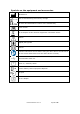
Symbols on the equipment and accessories Manufacturer YYYY-MM Date of manufacturing and country of origin CE mark with identification number of the notified body Serial number Do not dispose of this electrical equipment in domestic waste! Caution Applied part type BF Class II Read the instructions for use before using the Acure device and whenever you are unsure about how to use the Acure device correctly. USB connection. Attention: put the USB cover cap back on the USB connector after each use.
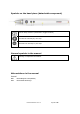
Symbols on the hand piece (detachable component) Start or Stop of action (combined in toggle function) Increase the intensity by one step Decrease the intensity by one step General symbols in the manual Warning or important information. Abbreviations in the manual General EMC ElectroMagnetic Compatibility ESD ElectroStatic Discharge ELST026-AUM001-V0.6.
Table of Contents 1 Safety.............................................................................................................9 1.1 1.1.1 Intended use ....................................................................................................................9 1.1.2 Principle of Operation ...................................................................................................10 1.2 3 4 Safety instructions .................................................................
4.1.1.1 Performing the 4.1.1.2 Option pane buttons in a therapy screen ......................................... 25 4.1.1.3 Show the applied treatment in a graphical representation 4.1.1.4 Close and possibly save the performed treatment application 4.1.1.5 Continue the treatment session with a next sequence 4.1.1.6 Choosing another treatment application in the left menu pane before closing the session ............................................................................... 27 4.1.
4.6.2 Load an existing therapy application via the patient database 4.6.3 Create a new therapy application via the patient database 4.6.4 Reselect an earlier saved treatment session via the patient database 4.7 System settings 4.7.1 5 ....42 ........................................................................................ 43 System settings description .......................................................................................43 Inspections.....................................
7.6 8 APPENDICES ................................................................................................. 59 8.1 EMC directive ...................................................................................................... 59 8.1.1 FCC and IC statement ...............................................................................................59 8.1.2 Guidance and declarations ..........................................................................................60 8.
1 SAFETY 1.1 General 1.1.1 Intended use The gymna Acure device series is intended for the application of Percutaneous Electrolysis, a progressive application technique in the field of electrotherapy. A galvanic current is applied to the patient by the use of an acupuncture needle electrode, functioning as the cathode (negative electrode) in the electrical circuit.
1.1.2 Principle of Operation The device consists of a table top control unit with a mains powered external D.C. power supply, a hand piece to manipulate the needle and a return electrode. The control unit contains a battery to allow operation without external power supply. The power supply is medical grade so it can remain connected during a treatment. It is used to charge the battery and to operate the device, e.g. when the battery is low.
1.2 Safety instructions 1.2.1 General Only qualified people who are trained in the application of the therapy may use the device. For optimum treatment, an anamnesis must first be performed. Based on the findings, a treatment plan with objectives will be formulated. Follow the treatment plan during the therapy. This will limit possible risks, related to the treatment, to a minimum. Only treat patients with electrical implants (pacemaker) after obtaining medical advice.
1.2.4 Electromagnetic compatibility Medical electrical equipment requires special precautions for Electro Magnetic Compatibility (EMC). Follow the instructions for the installation of the equipment. See § 2 Electromagnetic disturbances may cause instability in the output current causing it to exceed the specified tolerances. See the EMC guidance in § 8.1.1 for detailed information.
1.3 Contraindications Treatments should not be given to patients with the listed conditions: 1.3.
1.3.
2 INSTALLATION 2.1 Receipt Procedure 1. Check that the equipment did not get damaged during transport. 2. Check that the accessories are intact and complete. See § 7.6 3. Inform your supplier of any damage or defects by no later than within 3 working days after receipt. Report the damage by telephone, fax, e-mail or letter. Warning: Do not use the equipment if it is damaged or defective. 2.2 Placement of the device Procedure 1. Place the equipment on a horizontal and stable base.
There’s an extra indicator LED, near the Power On button at the backside of the device, if for some reason the condition of the battery is not visible on the LCD. No light White full Green glowing Green full Orange full Device Device Device Device Device is powered Off is powered On. But not connected to the mains power battery is charging battery is fully charged 100% battery level is < 10% Attention: It is recommended to power the device by the supply mains whenever possible.
3 DESCRIPTION OF THE EQUIPMENT 3.
3.2 Components of the Acure device series Front view: 1. full colour 7 inch display with capacitive touchscreen 1 Lift side: (no connections) Right side: 2. connection for the hand piece cable 3. 4 mm banana plug for the 1-pole patient cable (rubber electrode, sponge) 23 Backside: 4. Power-on device switch. 5. LED indicator. Shows the Power conditions, valuable when the device display is not light up. See § 2.4 6. Inlet connector for external medical grade power supply 8 9 4 /5 6 7 7.
Hand piece: (detachable component) 13. Acupuncture needle entrance. See § 7.3 for specifications of the allowed needles 14. Needle fixation/release mechanism knob 15. Multi-colour ring indicating the current state of the device. See § 4.4 16. Start/stop button to perform the treatment 17. button to increase intensity 18. button to decrease intensity 19. Hand piece cable 20 20. Handpiece connector with a lock/unlock function a. red marker must be at the top side a. b.
3.4 Display layout The display is divided in three vertical panes left: the menu pane contains the direct application buttons, the patient database entry, etc. press the desired button to make the selection; scroll vertically for more choices the selected button is indicated in full-colour with a pointer menu pane buttons enabled selected functionality Direct treatment application. Will run in µA-level according corresponding parameters.See §4.1.1, §4.1.2. For parameter ranges see § 7.2.
right: the option pane contains the battery level and shows if the device is connected to the supply mains. This information is kept visible at the top of the option pane. contains supporting buttons related to the choice made on the left side in the menu pane. in this example all related to the µA choice; press the desired button to make the selection; scroll vertically for more choices the selected button is indicated in full white-colour with a pointer.
4 OPERATION Attention: The treatment applications and pre-configured settings are suggestions based on the experiences of medical experts or physiotherapists. They are indicative and can be used as an example, but can also be adjusted to one’s own expertise. This is at the risk of the operator! 4.1 Therapy selection via therapy buttons 4.1.
4. the treatment time in minutes: seconds push on the enabled and buttons to change the timer settings keep the button pressed to change parameter with higher velocity 5. Pushbutton to confirm the correctness of the pre-adjusted parameters therapy output window: (still zero values because treatment is not started yet) 6. the effective treatment time in minutes:seconds 7. the administered electrical charge Q in milli-Coulomb (mC) 4.1.1.
4. From now on are the and buttons on both the hand piece and display enabled to adjust the intensity. 5. Every single push on the or changes the intensity by one step, and is made visible on the hand piece by a short blinking of the green illuminated ring. The output window and value bars: 1. The intensity value bar shows the actual intensity value as a percentage of the maximum allowed intensity value. (e.g. 300/2500) 2.
4.1.1.2 Option pane buttons in a therapy screen Enabled selected functionality Therapy screen is in standard modes in traditional parameter design. See § 4.1.1 and § 4.1.3.1 and § 4.1.4.1 Specific behaviour: The intensity starts from 0 and there’s no preset intensity value target. The intensity must be increased manual with the creases the intensity only one stepsize. button. For every press in- Press button to decrease the intensity with one stepsize.
4.1.1.4 Close and possibly save the performed treatment application Attention: Only when this finished treatment session is linked to a selected patient from the patient database it can be saved to the selected patient. The patient identity is visible in the left upper corner. See §4.6 for the behavior of the patient database. Procedure if a patient is selected: 1. Once the treatment is finished or stopped is it possible to store the applied therapy under the selected patient. 2.
The benefit is that in just one saving action, all individual sequences gets saved. Attention: The next sequence button is not shown if the user has deactivated the use of the “Patient database” in the System settings. 4.1.1.
4.1.2 Therapy selected in µA- level and in advanced modes In the option pane is already chosen for advanced modes (=dashboard parameter design) Specific behaviour in advanced modes: The treatment intensity will increase (fade-in) automatic to the preset intensity value according to a chosen ramp curve once the start button on the hand piece is pressed. explanation of the central pane: 1 2 6 a b 4 c 7 3 5 1. therapy name or application name 2.
adjustable parameters: 3. the intensity circle shows the desired preset intensity value in the middle. The circle contains extra petals to get direct access to the other important parameters and shows the default values directly in the petals. Press a petal and make the desired readjustment. Screen part closes automatic and new value is shown in the petal. For the ranges see §7.2.3 The petal will open as follows: a. Step size settings b. Ramp curve settings slow - medium - fast c.
4.1.2.1 Performing the therapy in advanced modes Beneath describes the necessary actions that need to be taken in correct order on both the device and the hand piece to allow performing the treatment application. For the visual colour feedback of the illuminated ring on the hand piece see § 4.4 Set a therapy Procedure: 1. Press on the corresponding petal to get direct access for changing the parameter values of: a. Intensity step size b. Ramp curve c. Preset intensity as the target value 2.
5. Every single trigger on the and intensity buttons is noticeable via a short blinking of the green illuminated ring. The output window and value bars: 6. The intensity value bar in a circle shows the actual intensity value as a percentage of the maximum allowed intensity value. (e.g. 550/2500) 7. During the therapy increases the effective treatment timer every second while the initial preset treatment timer stays unaltered. 8.
Other option pane buttons in the advanced therapy screen The behaviour of these buttons is exactly the same as for the standard therapy screen Show the applied treatment in a graphical representation See § 4.1.1.3 Further continue the treatment session with a next sequence See § 4.1.1.5 Save and close the performed treatment application See § 4.1.1.4 4.1.3 Treatment applications in mA –range 4.1.3.
4.1.4.2 Performing the therapy in advanced modes The behaviour for trigger points is mainly the same as explained for µA-level. See § 4.1.2 The main differences are: the set Intensity range limit the detection on a closed patient circuit is inactive while performing trigger points! there is no ramp curve setting there is no calculation of the administered electrical charge Q See § 7.2.3 for all different parameter settings. 4.
4.2.1 Therapy selection via Body Area 4.2.1.1 Load a protocol with preconfigured settings via Body area Procedure 1. Press the Body Area button 2. Press the dot corresponding to the anatomical location you want to choose an application from 3. In the example on the right side is already chosen for an existing treatment application at the Shoulder 4. Press the load button to open the corresponding parameter screen with the preconfigured settings 5. From here on the treatment can be applied 4.2.1.
4.2.2 Anatomical library The library contains anatomical images and clinical information of the musculoskeletal system. You can’t access the library during the time that the treatment is applied. Procedure 1. Press the Anatomical library button in the menu pane 2. Select the body part you want to display information of and choose an item from the list if necessary scroll vertically in the list or follow the on screen options to select the desired item 3. The anatomical information is displayed 4.2.
4.3 Placing and connecting the accessories warning: Be sure that before you start treatments you completely understand everything explained in § 1.1.1 Make always use of an echography-imaging device to identify the injury and to define the precise location of the pathologic area. Disinfect the skin surface at the pathologic area. Once the treatment location is defined you need to place the surface electrode & sponge as close as possible to the pathologic zone.
4.4 The coloured illuminated ring on the hand piece The illuminated rings on the hand piece provides the following information. The colours can be green (normal operation), orange (point to be attentive), red (warning) which points that an immediate response of the operator is required.
4.5 Patient circuit not closed detection There is an integrated detection to monitor if the electrical patient circuit is closed during the application. The detection will work over de whole amplitude range in both µA-level and in mA-level. This detection is not activated for trigger point applications. The user will be warned auditory and visually via a warning message on the display and a colour change of the illuminated ring in the hand piece. audio: see § 4.7.
4.6 Patient database 4.6.1 Administer the Patient database This menu allows to administer the patient database. Only via the patient database it is possibility to store, reopen or manage performed treatment applications which are directly linked to the patient. Attention: If you do not want to make use of the benefits of the Patient database you can hide the patient database button in the menu pane. Go to System settings menu and change the parameter; Patient database use to Off-mode See § 4.7.
4.6.2 Load an existing therapy application via the patient database Procedure 6. Press the Patient database button in the menu pane 7. The patient list appears in alphabetic order if necessary scroll vertically in the list or perform a search to find the name 8. Select the desired patient 9. Select the load button to choose a therapy application for the selected patient 10. A new screen appears from which you can select a new therapy application for the selected patient 11.
4.6.3 Create a new therapy application via the patient database Procedure 11. Perform the same steps 1 until 6 as explained in the above § 4.6.2 12. Make a selection via the Body area entry and choose the desired location. (e.g. shoulder) 13. When the list does not contain yet the desired treatment application it is possible to create a new one. 14. Select the new button to create a new application 15. Enter a name for the new treatment application 16. Make the desired parameter settings 17.
4.6.4 Reselect an earlier saved treatment session via the patient database Procedure 1. Press the Patient database button in the menu pane 2. The patient list appears in alphabetic order if necessary scroll vertically in the list or perform a search to find the name 3. Select the desired patient 4. Press the Sessions button 5. A new screen appears showing all saved sessions of the selected patient with the most recent on top 6. Select the desired session 7.
4.7 System settings With the system settings, you can adapt the default factory settings or actual stored settings of the equipment. You can not change the system settings during the running of a therapy. Procedure 1. Press the System settings button in the menu pane 2. Select the desired system setting in the detail pane if necessary scroll vertically in the list or follow the on screen options to select or re-adjust the setting screen layout of individual setting can differ somehow 4.7.
Sound: Activate or deactivate the sound settings for specific situations. they function as audio feedback to be attentive or as a warning. they are not meant to function as alarm signals! Parameter range Volume 1 ..
Procedure to check the coloured illuminated ring 1. Select: Illuminated ring test 2. Follow the on screen instructions 3. The guided hand piece picture shows directly the corresponding result of the test activity Rubber electrode test: With this test is the condition of the silicone rubber electrode tested. Follow the on screen instructions to perform the test. Error history: view the total number of errors and details about the last 10 errors reported.
5 INSPECTIONS AND MAINTENANCE 5.1 Inspections Component Check Frequency hand piece: cable, connector ‘damage’ insulation intact PINS in connector at least 1x per month hand piece: buttons & coloured Illuminated ring ‘functionality’ see § 4.7.1 at least 1x per month electrode cable & rubber electrode ‘damage’ insulation intact at least 1x per month electrode cable & rubber electrode ‘conductivity’ see § 4.7.1 at least 1x per month main device ‘technical safety inspection’ see § 5.1.1, § 8.
Inspection result 1. A registration must be maintained of the technical safety inspections. Use the inspection report in the appendix for this purpose. See § 8.2 2. Copy this appendix. 3. Complete the copied appendix. 4. Keep the inspection reports for at least 10 years. The inspection is successful if all inspection items are passed. Repair all faults on the equipment before the equipment is put back into operation.
5.2.1 Cleaning the main unit Caution: Do not sterilize the unit Do not use chloride based agents as these may affect the casing parts of the device General cleaning: 1. Remove dust with a soft micro fiber cloth 2. If necessary, remove stains or dirt with a damp micro fiber cloth 3. If required, clean the device with a small amount of mild household detergent Surface disinfection: 4.
5.2.3 Cleaning the hand piece and patient cable Surface disinfection: 1. Remove the acupuncture needle and be careful to dispose the needle safely. 2. Avoid that any liquid directly enters into the needle holder. Therefore, do not immerse the front side of the needle holder neither the cable connectors into any cleaning or disinfecting liquids. 3. Disinfect the hand piece and cables with a 70% alcohol solution. 4.
6 MALFUNCTIONS, SERVICE AND WARRANTY 6.1 Malfunctions Component Problem Solution Device Device cannot be switched on See § 6.1.1 Device does not react to commands or a fault report appears See § 6.1.2 Device does not react to triggers performed on the hand piece sponges See § 6.1.3 Foreign language on the screen Change the language. See § 4.7.1 Furring Replace the sponges Bad conduction Replace the sponges 6.1.1 Device cannot be switched on Procedure 1.
3. Contact your dealer if the hand piece malfunctions 6.2 Service Caution: Only a technician authorised by GymnaUniphy N.V. may open the equipment or the accessories to perform repairs. The equipment does not contain any components that may be replaced by the user. If possible, open the screen with the system settings before you contact the technical service department. See § 4.7.1 Service and warranty are provided by your local GymnaUniphy dealer.
6.4 Technical lifespan The expected lifespan of the device is 6 years counting from the production date. Please refer to the identification plate. GymnaUniphy N.V. will provide service, spare parts and accessories for 6 years after the production date except in case of force majeure. ELST026-AUM001-V0.6.
7 TECHNICAL DATA 7.1 General Dimensions Unit (wxdxh) 210 x 160 x 90 mm Weight ~ 0,85 kg Weight incl. accessories ~ 1,00 kg Supply voltage 12 VDC Maximum currrent rating 2A Class Electrical class II Dimensions hand piece (wxdxh) 175 x 16 x 16 mm Weight hand piece ~ 0,060 kg Weight power supply ~ 0,17 kg Mains voltage 100-240 V, 50-60 Hz Current rating 0.6 A - 0.3 A Maximum power rating 24 W Operation mode suited for continuous operation 7.
7.2.2 Bluetooth Operating frequency band 2402-2480 MHz Receiving bandwidth 2402-2480 MHz Modulation GFSK Effective radiated power 0.066W ELST026-AUM001-V0.6.
7.2.3 Parameter properties Intensities and time: Therapy method Treatment time 02:00 min Intensity step sizes 50- 100- 250- 500 Preset intensities in advanced modes 300- 500- 1000- 2000 Intensity maximum range 2500 (µA) (µA) (µA) 0.5 - 1.0 2.0- 3.0- 4.0 – 6.0 8.0 (mA) (mA) (mA) 0.5 0.5- 1.0 1.
7.3 Acupuncture needle Attention: We recommend to purchase the acupuncture needles from a local distributor, who strictly complies according the applicable local legislation. Immediately remove and dispose the acupuncture needle after use in a safe way. Place the hand piece always in the holder without needle when it is not used. 7.3.
7.4 Environmental conditions Ambient temperature +10 °C to + 35 °C Relative humidity 30% to 75% Atmospheric pressure 70 kPa to 106 kPa 7.5 Transport and storage Transport weight device ~1,00 kg Storage and transport temperature -40 °C to +60 °C Relative humidity 10% to 100%, including condensation Atmospheric pressure 20 kPa to 106 kPa Transport classification Single piece, by post The transport and storage specifications apply to equipment in the original packaging. ELST026-AUM001-V0.6.
7.6 List of standard and optional accessories Check for the article numbers in the most recent datasheet or ask your local dealer. Description Quantity Standard Optional external medical grade power supply; cable length 1.50 m 1 S set of power adaptor sockets for other EU countries 1 S rechargeable battery pack 7,4V 5200mAh (li-ion) 1 S Handpiece ; cable length 2.10m 1 S hand piece holder 1 S 1-pole patient cable; 4mm M to 2 mm F; cable length 2.
8 APPENDICES 8.1 EMC directive Use only cables, electrodes and hand pieces that are specified in this manual. See § 7.6 The use of other accessories can have a negative effect on the electromagnetic compatibility of the equipment. If you use the Acure device in the vicinity of other equipment, you must check that the device is functioning normally. The following paragraphs contain information about the EMC properties of the equipment. 8.1.
8.1.2 Guidance and declarations Guidance and manufacturer’s declaration - electromagnetic emissions The Acure device is intended for use in the electromagnetic environment specified below. The customer or the user of a Acure device should assure that it is used in such an environment. Emission test Compliance Electromagnetic environment - Guidance RF emissions CISPR 11 Group 1 The device use RF energy only for their internal function.
Guidance and manufacturer’s declaration - electromagnetic immunity The Acure device is intended for use in the electromagnetic environment specified below. The customer or the user of a Acure device should assure that it is used in such an environment.
NOTE: UT is the a.c. mains voltage prior to application of the test level Guidance and manufacturer’s declaration - electromagnetic immunity The Acure device is intended for use in the electromagnetic environment specified below. The customer or the user of a Acure device should assure that it is used in such an environment.
50.0-54.0 MHz Radiated RF IEC 61000-4-3 AM 10 V/m 0.08-2.7 GHz 1 kHz/80% 10 V/m 0.082.7 GHz RF proximity fields CW 18 IEC 61000-4-3 Hz/50% 27 V/m 380 – 390 MHz, 28 V/m 800-960 MHz FM 1kHz/±5kHz 28 V/m 430470 MHz CW 217 Hz/50% 9 V/m 704787 MHz, 28 V/m 1.70-1.99 GHz, 28 V/m 2.40-2.57 GHz, 9 V/m 5.10-5.80 GHz d = 0.35√p .... 80 MHz to 800 MHz d = 0.70√p 800 MHz to 2.7 GHz 27 V/m 380 –390 MHz 28 V/m 430-470 MHz d = 0.22√p ............ 380–390 MHz d = 0.22√p ............
8.2 Technical safety inspection device with serial number ............. is / is not4 in good working order Inspection performed by: Owner: Location: Name: Name: Date: Initials: Initials: 4 Cross out what does not apply. If a specific test does not apply to this equipment, place a mark in the NA (not applicable) column. 8.2.1 Test 1: General Yes 1. The results of earlier safety inspections are available. 2. The logbook is present. 3. The type plate and the supplier’s label are legible. 4.
8.2.2 Test 2: Patient circuit 1. Connect a load of 1000 Ω between the hand piece needle entry and the 1-pole patient cable. Connect an oscilloscope to the 1000 Ω load. (Needle side is the negative pole) 2. Select current in mA-level and adjust to maximum intensity. 3. At maximum intensity, the output currents corresponds within 10% with the values on the display. 4. The output signals correspond with Figure 1. 5. The warning ‘Patient circuit is not closed’ is given if the load is disconnected.
8.2.4 Test 4: Electrical safety test (IEC 62353) Yes 1 The touch current is less than 1000 µA 2. The patient leakage current is less than 5000 µA No Notes: _____________________________________________________________________ _____________________________________________________________________ _____________________________________________________________________ _____________________________________________________________________ 8.2.
8.3 Decommissioning 8.3.1 Disposal Take account of the following environmental aspects when disposing of the equipment and the accessories: The power supply, main device, hand piece, the cables and the electrodes are waste electrical and electronic equipment. They components contain tin, copper, iron, various other metals and various plastics, etc. Dispose of them according to national regulations. The device contains a battery-pack.
Gymna Pasweg 6A B-3740 Bilzen Tel.: (+32) (0) 89/510.532 Fax: (+32) (0) 89/510.541 www.gymna.com info@gymna.com Your dealer: ELST026-AUM001-V0.6.