FR 2-9 / 10-31 / 98-108 EN 2-9 / 32-54 / 98-108 GYSPOT PTI-s7 400 V DE 2-9 / 55-75 / 98-108 ES 2-9 / 76-97 / 98-108 73502_V4_21/07/2022 www.gys.
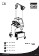
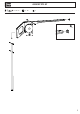
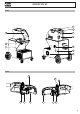
GYSPOT PTI S7 MONTAGE SUPPORT / ASSEMBLY OF SUPPORT / MONTAGE HALTERUNG / MONTAJE DEL SOPORTE M6x16 (x4) 10 N·m M6x16 (x4) 10 N·m MONTAGE SUPPORT CÂBLE/ CABLE SUPPORT ASSEMBLY / MONTAGE DER KABELHALTERUNG / MONTAJE DEL SOPORTE DEL CABLE M5x12 (x2) 6 N·m PE OTY T PRO M5x20 (x6) 2 6 N·m
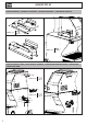
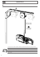
GYSPOT PTI S7 FR MONTAGE SUPPORT BRAS / ASSEMBLY OF ARM SUPPORT / MONTAGE ARM / MONTAJE DEL SOPORTE PARA BRAZO M5x12 (x4) 6 N·m PE OTY T PRO 3
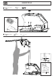
GYSPOT PTI S7 MONTAGE POTENCE / ASSEMBLY OF OVERHANGING ARM / MONTAGE AUSLEGER / MONTAJE DEL SOPORTE GRÚA 1 | A: x2 : M6 x16 B: x2 : M6 x2 : M8 x 25 B C B A A 2| 4 x1 : M6 x16 x1 : M6 x2 : M8 x 25 C: x1 : M8 x16
GYSPOT PTI S7 3| x3 : M8 x 60 x3 : M8 x1 5
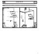
GYSPOT PTI S7 4| 250 cm max. 99 inch max. 14 kg max. 31 lb max. Pour régler la tension du câble de l’équilibreur, l’utilisateur doit impérativement mettre la pince en charge sur le câble. To adjust the tension of the cable in the pulley system, the user must place the clamp on the cable. Einstellung des Federzugbalancers immer unter Last! Zuvor Zange einhängen! Para ajustar la tensión del cable del equilibrador, el usuario debe imperativamente colocar la pinza en carga sobre el cable.
GYSPOT PTI S7 5| x2 : M8 x 20 6| x2 : M8 x 20 x1 x1 x1 x1 x2 M8x20 20 N·m 7
GYSPOT PTI S7 7| 8
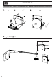
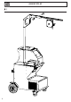
GYSPOT PTI S7 FIG-1 4 8 2 7 5 1 9 3 10 6 FIG-2 2 8 3 4 5 6 1 9 7 9
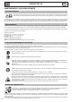
GYSPOT PTI S7 FR AVERTISSEMENTS - RÈGLES DE SÉCURITÉ CONSIGNE GÉNÉRALE Ces instructions doivent être lues et bien comprises avant toute opération. Toute modification ou maintenance non indiquée dans le manuel ne doit pas être entreprise. Veiller à bien conserver ce manuel d’instruction pour des consultations ultérieures. Tout dommage corporel ou matériel dû à une utilisation non-conforme aux instructions de ce manuel ne pourra être retenu à la charge du fabricant.
GYSPOT PTI S7 FR • Cet équipement de soudage produit des fumées et des gaz qui contiennent des produits chimiques dont l’État de Californie reconnait qu’ils provoquent des malformations congénitales et, dans certains cas, des cancers (code de santé et sécurité de Californie, chapitre 25249.5 et suivants).
GYSPOT PTI S7 FR RECOMMANDATIONS POUR ÉVALUER LA ZONE ET L’INSTALLATION DE SOUDAGE Généralités L’utilisateur est responsable de l’installation et de l’utilisation du matériel de soudage par résistance suivant les instructions du fabricant. Si des perturbations électromagnétiques sont détectées, il doit être de la responsabilité de l’utilisateur du matériel de soudage par résistance de résoudre la situation avec l’assistance technique du fabricant.
FR GYSPOT PTI S7 INSTALLATION DU MATÉRIEL • Mettre la source de courant de soudage sur un sol dont l’inclinaison maximum est de 10°. • La source de courant de soudage doit être à l’abri de la pluie battante et ne pas être exposée aux rayons du soleil. • Le matériel est de degré de protection IP20, signifiant : - une protection contre l’accès aux parties dangereuses des corps solides de diam >12.5 mm et, - aucune protection contre les projections d’eau.
FR GYSPOT PTI S7 INSTALLATION – FONCTIONNEMENT PRODUIT Seul le personnel expérimenté et habilité par le fabricant peut effectuer l’installation. Pendant l’installation, s’assurer que le générateur est déconnecté du réseau. Les connexions en série ou en parallèle de générateurs sont interdites.
FR GYSPOT PTI S7 ACCESSOIRES ET OPTIONS Liquide de refroidissement 40 caps x 10 x 18 x 18 Housse de protection Carte SD avec programmes Equilibreur 10>14 kg 050914 059696 x6 5 l : 062511 10 l : 052246 048935 050068 050853 Affûteur de caps Capteur d’effort Valise de test de soudure Europax anti-corrosion Kit pistolet 048966 052314 050433 052758 067318 67 67 200 mm 97 167 mm 30 C1 8 bar/550 daN C12 8 bar/550 daN 022997 C5 8 bar/550 daN 89 165 mm 44 C2 C3 C4 + + C2 C3 C4
FR GYSPOT PTI S7 REMPLISSAGE DU RÉSERVOIR DE LIQUIDE DE REFROIDISSEMENT Le liquide de refroidissement recommandé par GYS, doit impérativement être utilisé : 5 l : ref. 062511 • 10 l : ref. 052246 L’utilisation de liquides de refroidissement autres, et en particulier du liquide standard automobile, peut conduire, par un phénomène d’électrolyse, à l’accumulation de dépôts solides dans le circuit de refroidissement, dégradant ainsi le refroidissement, et pouvant aller jusqu’à l’obstruction du circuit.
GYSPOT PTI S7 2 Enregistrement d’un rapport FR 5 Réglage de l’épaisseur de tôle Cette fonctionnalité est détaillée dans le chapitre correspondant. La touche permet d’activer ou non l’écriture d’un rapport. La touche permet de visualiser la série de points effectuée. La valeur de ce réglage correspond l’épaisseur des tôles à souder. Le choix de l’épaisseur se fait par les touches + et -, les épaisseurs disponibles sont 0.6, 0.8, 1.0, 1.2, 1.5, 1.8, 2.0, 2.5 et 3.0 mm.
GYSPOT PTI S7 Mode AUTO FR Ce mode s’affiche par défaut au démarrage de la machine. Ce mode permet de souder les tôles sans spécifier aucun paramètre à l’écran de la machine. Celle-ci détermine elle-même les paramètres de soudage adaptés. Pour pouvoir utiliser ce mode, effectuer au préalable un point à vide (sans tôles entre les électrodes), comme demandé à l’écran. Presser le bouton. Le message « Effectuer un point à vide » apparait à l’écran. Presser à nouveau le bouton pour effectuer la calibration.
GYSPOT PTI S7 Mode GYSTEEL FR Le mode GYSTEEL est optionnel; il est configurable dans le menu « Réglages ». Ce mode est identique au mode normal sauf que l’utilisateur saisit la limite élastique des tôles (Re). Cette valeur «Re» peut être connue en utilisant un duromètre tel que le GYSTEEL Vision. Re Re Re Re : : : : 1-10 correspond aux aciers doux. 11-18 correspond aux aciers HLE/THLE. 19-35 correspond aux aciers UHLE. 36-99 correspond aux aciers au bore.
GYSPOT PTI S7 FR Contrôle daN : Ce réglage permet d’activer ou de contrôler l’effort de serrage de la pince lors d’une soudure. Mode COLLE : Sur l’écran RÉGLAGES ci-dessus, l’utilisateur peut préciser la présence de colle entre les tôles. Si le mode colle est activé, un prépoint est réalisé avant le point de soudure. La durée de ce prépoint est paramétrée en millisecondes, de 0 à 400 ms, par palier de 50 ms.
GYSPOT PTI S7 FR En mode Normal, le pistolet sera limité à des tôles de 1.5 mm maximum. Avec le pistolet, l’opérateur a le choix entre différents outils (mono point, étoile, impact, chauffe rétreinte, goujon, rivet, écrou, molette). La sélection de l’outil se fait avec les touches + et -. En mode Manuel, l’intensité maximale admise sera de 8 kA pendant une durée qui ne pourra pas excéder 500 ms. Les réglages à l’écran seront donc bloqués à ces valeurs maximum.
GYSPOT PTI S7 FR Courant trop faible 1/ Vérifier ligne Si le courant obtenu pendant le point est inférieur à la valeur de consigne (6 %), la machine indique une fois le point effectué un message d’avertissement « Courant faible, vérifier ligne » indiquant que le point est à vérifier. 2/ Vérifier tôles Si la machine ne peut pas obtenir le courant demandé alors le message d’erreur « Courant faible, vérifier tôles » s’affiche. Le point n’est pas effectué et le défaut doit être acquitté pour faire un point.
FR GYSPOT PTI S7 La saisie de l’identifiant se fait avec les 4 touches +, ou . Lors de la saisie d’un identifiant déjà utilisé, la machine enregistrera les nouveaux points à la suite, sans effacer les précédents. La touche permet de récupérer un rapport précédemment enregistré et de le relire sur l’écran. Il faut arrêter l’enregistrement en cours en appuyant sur la touche mode visualisation du rapport. Pour effacer le contenu d’un rapport, il faut l’afficher sur l’écran en utilisant la touche .
FR GYSPOT PTI S7 Les touches de déplacement ( ou ) permettent de changer les lettres ou chiffres. Les touches – et + permettent de déplacer le curseur dans le champ. L’appui court sur la touche champs pour la modification ou la lecture. permet d’effacer le champ. La touche permet le défilement des Catalogue La touche maxi) permet la consultation des ordres de réparation. Le numéro de page est affiché (13 Les touches – et + permettent de changer de page. Les touches ner le Job suivant ou précédent.
GYSPOT PTI S7 FR MONTAGE ET CHANGEMENT DES BRAS DE LA PINCE Veuillez lire attentivement les consignes qui suivent. Un mauvais serrage ou réglage des bras de la pince en C peut entraîner une surchauffe importante du bras et de la pince et les détériorer de manière irrémédiable. Les anomalies dues à un mauvais montage ne sont pas couvertes par la garantie. -M ettre la machine hors tension, en coupant le disjoncteur ou choisir le mode « réglage pince ».
GYSPOT PTI S7 FR RÉGLAGE DES BRAS DE LA PINCE 1 - Baisser le bouton de blocage 1 qui permet la sur ouverture - Tirer la molette de réglage 2 et la tourner pour qu’elle pose sur la goupille 3 . - Serrer la bague crantée 4 à la main puis tourner la molette de réglage 2 pour qu’elle retourne dans son logement et empêche la bague crantée de tourner. 3 4 2 - Serrer le levier à la main, et vérifier qu’il n’est pas en butée contre sa fin de course.
GYSPOT PTI S7 FR CONTRÔLE PÉRIODIQUE DE LA PINCE Le serrage des vis suivantes doit être contrôlé périodiquement (tous les mois) : Vis fixant le support de bras sur le corps de la pince : Ces 4 vis assurent la fixation du support de bras sur le corps de la pince ; leur bon serrage garantit une bonne transmission du courant de soudage. Un mauvais serrage entraine une perte de courant de soudage, et au pire peut endommager de manière irréversible le support de bras ou le corps de la pince.
FR GYSPOT PTI S7 LOGICIEL GYSPOT SUR PC Ce logiciel à pour objectif d’éditer et de sauvegarder les rapports de points réalisés à l’aide d’un GYSPOT équipé d’un lecteur de carte SD. Pour utiliser ce logiciel, le PC doit être équipé d’un lecteur de carte SD. Le logiciel GYSPOT peut être installé à partir de fichiers présents sur la carte SD. Dans le répertoire \GYSPOT V X.XX , double cliquer sur le fichier INSTALL.EXE, et suivre les instructions pour installer le logiciel sur votre PC.
GYSPOT PTI S7 FR 4 - Paramétrage de points Pour passer en mode « Paramétrage de points », cliquer sur Paramétrage de points dans le menu Options. Le mode « Paramétrage de point » permet de proposer à l’utilisateur des points paramétrés par les constructeurs. Ce mode permet aussi à l’utilisateur de configurer ses propres paramètres de soudure.
FR GYSPOT PTI S7 4.4 - Supprimer un point paramétré dans le fichier USER : Sélectionner un point paramétré dans la liste puis cliquez sur le bouton Intervenant : Raison sociale : JBDC Téléphone : 0243510101 Adresse : ZI, 134 Bd des Loges Télécopie : 0243510102 Email : contact@companyname.com Site Web : www.companyname.com Code postal : 53941 Ville : Saint-Berthevin OPERATEUR Ordre de réparation : Date du journal : 977AC92 05/04/2018 Intervention : Commentaires : à droite de la liste.
FR GYSPOT PTI S7 Pistolet Echauffement anormal du pistolet Manque de puissance avec le pistolet Mauvais serrage du mandrin. Vérifier le serrage du mandrin, du mandrin porte-étoiles, et l’état de la gaine. Gaine pistolet déchaussée. Replacer la gaine pour que le refroidissement air parvienne à l’intérieur du pistolet Mauvais positionnement du patin de masse. Vérifier que le patin de masse est en contact avec la bonne tôle Mauvais contact du patin de masse.
GYSPOT PTI S7 EN WARNING - SAFETY RULES GENERAL INSTRUCTIONS Read and understand the following safety instructions before use. Any modification or updates that are not specified in the instructions manual should not be undertaken. Please store this manual safely. The manufacturer is not liable for any injury or damage due to a non-compliance with the instructions featured in this manual. In the event of problems or uncertainties, please consult a qualified person to handle the installation properly.
GYSPOT PTI S7 EN • This welding equipment produces fumes and gases that contain chemicals considered by the State of California as a source of congenital malformations and potentially, cancers (refer to the California Health Code, chapter 25249.5 and after). • This equipment contains chemicas, including lead, identified by the state if California as a potential cause of cancers and congenital malformations or other issues in relation to procreation. Wash your hands after handling.
GYSPOT PTI S7 EN RECOMMENDATIONS FOR WELDING AREA ASSESSMENT AND WELDING Miscellaneous The user is responsible for the correct installation and usage of the welding material based on the instructions supplied by the manufacturer. If electromagnetic disturbances are detected, it is the user’s responsibility to resolve the situation with the manufacturer’s technical assistance. In some cases, this corrective action may be as simple as earthing the welding circuit.
EN GYSPOT PTI S7 MAINTENANCE / RECOMMENDATIONS • The operators must have received suitable training in order to use the machine at its maximum potential and weld correctly. • Check which welding process is authorised by the manufacturer before attempting any vehicle repair. The maintenance and repair of the machine can only be undertaken by the manufacturer. Any work undertaken by a third party on the machine will invalidate the warranty.
EN GYSPOT PTI S7 INSTALLATION – PRODUCT OPERATION Only qualified personnel authorised by the manufacturer should perform the installation of the welding equipment. During the installation, the operator must ensure that the machine is disconnected from the mains. Connecting generators in serial or in parallel is forbidden.
EN GYSPOT PTI S7 ACCESSORIES AND OPTIONS Coolant 40 caps x 10 x 18 x 18 Protective cover SD card including automatic programs Overhanging balancing system 10>14 kg 050914 059696 x6 5 l: 062511 10 l: 052246 048935 050068 050853 Caps sharpener Pressure sensor Welding test case Europax anti-corrosion Gun kit 048966 052314 050433 052758 067318 67 67 200 mm 97 167 mm 30 C1 8 bar/550 daN C12 8 bar/550 daN 022997 C5 8 bar/550 daN 89 165 mm 44 C2 C3 C4 + + C2 C3 C4 + + C2 C
EN GYSPOT PTI S7 REFILL OF THE COOLING LIQUID TANK The cooling liquid recommended by GYS must be used: 5 l: ref. 062511 • 10 l : ref. 052246 The use of other cooling liquids, especially standard automotive liquid, can lead, through electrolysis, to the accumulation of solid deposits in the cooling system, reducing the cooling, and may even lead to system block. Any damage to the machine caused by the use of another coolant is excluded from the warranty.
GYSPOT PTI S7 2 Saving a report EN 5 Setting the thickness of the plate This function is detailed in the corresponding chapter. Button activates or deactivates the creation of a report. Button is used to view the points completed. 3 Using the different modes The value to be entered is in relation to the thickness of the sheets being welded on. The selection of the thickness is done using the + and - buttons, the different thicknesses available are 0.6, 0.8, 1.0, 1.2, 1.5, 1.8, 2.0, 2.5 and 3.0 mm.
EN GYSPOT PTI S7 In order to use this mode, do a blank spot weld (without any sheet/panel between the electrodes),as prompted on the display. Push the button. The message «Do a spot without a load» is displayed on the screen. Push the button again to calibrate. Once the calibration is done, the machine shows all the settings to zero, and is ready to weld. Close the clamp on the area to weld and weld automatically, without entering any parameters in the machine.
EN GYSPOT PTI S7 MANUFACTURER mode The MANUFACTURER mode is optional; it can be modified using the « Settings» menu. This mode is used to name a pre-registered spot based on the repair book issued by the manufacturer. Spot welds programmed by the user can be recalled by selecting USER in the manufacturers list. Welding spots can be programmed using the GYSPOT software and the welding spots settings module. Push the button for 2 seconds to return to the AUTO mode.
GYSPOT PTI S7 EN GLUE mode: On the SETTINGS screen below, the user can specify the presence glue between the panels/sheets. When this mode is in use, a pre-spot is performed before the weld. The duration of this pre-spot is set in milliseconds, from 0 to 400 ms, with 50 ms thresholds. When the glue mode is selected, la word « GLUE » is displayed in the menus of the NORMAL, MANUAL, MULTI or GYSTEEL welding modes. USE OF THE GUN (OPTION) - Select the GUN tool using the button .
GYSPOT PTI S7 EN In Manual mode, the maximum possible intensity is 8 kA for a maximum duration of 500 ms. The settings showing on the screen will not exceed these values. Set the generator by indicating the thickness of the sheet/panel to weld using + and - keys. It is possible to adjust the current and time settings when in manual mode. Press the button for 2 seconds to get back to the NORMAL mode. ERROR MANAGEMENT Various elements may produce errors.
EN GYSPOT PTI S7 Insufficient air pressure If the input pressure is insufficient to deliver the tightening requested, the machine beeps and displays, before the weld, the error message «Insufficient air pressure». Pressing the trigger a second time is used to «force» the spot weld using the available pressure. If the tightening recorded is insufficient, the machine displays «Low pressure». «p low» is also recorded in the active report.
EN GYSPOT PTI S7 Identification mode If the identification mode is set to «ON», all mandatory fields in the repair order must be entered to allow the weld to go ahead or the machine will display «identification fault». To activate and deactivate the identification mode, an SD identification card must be inserted in the BP card reader instead of the SD card containing the programs. The settings screen is activated by pressing and holding down the button for 2 seconds.
GYSPOT PTI S7 EN • The SD card management library allows you to manage your SD cards over 2 GB.. • For each repair order, a log file xxx.dat is associated (with xxx=identifier from 001 to 100). In each log, a maximum of 500 welding points can be recorded. On consultation, the names of the repair order and the user are displayed. • The page number is indicated at the top left.. • All repair orders are stored in the file called catalog.GYS.
GYSPOT PTI S7 EN - Disconnect the cooling liquid pipes and unlock the lever. - Remove the clamp arm. - Lubricate both a new arm and the support with contact grease (ref.050440). Specific Installation for C2 and C8 arms For these arms, the Stretches will also need to be changed. Unscrew the short stretches with a flat spanner and remove the injector.
GYSPOT PTI S7 EN - Tighten the lever manually and check it is not end up against the joint stop (see diagram below). If it is the case go back to step previous. OK NOK Warning: Clamp and arm may be damaged if the lever is not tightened properly. - Check the cooling liquid level. - Check screws and lever, incorrectly tightening can damage the material. - Switch on the machine.
GYSPOT PTI S7 EN CONNEXION GYSPOT / C CLAMP : B : Black G : Green W : White Y : Yellow THE GYROSCOPE Fix the gyroscope with 4 screws M5 x 12. It can rotate around the clamp at a 360° angle. GYSPOT SOFTWARE ON PC The purpose of this software is to edit and save the spot weld reports made using a GYSPOT equipped with an SD card reader. To use this software, the PC must be equipped with an SD card reader. The GYSPOT software can be installed from files on the SD card. In the directory \GYSPOT V X.
EN GYSPOT PTI S7 3 - Traceability By default, the GYSPOT software opens in «Traceability» mode. In «Point Setting» mode, click on Traceability in the Options menu. 3.1 - Importing point reports from an SD card : To import the point reports made with a GYSPOT into your PC, insert the SD card into the card reader on your PC and start the GYSPOT software. Then select the reader into which your SD card is inserted and click on the button .
GYSPOT PTI S7 EN Then double-click in the second column to select a manufacturer file previously downloaded from our website. The list of spots set by the manufacturer is displayed in the second list. Select a configured point to view the chronogram and configured parameters. 4.2 - Add a configured spot in the USER file : To add a spot to the USER file, select the USER file from the file list and click on the button to the right of the list of configured spots.
EN GYSPOT PTI S7 SAFETY AND MAINTENANCE User training People operating this machine must receive suitable training in order to get the most out of the machine capabilities and carry out good quality repairs (examples: car body work training). Preparation of the parts to be assembled It is essential to clean and accost the area to be welded. In the case of a protective application, make sure that it is conductive by first testing a sample.
GYSPOT PTI S7 DE SICHERHEITSANWEISUNGEN ALLGEMEIN Lesen Sie vor Inbetriebnahme des Gerätes die Anleitung sorgfältig durch. Nehmen Sie keine Wartungarbeiten oder Veränderungen am Gerät vor, wenn diese nicht explizit in der Anleitung gennant werden. Bewahren sie diese Bedienungsanleitung sorgfältig auf. Der Hersteller haftet nicht für Verletzungen oder Schäden, die durch unsachgemäße Handhabung dieses Gerätes enstanden sind.
GYSPOT PTI S7 DE Achtung! Bei Schweißarbeiten in kleinen Räumen müssen Sicherheitsabstände besonders beachtet werden. Beim Schweißen von Blei, auch in Form von Überzügen, verzinkten Teilen, Kadmium, «kadmierte Schrauben», Beryllium (meist als Legierungsbestandteil, z.B. Beryllium-Kupfer) und andere Metalle entstehen giftige Dämpfe. Erhöhte Vorsicht gilt beim Schweißen von Behältern. Entleeren und reinigen Sie diese zuvor. Um die Bildung von Giftgasen zu vermeiden bzw.
GYSPOT PTI S7 DE Alle Schweißer sollten gemäß dem folgenden Verfahren die Exposition zu elektromagnetischen Feldern aus Schweißgeräten minimieren : • Elektrodenhalter und Massekabel bündeln, wenn möglich machen Sie sie mit Klebeband fest; • Achten Sie darauf, dass ihr Oberkörper und Kopf sich so weit wie möglich von der Schweißarbeit entfernt befinden; • Achten Sie darauf, dass sich die Kabel, den Brenner oder die Masseklemme nicht um Ihren Körper wickeln; • Stehen Sie niemals zwischen Masse- und Brennerk
DE GYSPOT PTI S7 AUFSTELLUNG • Stellen Sie das Gerät ausschließlich auf festen und sicheren Grund, dessen Neigungswinkel nicht größer als 10° ist und sichern Sie es gegen weg rollen. • Schützen Sie das Gerät vor Regen und direkter Sonneneinstrahlung. • Das Gerät ist IP20-Schutzart konform, d.
DE GYSPOT PTI S7 AUFBAU UND FUNKTION Das Gerät darf nur von qualifizierten und befugten Personen montiert und in Betrieb genommen werden. Der Aufbau darf nur im ausgeschalteten, nicht angeschlossenen Zustand vorgenommen werden. Serien- oder Paralellanschlüsse von Generatoren sind untersagt. BESCHREIBUNG (ABB.
DE GYSPOT PTI S7 ZUBEHÖR UND OPTIONEN Kühlmittel 40 Kappen x 10 x 18 x 18 Schutzhaube SD-Karte mit Programmen Federbalancer 10>14 kg 050914 059696 x 6 5 l : 062511 10 l : 052246 048935 050068 050853 Elektrodenkappenschleifer Kraftsensor Schweißtestkoffer Europax Rostschutzpaste Pistolen-Bausatz 048966 052314 050433 052758 067318 67 67 200 mm 97 167 mm 30 C1 8 bar/550 daN C12 8 bar/550 daN 022997 C5 8 bar/550 daN 89 165 mm 44 C2 C3 C4 + + C2 C3 C4 + + C2 C3 C4 01912
DE GYSPOT PTI S7 BEFÜLLUNG DES KÜHLMITTELTANKS Das von GYS empfohlene Kühlmittel muss verwendet werden : 5 l : Art.-Nr. 062511 • 10 l : Art.-Nr. 052246 Die Verwendung anderer Kühlflüssigkeiten, insbesondere von Standardkühlflüssigkeiten, kann wegen der Elektrolyseprozesse zur Bildung von festen Substanzen innerhalb des Kühlkreislaufes führen, die der Effizienz der Kühlung schaden und unter Umständen zum Totalausfall des Systems durch Verstopfen führen können.
GYSPOT PTI S7 2 Speichern von Berichten DE 5 Anzeige Blechstärke Eine ausführliche Beschreibung zu dieser Funktion finden Sie in einem separaten Kapitel dieser Betriebsanleitung. Die «BERICHT» Taste dient zur Aktivierung / Deaktivierung der Berichtsfunktion. Die «ANZEIGE» Taste aktiviert die Anzeige der geschweißten Punktfolge. 3 Nutzung der Modi Die angewählte Stärke der zu schweißenden Bleche wird angezeigt. Die Auswahl erfolgt über die + und - Pfeiltasten innerhalb der voreingestellten Werte 0.
GYSPOT PTI S7 AUTO Modus DE Standardmäßig ist dieser Modus beim Start der Maschine angezeigt. Dieser Modus ermöglicht auf Basis verschiedener Sensoriken das effektive Schweißen unterschiedlichster Blechkombinationen ohne vorherige Einstellung der Parameter an der Maschine. Sie bestimmt selbstständig die geeigneten Schweißparameter. Setzen Sie zuerst einen „Kalibrierungspunkt“ (ohne Material), wie auf dem Display angezeigt, um diesen Modus benutzen zu können.
GYSPOT PTI S7 GYSTEEL Modus DE Der GYSTEEL Modus ist optional. Er kann im Einstellungsmenü aktiviert werden. Dieser GYSTEEL Modus ist ähnlich dem STANDARD Modus, wobei hier der Anwender den „Re-Wert“ des Materials direkt eingibt und sich daraus der Materialtyp ergibt. Der „Re-Wert“ kann durch einen Härteprüfer wie den GYSTEEL VISION ermittelt werden. Re: Re: Re: Re: 1-10 entspricht milden Stählen. 11-18 entspricht HSS Stählen. 19-35 entspricht UHSS Stählen. 36-99 entspricht BTR Stählen.
GYSPOT PTI S7 DE Kontrolle daN Mit dieser Einstellung können Sie die Spannkraft der Klemme während einer Schweißung aktivieren oder kontrollieren. KLEBER Modus : Die Einstellung dieser Option dient zur Kompensation von besonderen «Oberflächenrandbedingungen» wie Kleber oder anderen problematischen Beschichtungen auf oder zwischen den zu verschweißenden Blechen. Es wird ein Vorpunkt mit der eingestellten Zeit initiiert der die Beschichtung «freibrennt».
GYSPOT PTI S7 DE Im STANDARD Modus ist die maximale Blechstärke auf 1.5mm begrenzt. Neben dem einseitigen Stoßpunkten können mit der Monopunktpistole eine Reihe von weiteren Werkzeugen für z.B. diverse Ausbeularbeiten genutzt werden (Schnellausbeulhammer (Stern), Anschweißen von Welldraht, Ausziehbits, Anschweißen von Scheiben, Nieten, Bolzen, Muttern, Rollnaht-Schweißen, Schrumpfen, Tempern, Härten (Kohleelektrode)).
DE GYSPOT PTI S7 Unzureichender Luftdruck Ist der Eingangsluftdruck zu niedrig, um den korrekten Elektrodenanpressdruck zu erzeugen, gibt die Maschine ein Tonsignal und die Meldung «Anpressdruck zu niedrig» aus, bevor der Schweißpunkt ausgelöst wird. Erneutes Drücken des Pistolenauslösers zwingt die Maschine, den Schweißpunkt mit dem vorhandenen Druck auszuführen. Ist der gemessene Elektrodenanpressdruck zu niedrig, wird folgende Fehlermeldung ausgegeben «Druck unzureichend».
DE GYSPOT PTI S7 Um einen Bericht zu löschen, wählen Sie ihn aus und drücken die Taste. Anschließend drücken Sie die Taste. Es erscheint folgende Meldung. Erscheint diese Meldung mit dem Warndreieck, können Sie den angezeigten Bericht durch erneutes Drücken der Taste löschen. Die Meldung erlischt automatisch nach 3 Sekunden. Identifikationsmodus Ist der Identifikationsmodus auf „ON“ eingestellt, müssen Sie, um Schweißen zu können, alle obligatorischen Felder der Reparaturreihenfolge ausfüllen.
DE GYSPOT PTI S7 Katalog Die Taste ermöglicht das Durchblättern der Reparaturreihenfolgen (JOBS) , das KATALOG- Display wird angezeigt. Die Seitenzahl wird angezeigt (max. 13). Mittels der + und - Pfeiltasten können Sie die Seiten wechseln. Mit den Sie die verschiedenen Jobs auswählen. Die henfolge anzuzeigen. Mittels der und Pfeiltasten können Taste ermöglicht es, die ausgewählte Reparaturrei- Taste verlassen Sie den Berichtansichts-Modus.
GYSPOT PTI S7 DE • Schalten Sie die Maschine aus, oder wählen Sie über die ESC-Taste den Montagemodus an. • Ziehen Sie den Verriegelungsstift, der die Überöffnung des Arms ermöglicht. • Entfernen Sie die Schnellkuppelungen der Wasseranschlüsse und den Hebel entriegeln. • Entfernen Sie den Bügel • Nehmen Sie den zu montierenden Bügel und fetten Sie seine Kontaktflächen mit etwas Kupferfett ein (Art.-Nr. 050440).
GYSPOT PTI S7 DE EINSTELLUNG DES C-BÜGELS 1 3 4 •D rücken Sie den Feststellknopf 1 nach unten, der die Überöffnung ermöglicht. •Z iehen Sie das Einstellrad 2 heraus und drehen Sie es so, dass es auf dem Stift (3) aufliegt 3 . •Z iehen Sie den Zahnring 4 mit der Hand fest und drehen Sie dann das Einstellrad 2 damit es in seinen Sitz zurückkehrt und den Zahnring am Drehen hindert. 2 • Legen Sie den Hebel wieder nach Hinten um.
GYSPOT PTI S7 DE WARTUNG DER C-ZANGE Die Überprüfung der Schrauben sollte regelmäßig, mindestens einmal im Monat erfolgen: Arretierschrauben zwischen Arm und Zangenkörper: Diese 4 Schrauben fixieren die Armaufnahme an der Zange; ihr korrekter Sitrz garantiert einen störungsfreien Stromfluss. Schlechter Sitz der Schrauben kann Grund für einen schlechten Stromfluss sein und im schlimmsten Fall zu irreparablen Schäden an Zange und Arm führen.
DE GYSPOT PTI S7 GYSPOT SOFTWARE Diese Software ermöglicht dem Nutzer die Bearbeitung und Speicherung mittels SD-Karte aufgezeichneter Schweißpunkte, welche mit einer GYSPOT Punktschweißanlage erstellt wurden. Um das Programm zu nutzen, wird ein mit einem SD-Kartenleser ausgestatteter PC benötigt. Die GYSPOT Software kann von der SD-Karte installiert werden. Im Verzeichnis /GYSPOT V X.XX, Doppelklick auf INSTALL.EXE und den Anweisungen der Software auf dem Bildschirm folgen.
GYSPOT PTI S7 DE Um in das «Parametersatz Erstellungsmodul» zu gelangen, klicken Sie unter «Optionen» auf «Parametersatz erstellen». Dieser Modus ermöglicht die Anwahl von KFZ-Hersteller definierten Schweißparametersätzen, sowie die Erstellung eigener Parametersätze für z.B. spezielle Blechkombinationen.
DE GYSPOT PTI S7 4.4 - Löschen eines Parametersatzes im «USER-Ordner» : Wählen Sie einen Prametersatz aus der «USER-Liste» und klicken Sie auf Intervenant : Raison sociale : JBDC Téléphone : 0243510101 Adresse : ZI, 134 Bd des Loges Télécopie : 0243510102 Email : contact@companyname.com Site Web : www.companyname.com Code postal : 53941 Ville : Saint-Berthevin OPERATEUR Ordre de réparation : Date du journal : 977AC92 05/04/2018 Intervention : Commentaires : rechts neben der Tabelle.
Monopunktpistole GYSPOT PTI S7 Ungewöhnlich starke Erhitzung der Monopunktpistole Mangelnde Schweißleistung der Monopunktpistole DE Futterhülse MP-Pistole oder entsprechendes Zubehör locker. Überprüfen Sie die Futterhülse und die Aufnahme für Ausbeulsterne sowie deren Ummantelungen. Defektes Pistolengehäuse. Ersetzen Sie das Gehäuse, damit die Luftkühlung das Innere der Pistole erreicht. Falsche Positionierung des Kupferwinkels der Masseleitung. Überprüfen Sie Sitz und Positionierung der Masse.
GYSPOT PTI S7 ES ADVERTENCIAS - NORMAS DE SEGURIDAD CONSIGNA GENERAL Estas instrucciones se deben leer y comprender antes de toda operación. Toda modificación o mantenimiento no indicado en el manual no se debe llevar a cabo. Conserve este manual de instrucciones para una consulta posterior. Todo daño físico o material debido a un uso no conforme con las instrucciones de este manual no podrá atribuírsele al fabricante.
GYSPOT PTI S7 ES • Questa attrezzatura di saldatura produce fumi e gasche contengono prodotti chimici che lo stato della California ritiene provochino malformazioni congenite e, in alcuni casi, cancro (codice di salute e sicurezza della California, capitolo 25249.5 e successivi). • Questa attrezzatura contiene elementi chimici, tra cui il piombo, riconosciuto dallo stato della California come cancerogeno oltre che causa di malformazioni congenite o altri problemi di procreazione.
GYSPOT PTI S7 ES RECOMENDACIONES PARA EVALUAR LA ZONA Y LA INSTALACIÓN DE SOLDADURA Generalidades El usuario se responsabiliza de instalar y usar el aparato siguiendo las instrucciones del fabricante. Si se detectan alteraciones electromagnéticas, el usuario del material de soldadura por resistencia debe resolver la situación siguiendo las recomendaciones del manual de usuario o consultando el servicio técnico del fabricante.
ES GYSPOT PTI S7 Los cables de alimentación, de prolongación y de soldadura deben estar completamente desenrollados para evitar cualquier sobrecalentamiento. El fabricante no asume ninguna responsabilidad respecto a daños provocados a personas y objetos debido a un uso incorrecto y peligroso de este aparato.
ES GYSPOT PTI S7 INSTALACIÓN - FUNCIONAMIENTO DEL PRODUCTO Solo el personal experimentado y habilitado por el fabricante puede efectuar la instalación. Durante la instalación, asegúrese que el generador está desconectado de la red eléctrica. Las conexiones en serie o en paralelo del generador están prohibidas.
ES GYSPOT PTI S7 ACCESORIOS Y OPCIONES Liquido de refrigeración 40 caps x 10 x 18 x 18 Funda de protección Tarjeta SD con programas Balanceador 10>14 kg 050914 059696 x6 5 l : 062511 10 l : 052246 048935 050068 050853 Afilador de caps Sensor de potencia Maleta de prueba de soldadura Europax anti-corrosión Kit de armas 048966 052314 050433 052758 067318 67 67 200 mm 97 167 mm 30 C1 8 bar/550 daN C12 8 bar/550 daN 022997 C5 8 bar/550 daN 89 165 mm 44 C2 C3 C4 + + C2 C3
ES GYSPOT PTI S7 LLENADO DEL TANQUE DE LÍQUIDO DE REFRIGERACIÓN Es imprescindible utilizar el líquido de refrigeración recomendado por GYS. 5 l : ref. 062511 • 10 l : ref. 052246 El uso de otros líquido de refrigeración, y en particular de líquido estándar para automóviles, puede provocar, mediante un fenómeno de electrolisis, la acumulación de depósitos sólidos en el circuito de refrigeración, que disminuyen la calidad de la refrigeración y pueden llegar a obstruir el circuito.
GYSPOT PTI S7 2 Registro de un informe ES 5 Ajuste del grosor de chapa Esta funcionalidad se detalla en el capítulo correspondiente. La tecla permite activar o no la escritura de un informe. La tecla permite visualizar la serie de puntos efectuada. El valor de este ajuste corresponde al grosor de las chapas a soldar. La selección del grosor se hace mediante las teclas + y -, los grosores disponibles son 0.6, 0.8, 1.0, 1.2, 1.5, 1.8, 2.0, 2.5 y 3.0 mm.
ES GYSPOT PTI S7 Modo AUTO Este modo se indica por defecto al inicio de la máquina. Este modo permite soldar las chapas sin especificar ningún parámetro en la pantalla de la máquina. Esta calcula los parámetros de soldadura adaptados. Para poder utilizar este modo, efectúe antes un punto en vacío (sin chapas entre los electrodos), como se requiere en pantalla. Presione el botón. El mensaje «Efectúe un punto en vacío» aparece en pantalla. Presione de nuevo el botón para efectuar la calibración.
ES GYSPOT PTI S7 Modo GYSTEEL El modo GYSTEEL es opcional; se configura en el menú «Ajustes». Este modo es idéntico al modo normal salvo que el usuario completa el límite elástico de las chapas (Re). Este valor «Re» se puede conocer utilizando un durómetro como el GYSTEEL Vision. Re Re Re Re : : : : 1-10 corresponde a los aceros dulces. 11-18 corresponde a los aceros HLE/THLE (Alta resistencia y muy alta resistencia). 19-35 corresponde a los aceros UHLE (Ultra alta resistencia).
GYSPOT PTI S7 ES Control daN Este ajuste permite activar o controlar la fuerza de sujeción de la pinza durante una soldadura. Modo PEGAMENTO: En la pantalla AJUSTES inferior, el usuario puede precisar la presencia de pegamento entre las chapas. Si el modo pegamento está activado, un prepunto se realiza antes del punto de soldadura. La duración de este prepunto se configura en milisegundos, de 0 a 400 ms, por zonas configurables de 50 ms.
GYSPOT PTI S7 ES En modo Normal, la pistola está limitada a chapas de 1.5 mm máximo. Con la pistola, el operador puede elegir entre diferentes herramientas (monopunto, estrella, impacto, calentamiento, pernos, remaches, tuerca, rueda). La selección de herramienta se hace con las teclas + y -. En modo Manual, la intensidad máxima admitida será de 8 kA durante una duración que no podrá exceder los 500 ms. Los ajustes en pantalla estarán bloqueado a estos valores máximos.
GYSPOT PTI S7 ES Corriente demasiado baja 1/ Compruebe la red Si la corriente obtenida durante el punto es inferior al valor asignado (6%), la máquina indica una vez realizado el punto un mensaje de advertencia «Corriente débil, compruebe red», que indica que el punto se debe comprobar. 2/ Compruebe chapas Si la máquina no puede obtener la corriente requerida, indica el mensaje de error «Corriente débil, compruebe chapas». El punto no se efectúa y se debe corregir el fallo para hacer un punto.
ES GYSPOT PTI S7 El registro del identificador se realiza mediante las 4 teclas +,ou . LCuando se completa un identificador ya utilizado, la máquina registrará los nuevos puntos, sin suprimir los precedentes. La tecla permite recuperar un informe registrado con anterioridad y volverlo a leer en la pantalla. Hay que detener el registro en proceso presionando sobre la tecla modo de visualización del informe. antes de poder visualizarlo sobre la pantalla.
ES GYSPOT PTI S7 Catálogo La tecla permite consultar el orden de reparación. El número de página se indica (13 máximo) Las teclas - y + permiten cambiar de página. Las teclas trabajo siguiente o precedente. La tecla La tecla y permiten seleccionar la memoria de permite indicar el orden de reparación seleccionado. permite salir del modo de visualización del informe. • La librería de gestión de la tarjeta SD permite gestionar tarjetas SD > 2 Go.
GYSPOT PTI S7 ES CAMBIO DE BRAZOS DE LA PINZA EN C Leer atentamente las instrucciones siguientes. Un mal ajuste o reglaje de los brazos de la pinza en C puede ocasionar un sobrecalentamiento importante del brazo y de la pinza y deteriorarlos de manera irreversible. Las anomalías consiguientes a un mal montaje no pueden gozar de la garantía. • Desconectar la máquina, quitando el disyuntor o eligiendo el modo « reglaje pinza ». • Tire del pasador de bloqueo que permite sobreabrir el brazo.
GYSPOT PTI S7 ES REGLAJE DE LOS BRAZOS DE LA PINZA EN C 1 • Bajar el pomo de cierre 1 que permite la sobreapertura • Extraiga el pomo de ajuste 2 y gírelo para que se apoye en el pasador 3 . •A priete el anillo dentado 4 con la mano y, a continuación, gire el pomo de ajuste 2 para que vuelva a su asiento e impida que el anillo dentado gire. 3 4 2 • Apretar la palanca a mano, y comprobar que no esté a tope, en fin de carrera. Si es el caso, repetir las indicaciones desde la etapa anterior.
GYSPOT PTI S7 ES CONTROL PERIÓDICO DE LA PINZA Se debe controlar muy a menudo que los tornillos estén bien apretados (cada mes): Tornillo que fija el soporte de brazo al cuerpo de la pinza: Estos 4 tornillos aseguran la fijación del soporte de brazo al cuerpo de la pinza, bien apretarlos garantiza una buena transmisión de la corriente de soldadura. Mal apretarlos resultaría en una perdida de corriente de soldadura y a lo peor puede dañar de manera irreversible el soporte de brazo o el cuerpo de la pinza.
ES GYSPOT PTI S7 PROGRAMA GYSPOT SOBRE PC Este programa tiene como objetivo editar y registrar los informes de puntos realizados con un GYSPOT que posea un lector de tarjeta SD. Para utilizar este programa, el PC debe poseer un lector de tarjeta SD. El programa GYSPOT se puede instalar mediante archivos presentes en la tarjeta SD. En el repertorio \GYSPOT V X.XX, haga doble clic sobre el archivo INSTALL.EXE y siga las instrucciones para instalar el programa en su PC.
GYSPOT PTI S7 ES 4 - Parámetros de los puntos Para pasar al modo «Parámetros de puntos», haga clic sobre Parámetros de puntos en el menú Opciones. El modo «Parámetros de punto» permite proponer al usuario puntos configurados por los fabricantes. Este modo también permite al usuario configurar sus propios parámetros de soldadura.
ES GYSPOT PTI S7 4.4 - Suprimir un punto configurado en el archivo USER: Seleccione un punto configurado en la lista, luego haga clic sobre el botón Intervenant : Raison sociale : JBDC Téléphone : 0243510101 Adresse : ZI, 134 Bd des Loges Télécopie : 0243510102 Email : contact@companyname.com Site Web : www.companyname.
ES GYSPOT PTI S7 Pistola Calentamiento anormal de la pistola Falta potencia con la pistola Mal apriete del mandril. Compruebe el apriete del mandril, del porta estrellas y el estado de la funda. Funda de la pistola desgastada. Reemplace la funda para que la refrigeración de aire llegue al interior de la pistola Mal posicionamiento del soporte de masa. Compruebe que el soporte de masa está en contacto con la chapa adecuada Mal contacto del soporte de masa.
GYSPOT PTI S7 PIÈCES DE RECHANGE / SPARE PARTS / ERSATZTEILE / PIEZAS DE RECAMBIO / ЗАПЧАСТИ / RESERVE ONDERDELEN / PEZZI DI RICAMBIO 1 11 10 2 3 4 9 5 13 6 7 8 17 19 12 14 15 18 16 400 V - 4 m 400 V - 6 m 1 Collier de serrage / Hose clamp / Spannring / Abrazadera de apriete 71195 2 Circuit protection thermique primaire / Primary thermal protection circuit / Primäre thermische Schutzschaltung / Circuito primario de protección térmica 3 Shunt / Derivación 77060 4 Raccord équerre m
GYSPOT PTI S7 C (C1/C2/C3/C5/C7/C8/C12) 3 4 1 2 5 C 1 Caps type A13 (x6) / Type A13 caps (x6) / Kappen Typ A13 (x6) / Tapones tipo A13 (x6) 049987 2 Bague BS M6 / BS ring M6 / Anillo BS M6 71385 Tuyau C1 / C1 Hose / C1 Schlauch / Manguera C1 94572 Tuyau C2 / C2 Hose / C2 Schlauch / Manguera C2 94573 Tuyau C3 / C3 Hose / C3 Schlauch / Manguera C3 94574 Tuyau C4 / C4 Hose / C4 Schlauch / Manguera C4 94575 Tuyau C5 / C5 Hose / C5 Schlauch / Manguera C5 94585 Tuyau C7/ C7 Hose / C7 Schlauch
GYSPOT PTI S7 C6 3 2 1 4 C6 1 Electrode 4 positions / 4 position electrode / 4-Punkt-Elektrode / Electrodo de 4 posiciones 050617 2 Tuyau C6 / C6 Hose / C6 Schlauch / Manguera C6 94580 3 Goupille de blocage / Locking pin / Sperrstift / Pasador de bloqueo 062405 4 Collier de serrage / Hose clamp / Spannring / Abrazadera de apriete 71225 C10 2 No.
GYSPOT PTI S7 C11 2 3 1 4 6 5 C 11 1 Caps incliné 22° (x6) / 22° inclined caps (x6) / 22° geneigte Kappen (x6) / Tapas inclinadas de 22º (x6) 77029 2 Tuyau / Hose / Schlauch / Manguera 71850/ 175 / 71084-71316 serti 94656 3 Tuyau / Hose / Schlauch / Manguera 71850/ 230 / 71084-71316 serti 94674 4 Tuyau / Hose / Schlauch / Manguera 71850/ 115 / 71084-71084 serti 94657 5 Injecteur / Injector / Injektor / Inyector Ø5_C11_Lg=38mm 77086 6 Joint torique / O-ring seal / O-Ring-Dichtung / Junt
GYSPOT PTI S7 Option 2 1 1 2 Pistolet No Référenc Qt Désignation Cable.
GYSPOT PTI S7 Générateur 400 V 12 13 10 11 10 9 8 7 1 2 3 15 102 4 5 6 14 1 Circuit carte SD / SD card circuit / SD-Karten-Schaltung / Circuito de la tarjeta SD 97028C 2 Transformateur / Transformator / Transformador / Трансформатор / Transformator 3 Carte de puissance / Power board / Leistungsplatine / Tarjeta de potencia / Силовая плата / Vermogens printplaat 97027C 4 Carte de commande / Control card / Steuerplatine / Placa de mando / Плата управления / Besturingskaart S97085 5 M
GYSPOT PTI S7 6 Pont de diode BP / Diode bridge / Gleichrichter BP / Puente de diodos BP / Диодный мост BP / Diode brug BP 52194 7 Contacteur / Contactor / Schütz / Contactor 51131 8 Filtre régulateur / Regulation filter / Filterregler / Filtro regulador / Фильтр регулятор / Filter 71462 9 Interrupteur / Switch / Schalterschalter / Interruptor / Переключатель / Schakelaar 52344 10 Électrovannes 2 voies / 2-way solenoid valves / 2-Wege-Magnetventile / Electroválvulas de 2 vías 71538 11 Électr
GYSPOT PTI S7 SCHÉMAS ÉLECTRIQUE / CIRCUIT DIAGRAM / SCHALTPLÄNE / ESQUEMAS ELÉCTRICOS / ЭЛЕКТРИЧЕСКИЕ СХЕМЫ / ELEKTRISCHE SCHEMA / SCHEMI ELETTRICI 104
GYSPOT PTI S7 SPÉCIFICATIONS TECHNIQUES / TECHNICAL SPECIFICATIONS / TECHNISCHE DATEN / ESPECIFICACIONES TÉCNICAS / ТЕХНИЧЕСКИЕ СПЕЦИФИКАЦИИ / TECHNISCHE GEGEVENS / SPECIFICHE TECNICHE PTI-s7 - 400 V Caractéristiques électriques / Electrical specifications / Elektrische Daten / Caracteristicas electricas Tension nominal d’alimentation / Nominal supply voltage / Eingangsspannung U1N 3~ 400 V Fréquence secteur / Mains frequency / Netzfrequenz / Frecuencia / Частота сети / Frequentie sector / Frequenza set
GYSPOT PTI S7 Débit du liquide de refroidissement / Cooling liquid debit / Kühlflüssigkeitsdurchfluss Q 1 l/min 0.26 US gpm Perte de charge du fluide de refroidissement / Loss of cooling liquid / Druckverlust der Kühlflüssigkeit ∆p 3 bar 44 Psi Force minimale de soudage / Minimum welding force / Min.
GYSPOT PTI S7 Les porteurs de pacemaker ne doivent pas rester à proximité de cet appareil. / People wearing pacemakers are advised to not come close to the machine. / Personen mit Herzschrittmacher müssen nicht in der Nähe dieser Produket bleiben. / Personas utilizando estimuladores cardiacos no deben dejar cerca de este aparato. / Dragers van een pacemaker mogen niet in de buurt van het apparaat verblijven. / Os pcesos de pacemaker naõ podem ficar em proximidade do appareillo.
SAS GYS 1, rue de la Croix des Landes CS 54159 53941 SAINT-BERTHEVIN France 108