
Manual


12
Translation of the original instructions
TRIMIG 200-4S / 250-4S DV
EN
SEMI-AUTOMATIC FOR STEEL/STAINLESS STEEL (MAG MODE) (FIG III)
The Trimig 200-4S can weld 0.6/0.8/1.0 steel/stainless wire (FIG-III-A). The product is supplied ready to weld for Ø1.0 mm steel (contact tip Ø 1.0,
rollers Ø 0.8/1.0 ref. 042360). If you need to use wire of an inferior diameter, you will have to change the contact tube. The roller of the moto wire
feeder is a reversible roller. Ensure that the reversible rollers in the wire feeder are posititioned correctly - so that the writing that states the desired
diameter is visible when in place (on the side of the roller (Ø 0,6/0,8 : ref. 042353).
The Trimig 250-4S DV can weld Ø0.8/1.0/1.2 steel/stainless steel wire. The product is supplied ready to weld for Ø1.0 mm steel (rollers Ø 0.8/1.0 ref.
042360). For Steel or Stainless Steel, you will need to use a specic welding gas: Argon + CO2 (Ar + CO2). The proportion of CO2 will vary depending
on usage. For the specic requirements, seek advice from your gas distributor. The gas ow in steel is between10 and 20L / min depending on the
environment and experience of the welder.
SEMI-AUTOMATIC WELDING FOR ALUMINIUM
The Trimig 200-4S can weld 0.8/1.0 aluminium wire. (FIG-III-B). The Trimig 250-4S DV can weld Ø1.0/1.2 aluminium wire. (FIG-III-B) To weld alu-
minium, neutral gas “pure argon” (AR) is required. For specic requirements, seek advice from your gas distributor. The gas ow in aluminium should
be between 15 and 25 L / min depending on the environment and experience of the welder. Below, nd the dierences between steel welding and
aluminium welding:
• The rollers pressure on the wire: put a minimum pressure in order not to atten the wire.
• Capillary tube : remove the capillary tube before connecting the aluminium torch with a teon torch liner.
• Torch : use an aluminium torch. This torch has a teon torch liner in order to reduce frictions.
• DO NOT cut the sheath This torch liner guide the wire from the rollers (FIG-III-B).
• Contact tip : use a SPECIAL aluminium contact tip which matches the wire diameter.
• Rollers Ø 0,8/1,0 : ref. 042377 and rollers Ø 1,0/1,2 : ref. 040915.
SEMI-AUTOMATIC BRAZING WELDING FOR HIGH-TENSILE STRENGTH STEELS
The Trimig 200-4S can braze-weld high-tensile strength plates with a cuproaluminium CuAl8 wire (Ø 0.8 mm and Ø 1 mm). The welder must use a
neutral gas: pure argon (Ar). For the specic requirements, seek advice from your gas distributor. The gas ow required s between 15 and 25 L / min.
PROCESS OF REELS AND TORCHES ASSEMBLY (FIG IV / 45)
Open the door of the machine.
• Place the reel on the driving pin (3) of the reel support. To install a 200mm wire reel, t an adaptor on the support (ref. 042889).
- Adjust the reel brake (4) to avoid the reel inertia tangling the wire when welding stops. In general, do not tighten too much! Tighten the xing
screw (2).
• The electrical rollers (8) are double groove rollers (Ø 0.8/ Ø 1 or Ø 1/ Ø 1.2). The indication on the visible side of the roller is the diameter in use.
For a Ø1 mm wire, use the Ø1 groove.
• For the rst use :
- Release the xing screw which guides the wire (5)
- Put the rollers, then tighten the screw retainer (9).
- put the wire guide in place (7) as close as possible to the roller with no contact, then tighten the xing screw.
• To set the adjusting knob of the pressing rollers (6), proceed as follow: Loosen the knob fully, start the motor by pressing the torch trigger, tighten
the adjustment knob whilst pressing the trigger. Bend the wire where it comes out of the nozzle. Put a nger on the bended wire to prevent any
movement. The setting is correct when the guide roller slides over the wire even when it is blocked at the end of the torch.
• A common adjustment is the rollers command (6) on the scale 3-4 for steel and 2-3 for aluminium.
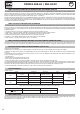
CHOICE OF REELS
Possible settings :
Type l Weight (kg) Ø l (mm) Torch Gas
steel
Ø 300 15 0.6 / 0.8 / 1.0 / 1.2 x
argon
+
CO2
Ø 200 5 0.6 / 0.8 / 1.0 x
stainless steel
Ø 200 5 0.8 x
Alu
AG5
Ø 300 7 1.0 / 1.2 x*
Pure argon
Ø 200 2 0.8 / 1.0 / 1.2 x*
*Make sure to have a teon torch liner/contact tip for alu. Remove the capillary tube.
TRIMIG 200-4S TRIMIG 250-4S.DV
Ømm
0.6 > 1 0.8 > 1.2
GAS CONNECTION
Connect the manometer (owmeter) to the gas bottle if needed, then connect the gos hose to the gas connector. To prevent gas leaks, use the hose
clips supplied in the accessories box. Make sure the gas bottle hold in place respecting chain fastening cf. FIG-IV-1
Maximum gas pressure 0.5MPA (5 bars).